Olsen Infinity User manual

1

2

3
Index
1 - Introduction .......................................................................................................................................................................5
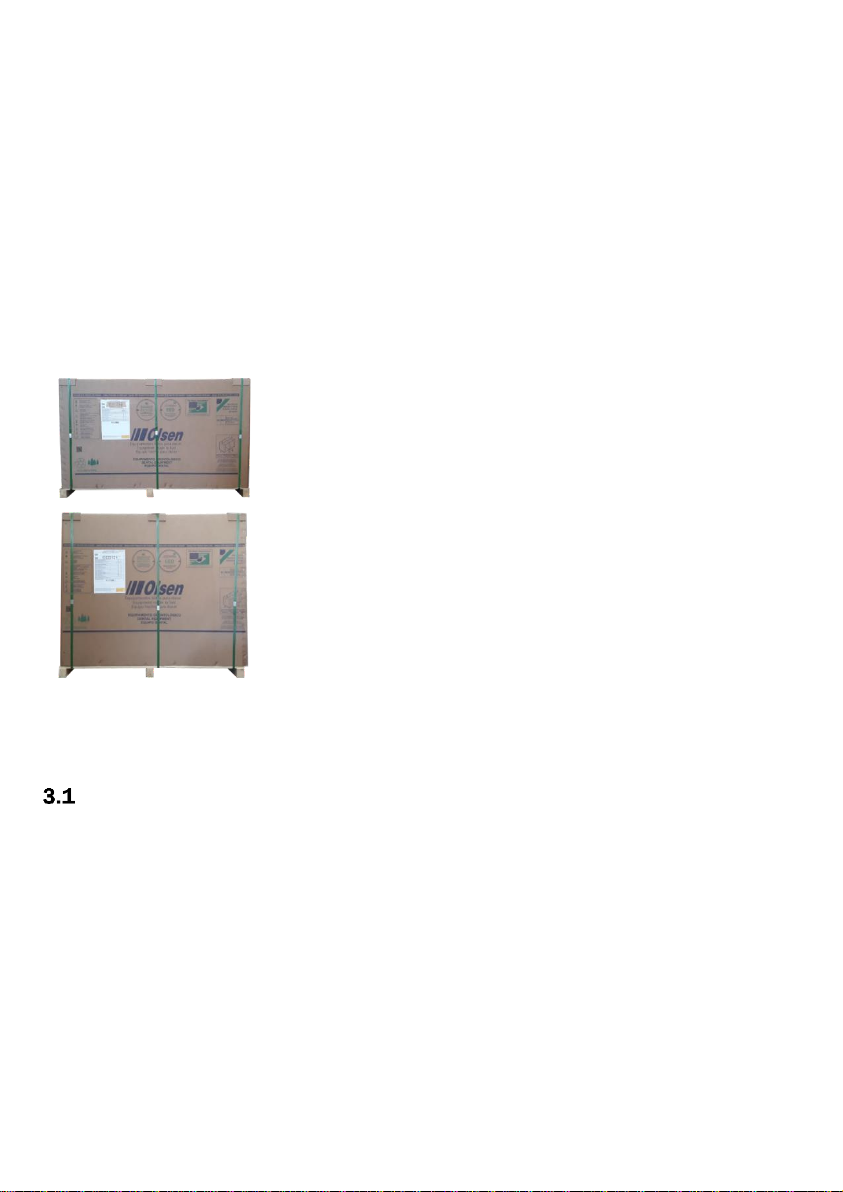
2 - Package Contents .............................................................................................................................................................5
3 - Equipment Presentation ...................................................................................................................................................5
- Standard Configuration...........................................................................................................................................5
3.1.1 - Dental Chair ..................................................................................................................................................5
3.1.2 - Assistant Module...........................................................................................................................................5
3.1.3 - Operating Light..............................................................................................................................................5
3.1.4 - Delivery System.............................................................................................................................................5
3.1.5 - Water Unit .....................................................................................................................................................6
- Optional Items.........................................................................................................................................................6
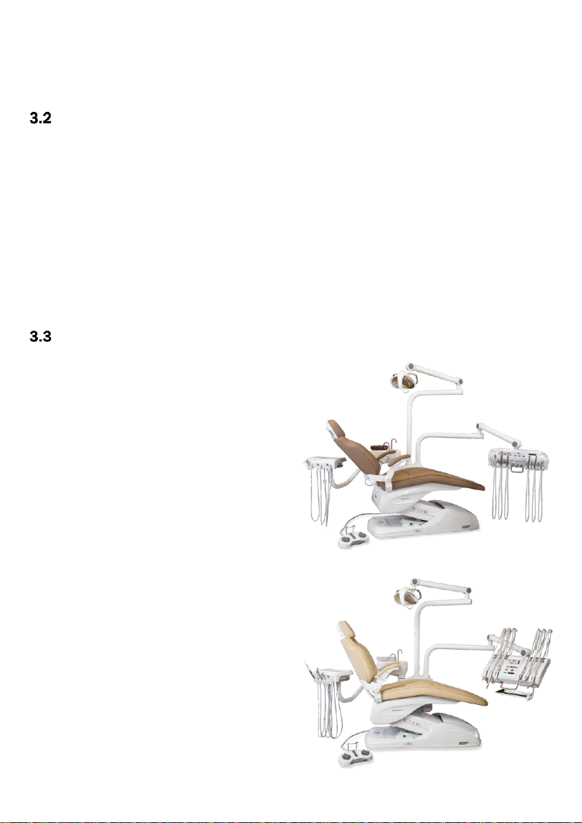
- Infinity Models.........................................................................................................................................................6
3.3.1 - Infinity Premium............................................................................................................................................6
3.3.2 - Infinity Cross Flex Premium ..........................................................................................................................6
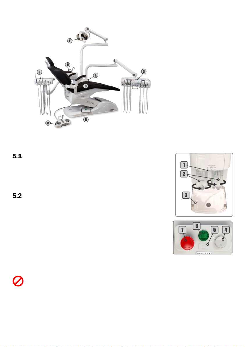
4 - Parts Identification ............................................................................................................................................................7
5 - Equipment Operating and Description .............................................................................................................................7
- Before Turning On the Equipment ..........................................................................................................................7
- Turning On the Equipment......................................................................................................................................7
5.2.1 - Delivery System.............................................................................................................................................7
5.2.2 - Electric Panel ................................................................................................................................................7
5.2.3 - Emergency Stop Switch (Optional) ...............................................................................................................8
5.2.4 - Digital Voltmeter ...........................................................................................................................................8
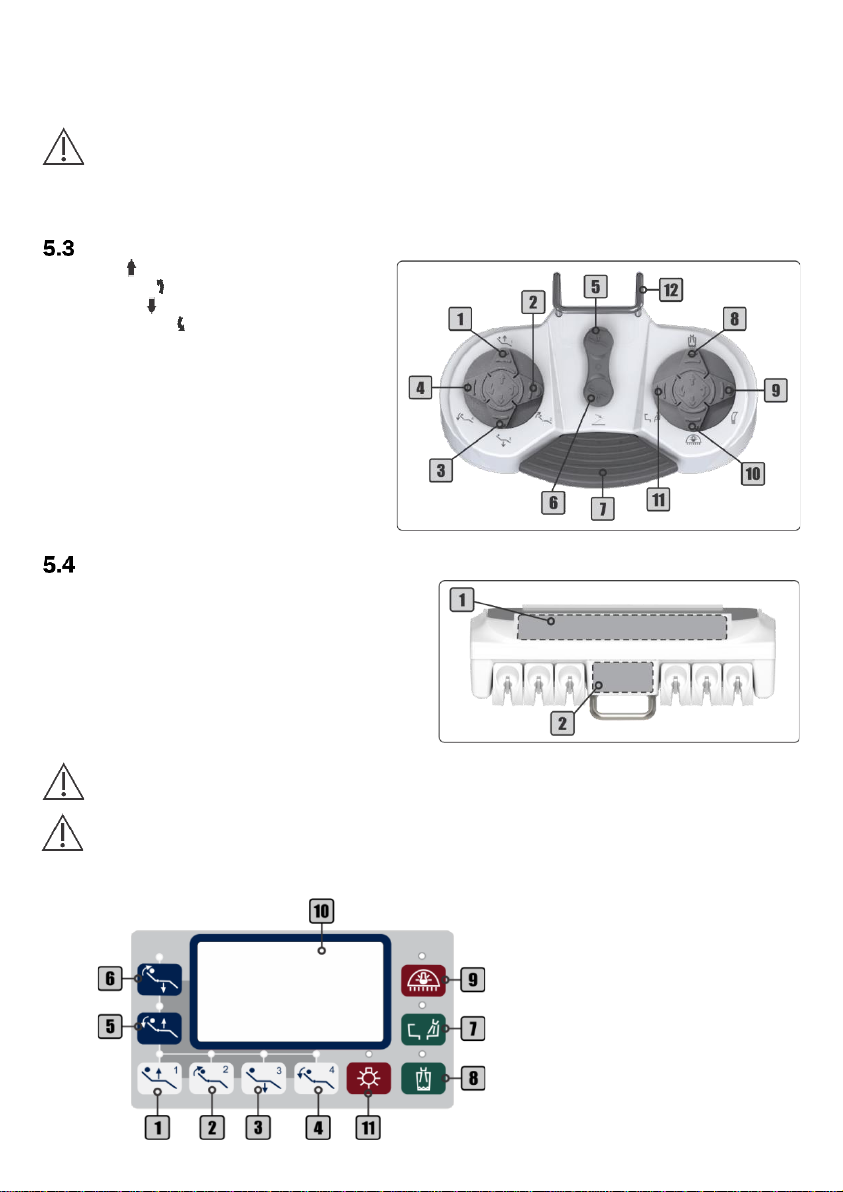
- Remote Foot Pedal Commands..............................................................................................................................8
- Working Table..........................................................................................................................................................8
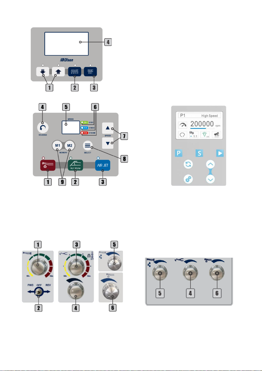
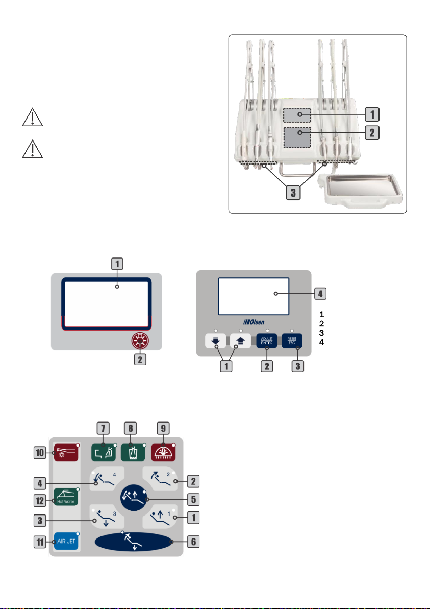
5.4.1 - Infinity Premium Working Table....................................................................................................................8
5.4.2 - Infinity Cross Flex Premium Working Table............................................................................................... 10
- Working Table Arm ............................................................................................................................................... 11
- Water Unit............................................................................................................................................................. 12
- Assistant Module.................................................................................................................................................. 12
- Operating Light..................................................................................................................................................... 12
- Dental Chair.......................................................................................................................................................... 12
5.9.1 - Zero Position .............................................................................................................................................. 13
5.9.2 - Work Position ............................................................................................................................................. 13
5.9.3 - Spit Position ............................................................................................................................................... 13
5.9.4 - Headrest..................................................................................................................................................... 13
5.9.5 - Swivel Armrest............................................................................................................................................ 14
6 - Instruments Operation ................................................................................................................................................... 14
- Pneumatic Handpiece Couplings......................................................................................................................... 14

4
- Optical Fiber Handpiece (Optional)...................................................................................................................... 14
- Scaler with LED Light (Optional) .......................................................................................................................... 14
6.3.1 - Scaler Adjustments - Operation and Basic Adjustments .......................................................................... 15
6.3.2 - Scaler Adjustments - Multifunction Display .............................................................................................. 15
6.3.3 - Scaler Tips.................................................................................................................................................. 15
- Electrical Micromotor (Optional).......................................................................................................................... 16
6.4.1 - Electrical Micromotor Basic Adjustments ................................................................................................. 16
6.4.2 - Electrical Micromotor Adjustments - Multifunction Display (Optional)..................................................... 16
6.4.3 - Brushless Electrical Micromotor - Built in (Optional) ................................................................................ 16
6.4.4 - Brushless Electrical Micromotor - Side Panel (Optional).......................................................................... 17
- Venturi Saliva Ejector........................................................................................................................................... 18
- High Power Vórtice Saliva Ejector........................................................................................................................ 18
- Vacuum Pump Adaptor (Optional) ....................................................................................................................... 18
- Way Syringe.......................................................................................................................................................... 18
- Curing Light (Optional) ......................................................................................................................................... 19
- Prophylaxis System............................................................................................................................................ 19
6.10.1 - Bicarbonate Jet........................................................................................................................................ 19
6.10.2 - Prophy-Jet (Optional)................................................................................................................................ 19
7 - Accessory Operation....................................................................................................................................................... 20
–ChronoLub Control Panel (Optional)................................................................................................................... 20
7.1.1 - ChronoLub System (Optional).................................................................................................................... 20
7.1.2 - Clock - Date and Time (Optional)............................................................................................................... 20
7.1.3 - Birthday (Optional) ..................................................................................................................................... 20
7.1.4 –Laguage ..................................................................................................................................................... 21
7.1.5 Cardiac Monitor (Optional).......................................................................................................................... 21
- Thermo Comfort (Optional) .................................................................................................................................. 21
- Air Jet (Optional) ................................................................................................................................................... 21
- X-Ray Viewer......................................................................................................................................................... 22
- Anti-Stress System (Optional) .............................................................................................................................. 22
- Monitor Holder (Optional) .................................................................................................................................... 22
- USB Charger ......................................................................................................................................................... 22
- Cart System (Optional) ......................................................................................................................................... 22
8 - Symbology....................................................................................................................................................................... 23
9 - Olsen Accredited Technical Assistance Network........................................................................................................... 24
10 - Warranty Terms............................................................................................................................................................ 25
11 - Message from the President........................................................................................................................................ 26

5
1- Introduction
Congratulations on choosing an Olsen equipment!
You have acquired high-tech equipment developed to offer the best performance in dental procedures
ensuring ergonomics and comfort, for both professional and the patient.
The purpose of this guide is to present instructions for operating the dental equipment of the Infinity line.
The images are merely illustrative and do not represent the configuration of models or the availability of items
and accessories.
The User Manual Dental Line is supplementary to this guide and should be read before operating the
equipment. It is provided in digital format (PDF) along with the order confirmation for your equipment. The user
manual presented the descriptive and technical information, installation instructions, maintenance, cleaning,
precautions of use and regulatory guidelines.
2- Package Contents
The Infinity line equipment is available in 2 packages, one for the chair and the other for the equipment.
Check the contents of each package below:
Dental Chair Box:
Standard Items:
1 Dental Chair Infinity
1 Accessories Box
Delivery Unit Box:
Standard Items:
1 Delivery Unit Infinity
1 Operation Light
1 Packing Support
1 Dental Stool
1 Infinity Quick Operation Guide
Note: items availability in the packaging may change in the case of the customer order.
3- Equipment Presentation
- Standard Configuration
3.1.1 - Dental Chair
3 Programmable Work Positions
Automatic Zero Position
Spit Position
Multi-Articulating Headrest with “Press-Click”
Adjustment System
Digital Voltmeter
Swivel Right Armrest
Integrated Junction Box
Automatic Vapor Drain
3.1.2 - Assistant Module
Additional 3-Way Syringe
Venturi Saliva Ejector
Bicarbonate Jet Prophylaxis System
Stainless Steel Tray
Blue Touch Panel
3.1.3 - Operating Light
Premium LED 8.000 to 30.000 Lux
On/Off on the Headlight (Sensor and Knob), on the
pedal and on the Command Panel
Removable Side Handles
Multifaceted Mirror
3.1.4 - Delivery System
Couplings for Low-and High-speed Handpieces
3-Way Syringe
Stainless Steel Tray
Flex Arm with Capacitive Sensor
Pedal for Chair and Handpieces Commands
Blue Touch Panel
USB Charger
X-Ray Viewer
Thermo Comfort System
Optional Items:
Separated Junction Box
Optional Items:
Handpieces
Cart System
Additional Stool
Monitor Holder

6
3.1.5 - Water Unit
Swivel at 90º
Translucent Spittoon Bowl
LED Curing Light
Bowl Flush Water Control and Cup Filler with Timer
- Optional Items
Leather Upholstery
Anti-Stress System
Emergency Stop Button
Motion Blocking Function
Anti-crushing System
Cart System
Additional Handpiece Position
Air Jet System
Optical Fiber Handpiece Coupling
Electrical Micromotor Brushless
Electrical Micromotor
Scaler with LED Light
Midwest Couplings
ChronoLub System with Multifunction Display
Cardiac Monitor
Monitor Holder
Handpiece Coupling on Assistant Module
Vacuum Pump Adaptor Set
High Power Vórtice Saliva Ejector
Quick Coupler for Saliva Ejectors and/or Vacuum
Pump
Prophy-Jet System
Additional LED Curing Light on the Assistant
Module
Junction Box
Prophylaxis in the Assistant Module
Note: optional items are defined on the customer's order.
- Infinity Models
3.3.1 - Infinity Premium
It presents the standard items of the Infinity line
(section 3.1).
3.3.2 - Infinity Cross Flex Premium
It presents, in addition to the standard items of the
Infinity line (section 3.1):
Cross Flex Working Table
Jointed Stainless Steel Tray
Coupling for Air Turbines Handpiece

7
4- Parts Identification
5- Equipment Operating and Description
- Before Turning On the Equipment
1º - Check if the equipment is properly installed in accordance with the
instructions in chapter 6 (Installation) of the User Manual Dental Line;
2º - Turn On the air compressor that supplies the equipment;
3º - Open the main water supply valve of the equipment;
4º - Turn On the equipment's power circuit breaker.
- Turning On the Equipment
1º - Turn On the On/Off switch (4);
2º - Activate the "Seat Up" command on the pedal (section 5.3) until the seat
reaches its maximum height limit;
3º - Open the protection cover (3);
4º - Close the pressure valve (1);
5º - Make sure the water tanks (2) are filled with water. If necessary, fill it with
drinkable water up to the limit indicated in each tank and reattach them
again. If you wish to place prophylactic products (low concentration);
6º - Open the pressure valve (1) and check if the water tanks (2) are well
attached and free of leaks;
7º - Close the protection cover (3);
8º - Before starting to use the equipment, check the operation of all available instruments and controls and
perform cleaning and sterilization of the instruments (chapter 7 of the User Manual Dental Line - Cleaning
and Disinfection).
Do not move the chair with the protection cover open.
5.2.1 - Delivery System
1 -Pressure Valve
2 -Water Tanks
3 -Protection Cover
5.2.2 - Electric Panel
4 -On/Off Switch
5 -Fuse Holder
6 -Digital Voltmeter
7 -Emergency Stop Button (Optional)
A -Delivery System
B -Electrical Panel
C -Remote Foot Pedal
D -Working Table
E -Assistant Module
F -Operating Light
G -Dental Chair
H -Water Unit

8
5.2.3 - Emergency Stop Switch (Optional)
The emergency stop switch interrupts the equipment power supply of and consequently interrupts any
running chair movement. To activate the emergency stop switch, simply press it. To turn it off, simply turn it
clockwise until the button unlocks, returning to the starting position.
The emergency stop switch must be deactivated for the equipment operation.
5.2.4 - Digital Voltmeter
When the On/Off switch is turned On, the voltmeter display will show the equipment mains voltage.
- Remote Foot Pedal Commands
1 -Seat Up ( )/Position 1
2 -Backrest Up ( )/Position 2
3 -Seat Down ( )/Position 3
4 -Backrest Down ( )/Spit Position
5 -Work Position
6 -Zero Position
7 -Propulsion Pedal
8 -Cup Filler
9 -On/Off Vórtice Saliva Ejector
10 -On/Off Operating Light
11 -Spittoon Bowl Flush
12 -Metal Handle
- Working Table
5.4.1 - Infinity Premium Working Table
1 -Command Panel
2 -Instruments Control Panel
The layout of the controls and panels may vary according to customer order and available
handpieces.
Some functions indicated on control panel may not be available according to the equipment
configuration.
Command Panel Models (1):
1 -Seat Up/Position 1
2 -Backrest Up/Position 2
3 -Seat Down/Position 3
4 -Backrest Down/Spit Position
5 -Work Position
6 -Zero Position
7 -Spittoon Bowl Flush
8 -Cup Filler
9 - On/Off Operating Light
10 -X-Ray Viewer
11 -On/Off X-Ray Viewer

9
Instruments Control Panel (2):
The switches and knobs presented below can be presented on the instrument panel according to the
instruments available at the dental table.
1 - Adjustments
2 -Adjust/Enter
3 -Reset/Esc
4 -Multifunctional Display
ChronoLub System and Multifunctional Display
Version with ChronoLub System
System
1 - Electrical Micromotor Speed Control
2 - Electrical Micromotor Direction Control
3 - Scaler Power Control and General Function Selector - Perio/Endo
4 - Scaler Water Control
5 -Brushless Micromotor Water Control
6 - Optical Fiber Water Control
Description of controls in section 6.4.4
Brushless - Side Panel (Optional)
1 - On/Off Optical Fiber Light
2 - On/Off Thermo Comfort
3 - On/Off Air Jet
4 - Reverse
5 - Display
Brushless Electrical Micromotor (Optional)
6 - Transmission Indicators
7 - Adjustments
8 - Select
9 - Memory

10
5.4.2 - Infinity Cross Flex Premium Working Table
1 -Top Panel Cross
2 -Command Panel
3 -Instruments Control Panel
The layout of the controls and panels may vary
according to customer order and available
handpieces.
Some functions indicated on control panel may
not be available according to the equipment
configuration.
Top Panel Cross Flex (1) Models:
Command Panel (2):
X-Ray Viewer
1 -X-Ray Viewer
2 -On/Off X-Ray Viewer
1 -Adjustments
2 -Adjust/Enter
3 -Reset/Esc
4 -Multifunctional Display
ChronoLub System (Optional)
1 - Seat Up/Position 1
2 - Backrest Up/Position 2
3 - Seat Down/Position 3
4 - Backrest Down/Spit Position
5 - Work Position
6 - Zero Position
7 - Spittoon Bowl Flush
8 - Cup Filler
9 - On/Off Operating Light
10 - On/Off Optical Fiber Light
11 - On/Off Air Jet
12 - On/Off Thermo Comfort

11
Instruments Control Panel (3):
Note: these controls are provided below the instrument to which they refer.
- Working Table Arm
Flex Arm (5 and 6): features 2 articulations and pneumatic
lock that are disabled by touching the capacitive handle (2), allowing
the working table movement.
Do not move the table upright without disabling the
pneumatic brake. This may damage the flex arm locking
system.
1 - Speed Adjustment for Electrical Micromotor
2 - Electrical Micromotor’s Rotation Direction Control
3 - Scaler Intensity Control and Function Selector - Endo/General-
Perio
4 - Scaler Water Control
5 - Optical Fiber Water Control
Brushless Electrical Micromotor (Optional)
1 - Reverse
2 -Display
3 -Transmission Indicators
4 -Adjustment Keys
5 -Memory
6 -Selection
Description of controls in section 6.3.3
Brushless - Side Panel (Optional)

12
- Water Unit
For water commands: use water commands on remote foot pedal
(section 5.3) or command panels on working table (sections 5.4) and
assistant module (sections 5.7).
The water spouts for spittoon bowl (1) and cup filler (2) are
removable.
- Assistant Module
1 –Assistant Module Electrical Panel;
2 –Sodium Bicarbonate Reservoir;
3 –Stainless-Steel Tray.
Note: the layout of the assistant module may vary according to customer order and available handpieces.
- Operating Light
To activate the operating light: press the On/Off
operating light command (1) on the command panel
(section 5.4 and 5.7) or remote foot pedal (section 5.3) to enable sensor
(3) and control knob (2).
To turn On/Off the operating light: pass the hand in front of the
sensor (3) approximately 5 cm away or press the control knob (2).
To change the light intensity: hold your hand in front of the
sensor (3) or turn the control knob (2) until the operating light shows the
desired intensity.
- Dental Chair
To move backrest and seat use the keys on the command panel (sections 5.4 and 5.7) and in the buttons
located on remote foot pedal (section 5.3).
1.1 - Seat Up/Position 1
1.2 - Backrest Up/Position 2
1.3 - Seat Down/Position 3
1.4 - Backrest Down/Spit Position
1.5 - Working Position
1.6 - Zero Position
1.7 - Spittoon Bowl Flush
1.8 - Cup Filler
1.9 - On/Off Operating Light
Assistant Module Commands (1):

13
5.9.1 - Zero Position
Press the Zero Position key to automatically adjust the seat to the lowest position and
backrest in the highest position simultaneously, to facilitate patient entry and exit.
5.9.2 - Work Position
To save a work position:
1º - Press the Zero Position key (section 5.8.1);
2º - Adjust the backrest to the desired position;
3º - Adjust the seat to the desired position;
4º - Press the Work Position key for 5 seconds. The equipment will emit 2 long beeps;
5º - Press command 1 (Seat Up) while the equipment beeps; The equipment will emit 2 short beeps to confirm
the procedure;
Note: the time to record the working position is only 2 seconds between steps 4 and 5, then when you hear the
first long beep (step 4), quickly press one of the available commands (1 to 3) to record the working position. If
none of the 3 commands is pressed in these 2 seconds, the equipment will emit 3 short beeps, canceling the
operation.
6º - Press the Zero Position key.
Repeat the previous steps by replacing the command 1 by the command 2 (Backrest Up) to record the
working position 2 or by the command 3 (Seat Down) to save the working position 3.
To perform a working position:
1º - Press the Work Position key; The equipment will emit a short beep;
2º - Press the command for the desired saved working position (1 to 3); The equipment beeps twice confirming
the operation.
The dental chair moves the backrest and seat simultaneously to the previously saved position and lights
the operating light at the last intensity used.
Note: after pressing the Work Position key, the time for position selection is 4 seconds. If no key is pressed within
this time, the equipment cancels the operation.
5.9.3 - Spit Position
To perform the spit position:
1º - Press the Work Position key (section 5.8.2);
2º - Press the command 4 (Backrest Down).
The equipment emits 2 beeps, turn Off the operating light, the backrest goes up and activates the water in
the bowl. After 8 seconds, the equipment returns to the position before the command.
Note: the spit position is pre-recorded at the factory and cannot be changed.
5.9.4 - Headrest
To adjust the headrest (2) position: press the button (1) to move the headrest
(2) to the desired position, then release the button.
To adjust the height of the headrest: move the bar (3) until you reach the
position. The headrest bar (3) allows adjustment with up to 10 cm from the
backrest.
Backrest Up ( )
Seat Up ( )
Backrest Down ( )
Seat Down ( )

14
5.9.5 - Swivel Armrest
To move the swivel armrest: press the trigger (1) and push the armrest down.
6- Instruments Operation
- Pneumatic Handpiece Couplings
Before starting the operation connect the handpiece (1) to
the coupling by attaching it to the coupling ring (2), ensuring that it
is properly connected and that there is no leakage of air or water.
To activate the rotation: press the propulsion/activation
pedal (5). The higher the pressure applied to the pedal, the more
speed in the handpiece, until reaching the pressure limits of the
equipment.
To adjust the spray: turn the adjusting ring (4) until the
desired volume of water. To adjust the maximum flow of water. To adjust the maximum flow of
water, bring the spray adjustment indicators (3) closer to each other. To decrease the flow of
water, rotate the ring so it distances one indicator from the other. The completely opposite
points indicate the minimum water regulation for the spray.
- Optical Fiber Handpiece (Optional)
Before starting the operation connect the optical fiber
handpiece to the coupling by attaching it to the coupling ring (1),
ensuring that it is properly connected and there is no leakage of
air or water.
To activate the rotation: press the propulsion/activation
pedal (2). The higher the pressure applied to the pedal, the more
speed in the handpiece, until reaching the pressure limits of the
equipment.
To turn the coupling’s light On/Off: use the On/Off optical
fiber light (3) on the command panel (section 5.4 and 5,7) of the
working table.
To adjust the spray: use the optical fiber water control knob
(4) on the instrument control panel.
- Scaler with LED Light (Optional)
Before starting the scaler operation, install the tip on
the transducer (1) and connect the transducer (1) to the
coupling (3) checking if are connected.
To attach the transducer to the coupling: align the
adjustment indicators (2) of the two parts and carefully
insert them.
To install the scaler tips: insert the tip into the
transducer (1) by threading it carefully, then insert the
Torque wrench (4) into the tip and then rotate it clockwise
until it is tight. To remove the tip, turn it counterclockwise
with the Torque wrench (4).
To install a file adapter (not supplied with scaler): attach the adapter to the transducer (1) and screw it

15
gently. Insert the file into the tip of the adapter, thread the tip and then use the Endo wrench (5) to tighten. To
remove the adapter, use the Endo wrench (5) to loosen it and then carefully unscrew.
6.3.1 - Scaler Adjustments - Operation and Basic Adjustments
To activate the scaler: push the propulsion/activation
pedal (6).
To adjust the vibration power: turn the control knob
(7) until the desired power is reached.
To toggle functions: push the control knob (7) in direction of
the table for "GP" function (General and Perio). Pull the knob gently in the
opposite direction of the table for "E" (Endo) function.
To adjust the water (including for multifunction display): use the control knob (8) on the instrument control
panel (section 5.4).
6.3.2 - Scaler Adjustments - Multifunction Display
When removing the scaler from the holder or extending the
rod (Cross Flex), the multifunctional display (9) screen will identify
the scaler, the number of its position on the working table
(1 to 5), the selected function ("PG" or "E") and will display the
vibration power bar.
To adjust the vibration power: use the keys to increase
(11) or decrease (10) the power, which will be indicated on the
display.
To toggle functions: use the key (12) to toggle between "PG"
(General and Perio) and "E" (Endo) functions indicated in the center
of the multifunctional display.
It is not possible to switch the PG/E functions during the operation of the scaler (while
propulsion/activation pedal is activated).
6.3.3 - Scaler Tips
The tips GD1, PD1 and PD3 accompany the scaler. The power and application information for each tip is
available in the table below.
Note:
1 -Do not use the tip on features other than those specified by the manufacturer.
2 -Do not exceed the power limit for each tip. That could damage the tip and the scaler.

16
- Electrical Micromotor (Optional)
Before starting the operation connect the handpiece to the
electrical micromotor (2).
To activate the rotation: push the propulsion/activation
pedal (1).
6.4.1 - Electrical Micromotor Basic Adjustments
To adjust the speed: turn the control knob (3) until the
desired speed is reached.
To change the direction of rotation: use the rotation direction
control (4).
- FWD: clockwise; - OFF: Off; - REV: counterclockwise.
6.4.2 - Electrical Micromotor Adjustments - Multifunction Display (Optional)
When removing the electrical micromotor from the holder or
extending the rod (Cross Flex), the multifunction display (5) will
identify the electrical micromotor, the number of its position on the
working table (1 to 5), the direction of rotation and will show the
speed bar.
To adjust speed: use keys to increase (7) or decrease (6)
speed.
To change the direction of rotation: use the Adjust/Enter key
(8) to toggle the direction of rotation.
(FWD) Clockwise (REV) Counterclockwise
6.4.3 - Brushless Electrical Micromotor - Built in (Optional)
Before starting the operation, connect the handpiece to the electrical micromotor (8).
To activate the rotation: press the propulsion/activation pedal (7).
To select the transmission: use the Select key (5). The selection is indicated by LED’s (3): 20: 1; 1: 1 and
1: 5.
To reverse the rotation: use the Reverse key (1).
To adjust speed: use the adjustment key (4). The speed relation of each transmission with the value of the
display (2) is indicated in the above table.
Example:
Display value: 15

17
Selected gear ratio: 1:1 Factor: x1.000
Rotation speed: 15 x 1000 = 15,000 rpm
To activate memory: press the desired Memory key (6). The display will show the speed and the LED (3) will
indicate the present transmission.
To record memory: select the transmission and adjust the speed of rotation to store. Press and hold one of
the Memory key (7) until the system emits 2 beeps, indicating that the memory has been recorded.
To save the second available memory repeat the same procedure.
To adjust the electrical micromotor water: use the water control knob (9) on the instruments control panel.
6.4.4 - Brushless Electrical Micromotor - Side Panel (Optional)
Before starting the operation, connect the
handpiece to the electrical micromotor (16).
To activate the rotation: press the
propulsion/activation pedal (14) or the Manual
Start key (11). The On/Off indicator (2) will turn
blue.
To select a preset program: use the Program
key (8). There is 7 programs available, according
the table below:
The selected direction is shown on the display (1).
To record program: select program P1 or P2, then select the
desired gear ration and adjust the speed. Press and hold the Program key
(8) until the system save your settings.
To adjust speed: use the adjustment keys (13) to increase or decrease speed. Please see the table below
for speed range for each gear ration value:
The selected direction is shown on the display (5).
To select the gear ratio: use Gear Ratio key (10). There are the following
values available: 1:5, 1:1, 4:1, 10:1, 16:1 and 20:1.
The selected direction is shown on the display (4).
To change the rotation direction: use the Direction key (9).
The selected direction is shown on the display (3).
To adjust the micromotor water: use the water control knob (15) on
the instruments control panel (section 5.4).
To access setup menu: press and hold the Setting key (12). Use the
Setting key (12) to select the desired option.
To adjust LED options: use the adjustment keys (13) to set the
parameter.
To adjust pneumatic activation method: use the adjustment keys (13) to set the parameter. The selected
pneumatic activation method is shown on the display (6).
LED Off
LED On
without delay
LED On
with 10s delay
When pedal (14) is pressed micromotor
performs the maximum speed adjusted
Micromotor performs speed according to
the pressure on the pedal (14)
Forward
Reverse

18
To adjust input pneumatic pressure: use the adjustment keys (13) to set the parameter.
Note: the micromotor system preset by the factory according to the internal equipment pressure. It is not
recommended to change the pressure parameters.
- Venturi Saliva Ejector
Before starting the operation, fit the cannula to the 6.3 or 9,35 mm adapter
(3).
To activate the suction: remove the ejector (2) from the holder (1).
To deactivate the suction: place the ejector in its holder (1).
The cannula adapter (3) is removable for cleaning.
- High Power Vórtice Saliva Ejector
Before starting the operation, fit the cannula to the 6,3, 9,5 or
11 mm adapter (3).
To enable/disable suction for Vórtice ejector (2): use the On/Off
Vórtice saliva ejector button (1) on the pedal.
The cannula adapter (3) is removable for cleaning.
- Vacuum Pump Adaptor (Optional)
Before starting the operation, fit the cannula to the 6,3, 9,5 or
11 mm adapter (5).
To activate suction: remove the vacuum pump suction (2) from its
holder (1). The vacuum pump will work automatically.
To adjust suction flow: to decrease the suction flow, turn adaptor's
body (3) away from the indicators (4). The more distant, the smaller the
suction flow. For the maximum suction flow, align the indicators (4).
To deactivate the suction: place the vacuum pump in its holder (1).
The cannula adapter (5) is removable for cleaning.
- Way Syringe
Before beginning the use of the 3-way syringe (5), connect the syringe
tip (3) by pressing the locking ring (4) into the correct fit.
To emit air jet: press the air button (1).
To emit water jet: press the water button (2).
To emit spray jet: press simultaneously the air (1) and water (2)
buttons.
Set minimum activation pressure
from 0.03 to 0.10 MPa
Set maximum input pressure
from 0.20 to 0.40 MPa

19
- Curing Light (Optional)
Before starting the curing light use, install
the tip (1) and the light hood (2).
To install the tip: first, attach the light hood
(2) to the tip (1) and then attach it to the curing
light unit (3). The tip (1) must be pushed all the way to the fitting end.
To activate/deactivate the curing light: press the On/Off button (5) twice.
The green LED (4) indicates that the curing light is operating. The curing light unit
will run for 20 seconds and will turn Off automatically.
To toggle the operating mode: each tap on the selection button (9) switches
the operation mode. Press the selection button (9) until the orange LED indicates
the desired mode.
The curing light operates in the following modes:
−Continuous (6): turns on the maximum power for 20 seconds;
−Ramp (7): turns on the minimum power, gradually increasing. In 5
seconds reaches its maximum power until the cycle of 20 seconds is
finished;
−Pulse (8): the device blinking for 20 seconds.
- Prophylaxis System
6.10.1 - Bicarbonate Jet
Before starting use of the bicarbonate jet,
its necessary deposit bicarbonate sodium in the
reservoir (4), check for moisture in the filter (8) and connect
the bicarbonate jet handpiece (3) to its coupling (2).
To fill the bicarbonate reservoir: open the reservoir (4) by
turning the cover (6) anticlockwise and deposit the bicarbonate
sodium until to the red line (5). Close the reservoir.
To remove condensed water in the filter: press the valve
(7) on the base of the filter (8) to drain the water.
To activate/deactivate the bicarbonate jet: press the
progressive/activation pedal (1). The more pressure on the pedal,
the greater the volume of the jet emitted by the handpiece, until
reaching the pressure limits of the equipment.
To adjust the spray: see section 6.1.
Clean the sodium bicarbonate tank (4) at the end of each procedure.
6.10.2 - Prophy-Jet (Optional)
Before starting Prophy-Jet (3), deposit up to 15g of
sodium bicarbonate for dental use in the sodium bicarbonate
tank (4) and attach the Prophy-Jet to the pneumatic coupling
(2) available on the assistant module (section 5.7) or
pneumatic coupling for low-speed rotation in the working table
(section 5.4).
To activate/deactivate: push the propulsion/activation pedal (1). The higher the pressure applied to the
pedal, the greater the volume of the jet emitted by the handpiece, until reaching the pressure limits of the
equipment.
Clean the sodium bicarbonate tank (4) at the end of each procedure.

20
7- Accessory Operation
–ChronoLub Control Panel (Optional)
1 -Decreases
2 -Increases
3 -Adjust/Enter
4 -Reset/Esc
7.1.1 - ChronoLub System (Optional)
When removing the handpiece from the holder or extending the rod (Cross
Flex), the multifunction display will identify whether the coupling is for low or high
rotation, show the number of its position on the working table (1 to 5),
and a segmented circle that represents the time of use of the handpiece. When
the last segment starts blinking, the handpiece can be used for another 2 minutes.
When you run out of time, the screen will show a spray can and will emit 3
beeps. From this moment whenever the handpiece is removed from the holder, the
system will beep, repeating the warning every 2 minutes while the handpiece is in
use or out of the holder.
After lubricating the handpiece, with it out of the holder or extending the rod
(Cross Flex), press the Reset/Esc key (4) for 3 seconds to restart the timing. This
procedure can be done at any time.
7.1.2 - Clock - Date and Time (Optional)
To access the Clock function: press the Adjust/Enter key (3) for 3
seconds to access the "AJUSTE" screen. Use the adjustment keys (1and 2) to
select the “1. RELÓGIO” option.
To adjust the clock: press the Adjust/Enter key (3) to access the "AJUSTAR
RELÓGIO" screen. Use the adjustment keys (1and 2) to change the selected
value.
To toggle the selection between hour, minute, day, month and year: use
the Adjust/Enter key (3).
To save the changes: press the Adjust/Enter key (3) for 3 seconds.
To cancel and return to the previous screen: press the Reset/Esc key (4).
The options in the "AJUSTE" screen may change if the cardiac monitor
(optional) is available on the device. (section 6.11.4).
7.1.3 - Birthday (Optional)
To access the Anniversary function: press the Adjust/Enter key (3) for 3
seconds to access the "AJUSTE" screen. Use the adjustment keys (1and 2) to
select the “2. ANIVERSÁRIO” option.
To change the anniversary date: press the Adjust/Enter key (3) to access
the "AJUSTE ANIVERSÁRIO" screen. Use the adjustment keys (1and 2) to change
the selected value.
To change the selection between day, month and year: use the
Adjust/Enter key (3).
To save the changes: press the Adjust/Enter key (3) for 3 seconds.
To cancel and return to the previous screen: press the Reset/Esc key (4).
The options in the "AJUSTE" screen may change if the cardiac monitor
(optional) is available on the device. (section 6.11.4).
Table of contents
Languages:
Other Olsen Dental Equipment manuals
Popular Dental Equipment manuals by other brands

Durr Dental
Durr Dental VistaVox S operating instructions

Castellini
Castellini SKEMA 6 Series operating instructions

Durr Dental
Durr Dental Hygosonic Installation and operating instructions

Carestream DENTAL
Carestream DENTAL CS 3600 User and installation guide

KaVo
KaVo MASTERmatic LUX M07 L Instructions for use

orangedental
orangedental spot-on nxt Instructions for use