olympia electronics BS-634 User manual

BS-634, BS-636
4 and 6 zone Fire Detection Panels
921636000_09_023
Thank you for purchasing this product of Olympia Electronics. A European manufacturer.
GENERAL
The family of fire detection panels consist of 2 types( 4 and 6 zone) with identical operation and indications. The panels have
2 independent siren outputs, Alarm relay, Programmable output for telephone operators and a relay per zone . The required
battery for the panels is the type Α-986 (12V/7Ah). All functions and indications are according to European Norms ΕΝ 54-2
and EN 54-4.
Top cover
retaining screws
Control Keyboard and
indication leds
Mounting holes
Battery compartment
Α-986
MODE selection
microswitch
Relay per zone
connection terminals
Zone connection terminal
General output connection (Sirens,
relay alarm,24V)
P
+A
_A
Operation adjustment
of zone relay
Mains voltage connection
terminal block (220-240V AC)
Figure 1. Schematic diagram of the panel
Mounting hole
Extra earth
terminals
Page 1 from 9
High Quality European based Manufacturers

Indication LED description
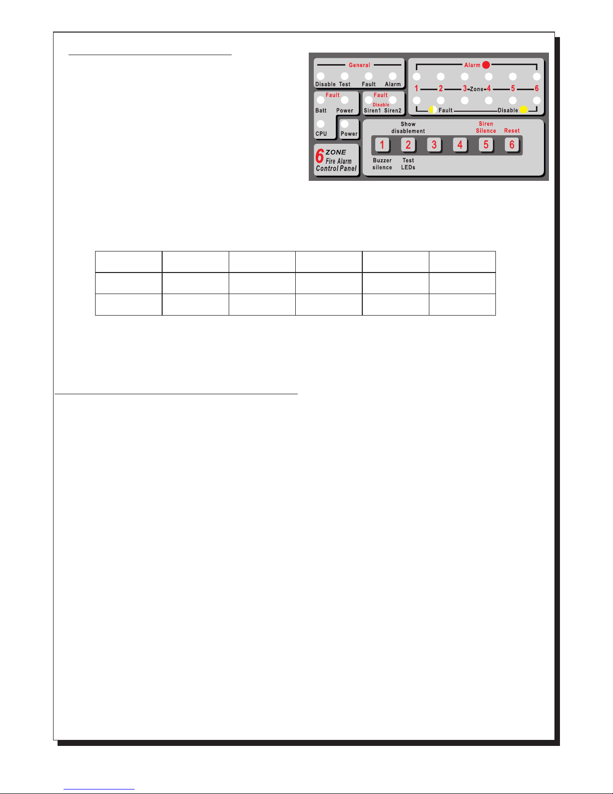
The schematic shows the control keyboard and the
indication plate of a 6 zone BS-636 panel. Starting from the
top left side we can see 4 indicators marked 'General'.
The 'Disable' LED lights in every DISABLE condition.
The 'Test' LED lights in every TEST condition .The panel
does not has test condition as specified in 11 of EN 54-2.
The 'Fault' LED lights in every FAULT condition. Blinks
when we have a FAULT and the buzzer is silenced.
The 'Alarm' LED lights when we have an ALARM condition.
Blinks when we have an ALARM and the buzzer is silenced.
The next group of indicators is the 'Alarm' indication LEDs.
These indicators light when a corresponding zone issues an ALARM condition. Below this group we have the
'Fault/Disable' indication for each zone. When the panel monitors an open or short circuit conditions in a zone then the
corresponding LED will blink. If a zone is disabled the corresponding LED will light.
Below the `General` indicator group we can find the indication group called `Fault`. The 'Batt' LED and 'Power' LED in
combination, show us faults concerning the power supply. These combination are shown in the panel below.
Batt Fault
Power Fault
Lack of
AC voltage
Battery
Overcharging
Battery
Discharged
Battery
Absent
Charger
Error
Lights
----
Lights
Lights
Lights
Blinks
Blinks
Lights
Blinks
Blinks
The 'CPU' LED lights to indicate a problem with the main processor unit (System fault).
The green 'Power' LED lights to indicate valid internal voltages and blinks when the mains AC power supply fails.
.
The LEDs marked 'Siren1' and 'Siren2' correspond to the siren outputs. If a siren out has a short circuit or open circuit then
the corresponding LED will blink. If a siren is disabled the corresponding LED will light.
Control keyboard description/operation
The panel is controlled/ operated using the six numeric keys (1 to 6) found on the front panel. When a key is pressed a short
tone is issued.
The panel has three access levels.
Access level 1:
has all the functions that can be done directly from the user without using a code. These operations are:
Buzzer silence / Buzzer reactivation . If an alarm of fault condition is issued then the internal buzzer will sound. Pressing
the "1" key will silence the buzzer. ( The buzzer sounds periodically once every minute.) Pressing this key again will reactive
the buzzer.
Viewing disabled sirens-zones/Lamp test. Pressing the "2" key will have the following affect. If any sirens are disabled
then the panel will issue 3 short tones, by lighting the ‘General Disable’ LED, and the disabled sirens will be shown by
lighting the corresponding LEDs Siren1 and Siren2 of the disabled sirens. Then the LEDs will stop lighting and the panel
will issue again 3 short tone, by lighting the ‘Zone Disable’ LED, and the disable zones will be shown by lighting the
corresponding LEDs of the disabled zones. After a while these indicators are switched off and a lamp test is conducted by
lighting the LEDs. The panel then returns to normal operation. The above tests can be conducted only if the panel is in
quiescent state (No fault or alarm conditions).
Access level 2:
Includes all the functions that the user can do and an access code is required. The code is "34”, it is the same for all panels
and cannot be changed. The functions that can be implemented using this code are the following:
Siren Silence. When an alarm is issued and we want to silence the sirens then we must enter the user code
( 34 ) and then the keys number '5' and '5'. The sirens are silenced but the internal buzzer continues to sound. The panel
remains in normal operation. A new alarm from another zone will resound the sirens.
Panel Reset. When an alarm or fault condition has occurred and we want to reset the panel we must enter the user code
(34) and then the keys number '5' and '6’. The panel lights all LEDs in sequence and then enters normal operation.
Zone enable/disable. If we want to disable the operation of specific zones then we must enter the user code
( 34 ) and then the keys number '5' and '4'. The LED marked 'General disable' start to blink, and if a zone is disabled the
Page 2 from 9 921636000_09_023

Access level 3:
These functions are implemented during the installation and need the technical code to be accessed. The technical code is
"364", it is the same for all panels and cannot be changed. These functions that can be implemented using the technical
code are activation methods used for the relays and can be done only if the panel has not issued an alarm or fault condition.
These functions are ancillary and not required by the EN 54-2.These methods of programming are:
AUX RELAY programming. If we want to program the operation behaviour of the AUX RELAY we must enter the technical
code ( 364 ) and then press the number key '5'. The 'General fault' and 'General alarm' LEDs start to blink . The Alarm LED
of zone 1 and zone 2 show the way the AUX RELAY is programmed according to the table below.
corresponding 'Alarm' LED lights to indicate this. Using the keys 1, 2, 3, 4, 5 and 6 we can enable or disable the
respective zones. The disabled zones light the corresponding LED. The panel exits this mode if no key is pressed for
more than 30 seconds. The panel then conducts an automatic RESET and enters normal operation mode. All disabled
zones are supplied with the proper voltage but cannot issue an alarm or fault condition. If we have disabled zones then
this is indicated with the indicators 'General disable' and the corresponding Disable LED zone and the buzzer sounds
once every minute.
Siren enable/disable: If we want to disable the operation of specific sirens the we must enter the code (34) and then the
keys numbers '6' and ‘6’. The LED marked 'General Test' start to blink, and if a siren is disabled Siren1 LED lights for
siren 1 and Siren2 LED lights for the siren 2. Using the keys 1 and 2 we can enable or disable the respective sirens. The
disabled sirens have a LED lighted. The panel exits this mode if no key is pressed for more than 30 seconds. The panel
then conducts an automatic RESET and enters normal operation mode. All disabled sirens are supplied with the proper
voltage but the panel cannot enable them or read their condition. If we have disabled sirens then this is indicated with the
indicator 'General disable' and the buzzer sounds once every minute.
The default setting of this relay is set to be activated from a general alarm and immediately with no delay. In this
programming mode if the keys '1' and '2' are pressed , we can toggle the LEDs ON or OFF until we archive the desired
behaviour according to the table above. In order to exit this programming mode and to store the settings in memory press
the key '6' or do not press any key for more than 30 seconds. This system will conduct an automatic RESET and will enter
normal operation mode.
ZONE RELAY programming. If we want to program the operation behaviour of the zone relays then we must enter the
technical code ( 364 ) and then press the number key '5'. The 'General fault' and 'General alarm' LEDs start to blink. The
Fault/Disable LED of zone 1 and zone 2 show the programmed activation method of the zone relays according to the table
below.
The default operation method for the zone relay is set to permanent activation. Using the keys '3' and '4' we can
toggle the ON or OFF state of the LEDs until the desired activation programming has been reached. In order to exit this
programming mode and to store the settings in memory press the key '6' or do not press any key for more than 30 seconds.
This system will conduct an automatic RESET and will enter normal operation mode.
We can also program the RELAY so that it can cooperate with BS-680 or BS-684 type electrovalves by shorting
the adjustment jumper. In this case the RELAYS are activated for 10sec. during the alarm. After 10sec. they are
deactivated.
RESOUND sirens. It is possible to configure to automatically re-sound the sirens following an alarm in another zone. You
must enter the technical code (364) and then press the number key '5'. The 'General fault' and 'General alarm' LEDs start to
blink. If the Alarm zone 4 led is off the sirens resound following an alarm in another zone else if the led is on the sirens does
not resound. By pressing the key '5' you can change the configuration.
LED Alarm zone 2
Fault zone 2
LED Alarm zone 1
Fault zone 1
General Alarm
Direct activation
Permanent
activation
General Alarm
Delay 45 sec
Activated for
10 sec
General Alarm
Delay 2 min
Activated for
30 sec
General Fault
Direct activation
Activated for
60 sec
LED Off
LED Off
LED Off
LED Off
LED On
LED On
LED Off
LED Off
LED Off
LED Off
LED On
LED On
LED On
LED On
LED On
LED On
Page 3 from 9 921636000_09_023

Connections
The two panels in the family have the same connections. The main differences in these panels is the number of zone
available and the number of zone relays. The common outputs, the maximum consumption and the operation
procedures are identical for all the panels.
Connecting detectors and break-glass call points to zones.
By default each zone terminal block has a pre-installed terminal resistor (5Κ6). This resistor must be removed and
installed on the last device of the zone or is left connected on the zone terminals if the zone is not used. The connections
to all the zone are identical. What is shown in figures 2, 3 and 4 for zone 1 is valid for all the zones.
The total number of connected devices per zone is 30.
All cable zones must be insulated, to earth ground, to meet EMC requirements.
The cable length for each zone must not exceed the 1.5 kilometres with a cross section cable of 1.5mm².
Page 4 from 9
Figure 2. Connecting 4 detector bases to zone 1. Each base can accept BS-655, BS-660 or BS-667
detectors. A remote indication LED BS-572 is connected to one of the detectors.
Figure 3. Connecting 2 call points BS-536 and 2 detector bases to the same zone.
Figure 4. Connecting
these detectors must also be connected to the terminals 24V_M in order to be supplied with power.
3 Gas detectors BS-685 or BS-686. Besides the connections to the zone terminals
Ζ1 Ζ2 Ζ3Ζ1 Ζ2 Ζ3
5Κ6
BS-572
remote
LED
R
Terminal
resistor
Ζ1 Ζ2 Ζ3
Break-glass
call point
BS-536
OUT IN
Break-glass
call point
BS-536
OUT IN
Detector
base
Detector
base
Detector
base
Detector
base
5Κ6
Terminal
resistor
Ζ1
F_OUT
24V_M Ζ2
5Κ6
Terminal
resistor
ZON E
10- 3 0V NCNO C
Gas
Detector
BS-685
ZON E
10- 3 0V NCNO C
BS-685
Gas
Detector
ZON E
10- 3 0V NCNO C
BS-685
Gas
Detector
-R
O
U
T
-
-
L
N
I
T
+
U
R
O
N
+
L
I
-R
O
U
T
-
-
L
N
I
T
+
U
R
O
N
+
L
I
-R
O
U
T
-
-
L
N
I
T
+
U
R
O
N
+
L
I
-R
O
U
T
-
-
L
N
I
T
+
U
R
O
N
+
L
I
-R
O
U
T
-
-
L
N
I
T
+
U
R
O
N
+
L
I
-R
O
U
T
-
-
L
N
I
T
+
U
R
O
N
+
L
I
Detector
base
Detector
base
921636000_09_023

Besides the terminals that were described up to now the panel also has the following outputs :
24V_M: A 24Vdc output that is interrupted in the event of a panel reset. It is mainly used for powering gas
detectors or other devices that need an interrupted power supply when the panel is resetting. If this output
is short-circuited then the LED marked 'General fault' is lighted.
24V_P: A 24Vdc power output that is not interrupted in the event of a reset. It can be used to power
electromagnetic door latches.
Relay AUX : Voltage free relay contacts that by default are programmed to operate when the panel issues
an alarm condition.
Zone Relays : Voltage free relay contacts that are activated in the event of an ALARM on the
corresponding zone. All panels offer a relay per zone. We can use these contacts to activate devices or
operations that must be done when a specific zone issues an alarm ( i.e. Activating electromagnetic door
latches, activating electro-valves ). Figure 6 shows such an installation.
ATTENTION: Zones and aux relays are rated at 30VDC and 5A maximum. No 230VAC signals can be
connected to this relays.
F_OUT (Fault Output) : This output is by default programmed to operate in every fault condition issued
by the panel.
If it is required that this output be activated by an alarm condition then we must set the MODE switch 2 to
the ON position (To meet the requirements paragraph 8.8 of EN 54-2 the MODE switch 2 must be placed
to OFF position). This output is an open-collector output suitable for controlling the BS-489 telephone
operator.
OUTPUT +A,-A. This output is used only for production proposes. This must not be used by any other
technician only technician from olympia electronics.
Siren - Sounder Connections
Each panel offers 2 independent circuits for connecting sirens, bells or other devices that need 24Vdc in order
to operate. Each circuit can supply a maximum of 300mA. Each terminal block by default has a pre-installed
terminal resistor (5Κ6). This terminal resistor is either removed and installed on the last siren of the line or is
left on the terminal block if the circuit is not used.
The connections of both circuits are identical.
Figure 5. Connecting 2 BS-531 sirens to the ALARM 2 output. This connection requires polarity.
BS-531
Siren with
Beacon
BS-531
Siren with
Beacon
5Κ6
ALARM 1 ALARM2
5Κ6
Terminal
Resistor
Terminal
Resistor
Figure 6. Connecting
zone 1 and the other by zone 2.
2 electromagnetic door latches BS-510/24 to the panel. One is activated by
ZO NE 1 ZO NE 2
24 V_P
C C
NO N ONC NC
24V DC 24V DC
BS-510/24BS-510/24
Page 5 from 9 921636000_09_023

Installation
In order to meet EMC requirements , connections of peripherals to the panel must be done using
shielded cables.
(220-240V AC)
The panel has holes on the back side for all the wiring to pass through. You can connect cables with
max. Conductor diametre of 2.5mm to the panels terminal blocks.
The mains power supply wiring must use a double insulation cable.
The connection with the mains power supply must be done to the terminal blocks located on the panels
up left area. Figure 8 .
Battery connection
The battery compartment has the appropriate dimensions f o r Α-986 battery of olympia electronics.
The charging unit on PCB is also calculated for the specific battery. Replace the battery only with one of
the same type.
From the PCB, are connected two battery wires with a special terminal on the edge. They must be
connected to the two battery poles. Connect the black wire to the negative pole (marked (-) or a black
mark) and the red wire to positive pole (marked (+) or a red mark).
The installation of the panel must be carried out by qualified personnel only.
Disconnect power before servicing.
Never insert or remove boards or componets with the power on.
During installation use grounded antistatic wrist band to protect this equiment form ESD.
The panel must be installed permanetly. It is not allowed to connect the device directly to any socket-
outlet.
Mounting the panel to the wall
The site chosen for the location of the panel should be clean and dry and not subject to shock or
vibration.
In page 1 shows the mounting holes of the panel.
The panel must be placed above 1m from the floor and and 1m below the ceiling and must have
distance 30cm from any other devices. No other power lines must pass behind the panel, only the
supply cables of the panel.
Cabling
Each screen or shield braid must properly be connected to the earth terminal block provided, thus
ensuring the shortest posible path.
The maximum conductor diameter size , which can be terminated, is 2,5mm²
Connecting the mains power supply
The main supply must include an earth conductor connected to the fixed installation earthing system of the building.
Figure 7. Connection diagram of BS-489 telephone operator.
24V_P
-
+
Mode 2 ON - Alarm
Mode 2 OFF - Fault
F_OUT
Fire Detection
Panel
In order to use the BS-489 in alarm
conditions
in
fault conditions
we must set the MODE
switch 2 to the ON position, while
we must set the MODE
switch 2 to the OFF position.
Connecting the BS-489 telephone operator
Page 6 from 9 921636000_09_023

Battery disposal .
I s not allowed to discard batteries in to common trash bins, they must be discarded only
Warnings.
1. Service and maintence activities should be done only when the device is disconneted from the
mains power supply and the battery.
2. During the installation the connections to the mains power supply and the battery must be
done after all other connections are finished.
3. The panel connection with the mains supply must be done via a10A external fuse or an
automatic circuit breaker rated at 10A.This fuse has to be a separate, labeled fuse.
4. Always use cables with double insulation.
5. The diameter of the cable must be at least 1mm.(Figure 9)
6. The inner insulation of each cable must not be cut more than 1cm (Figure 9)
7. The outer insulation must not be cut more than 1cm away from the internal insulation.
8. The panel's internal fuse is T250mAL250V with 5x20 dimensions.
9. The batery fuse is a resetable fuse 3A inside the panel.
When the connections to zones, sirens and other required outputs are finished then we must connect the mains
power supply. In order to aid the installer during the initial installation, the panel offers a special configuration. This
configuration is entered by setting MODE switch 1 to the ON position. After entering this mode the panel conducts
an auto reset and the 'Power', 'Zone disable' and 'General disable' LEDs blink. The special functions that aid in
working out various problems that might arise are :
If all the problems are corrected and the installation is operating normally then the MODE switch 1 must be placed in
the OFF position. The panel conducts a auto-reset and is ready for operation.
By using a special operation mode we can conduct a walk test of the system. To enter walk-test mode set the MODE switch 1
to the ON position. The 'Power', 'Zone disable' and 'General disable' LEDs blink. If an alarm is manually given by either
activating a BS-536 call point or by activating a smoke detector with smoke or simulated smoke particles the corresponding
Alarm LED of the zone will light and the siren will sound for 2 seconds. Using this method we can test the operation of the
zones.
In this state if we press the number keys 1, 2, 3, 4, 5 and 6 then the corresponding zone relay will be activated. All
devices that are connected to these relays will also be activated indicating that they are operating properly. After
finishing the walk test set the MODE switch 1 to the OFF position. The panel conducts an automatic reset and enters
normal operation mode.
The optional function which is provided by the panel is the fire alarm devices paragraph 7.8 of 54-2.
t i in battery
recycling points.
Initial Installation
When a zone has an open circuit then the internal buzzer sounds and the corresponding LED lights. If the
problem is corrected then the buzzer is deactivated and the LED is extinguished.
When a zone has a short circuit then the internal buzzer sounds and the corresponding LED blinks. If the problem
is corrected then the buzzer is deactivated and the LED is extinguished.
When a siren output has an open circuit then the internal buzzer is activated and the corresponding fault LED
lights. If the problem is corrected then the buzzer is deactivated and the LED is extinguished.
When a siren output has a short circuit then the internal buzzer sounds and the corresponding LED blinks. If the
problem is corrected then the buzzer is deactivated and the LED goes Off.
When a battery fault exists then the 'Batt fault' LED lights and the 'Power fault' LED blinks. If the problem is
corrected then the LEDs are deactivated.
Walk - Testing
Optional Function of EN 54-2.
Figure 8. Panels connection with 220-240V AC.
220-240V AC
L
N
1 cm
Fuse: T250mAL250V (5x20)
1 cm
Figure 9. Panels connection with 220-240V AC
PE
Page 7 from 9 921636000_09_023

Certification
The 6 zone fire detection panel BS-636 is certified from VdS. Also VdS controls the production under CPD
number:
Page 8 from 9
BS-636 6 zone fire detection
panel
KOLINDROS PIERIAS
GREECE
Provided options:
Output to fire alarm device(s)
0786-CPD-21016 10
EN-54-2: 1997/AC:1999,
EN-54-4: 1997/AC:1999
0786
921636000_09_023

Technical Specifications
BS-634
4 zone fire
detection panel
BS-636
6 zone fire
detection panel
Mains power supply 220-240VAC 50/60Hz
48VA
One 12V 7Ah maximumLead acid sealed
Stabilized power supply 13.8V / max. 400mA
36 hours (without using the outputs 24V_M and 24V_P)
Two 24V circuits that are monitored for open and short circuit conditions
(maximum current 300mA each). Each output is protected
with a self-reseting electronic fuse.
26VDC ( ±3VDC) permanent output
The output is protected with a self-reseting electronic fuse.
with maximum current output 0.3 A
ABS - polycarbonate
Consumption
Battery type
Charging circuit
Autonomous duration
Zone circuits
Alarm circuits
Output 24P
Construction material
4 circuits monitored for
short and open circuit
conditions (maximum current 35mA)
6 circuits monitored for
short and open circuit
conditions (maximum current 35mA)
26VDC ( ±3VDC) reset interrupted output with maximum current output 0.3 A
The output is protected with a self-reseting electronic fuse.
Output 24M
One Aux relay and
each. Under no circumstances should voltages or currents outside limits
be connected. All relays output must be protected with a fuse of the same rating.
6 relays contacts are rated at 30VDC and 5A maximum Outputs AUX, Zone Relays
325 x 240 x 85 mm
2040gr (4030gr with battery)
ΕΝ 54-2, ΕΝ 54-4
2 years
Dimensions
Weight
Produced in accordance to
Guarantee
Open collector output signal as specified in 8.8 of EN 54.2 (max. 30VDC/6mA)Output F_OUT
Up to 95% relative humidityHumidity
o
0 to 50 C
Operation temperature
The total output current ( zones circuits, siren circuit, outputs 24P, 24M)
must not exceed 700mA.
Total load
IP 30
Cables for fire rated cables systems such a FIP200,MICC, PYROFIL
The panel has only one serviceable fuse to protect incoming mains supply.
This fuse is must be replaced with a fuse
of the same type and rating
T250mAL250V
IP
Cables
Fuse ratings
4 circuits monitored for
short and open circuit
conditions (maximum current 35mA)
6 circuits monitored for
short and open circuit
conditions (maximum current 35mA)
25VA
Page 9 from 9 921636000_09_023
This manual suits for next models
1
Table of contents
Other olympia electronics Measuring Instrument manuals
Popular Measuring Instrument manuals by other brands

Thermo Scientific
Thermo Scientific Star A326 instruction sheet

ISOIL
ISOIL ISOMAG MV800 Operating and maintenance manual

PCE Instruments
PCE Instruments PCE-TDS 100 H user manual

3M
3M SD-200 user manual

Thermo Scientific
Thermo Scientific Orion 7070iX quick start guide

Tektronix
Tektronix TIVH Series user manual

Hanna Instruments
Hanna Instruments HI 9812-0 instruction manual

Rotronic
Rotronic RMS-LOG-L Short instruction manual

YSI
YSI 2700 SELECT user manual

Bosch
Bosch GSL Professional Series Original instructions

Major tech
Major tech MT402 instruction manual

Agilent Technologies
Agilent Technologies 4285A Getting started guide