Olympic Hydro Drive User manual

[1]
HYDRO DRIVE
360° UNIVERSAL DRIVE
PARTS & MAINTENANCE
Olympic Drives & Equipment Ltd.
#120 - 6751 Graybar Road
Richmond BC, Canada V6W-1H3
Telephone: 604-207-8444
Fax: 604-207-8441

[2]
HYDRO DRIVE 360° AZIMUTH DRIVE
SPECIFICATIONS
Steering: 360° hydraulic power assisted
Power Capacity, Continuous:Diesel: 100HP
Propeller Clearance Radius: 13 Inches
Propeller: Customer-furnished (up to 24” diameter), R.H. rotation
Propeller Shaft: 1 ½” standard taper
Weight: 280 lbs.
Reduction Ratio: 2:1
Gears: Gleason system spiral bevel, case hardened and precision ground
Bearings: Rolling element type throughout
Mounting: Perpendicular to hull surface
Materials: Housing: Cast ductile iron
Shafts: Heat treated alloy steel. Propeller Shaft: Stainless Steel
Lubrication: Oil bath
Olympic Drives & Equipment Ltd.

[3]
Table of Contents
General Information........................................................................................................................... 4
Introduction.............................................................................................................................................. 4
Description .............................................................................................................................................. 4
SECTION II .............................................................................................................................................. 5
Installation Instructions.................................................................................................................. 5
GENERAL ............................................................................................................................................... 5
INSPECTION.......................................................................................................................................... 5
INSTALLATION...................................................................................................................................... 5
DRIVE SHAFT and UNIVERSAL JOINTS......................................................................................... 6
SECTION III............................................................................................................................................. 7
Propeller Installation & Removal Procedure........................................................................ 7
INSTALLATION...................................................................................................................................... 7
REMOVAL (Always use puller)............................................................................................................ 7
SECTION IV............................................................................................................................................. 8
Operating Instructions ..................................................................................................................... 8
GENERAL ............................................................................................................................................... 8
LUBRICATION........................................................................................................................................ 8
INITIAL START CHECKLIST............................................................................................................... 8
Troubleshooting ................................................................................................................................... 9
PARTS LIST.............................................................................................................................................. 10

[4]
General Information
Introduction
This manual will give you information regarding the
installation, operation, and maintenance of the
U360 Steerable Strut Drive.
The efficiency of a unit and the length of service it
gives are in the hands of the operator of this
equipment. Inspection and preventative
maintenance measures carried out on a regular
schedule will insure long and trouble-free operation.
It is, therefore, to the operator’s advantage to study
and to follow the outlined installation and
maintenance instructions.
For warranty protection, your drive must be
installed to the specification outlined in this manual
and be equipped with a 7-500-235 coupling
assembly and shear pin. Shear pins must meet
Hydro Drive Specifications (Part No. 1030-11).
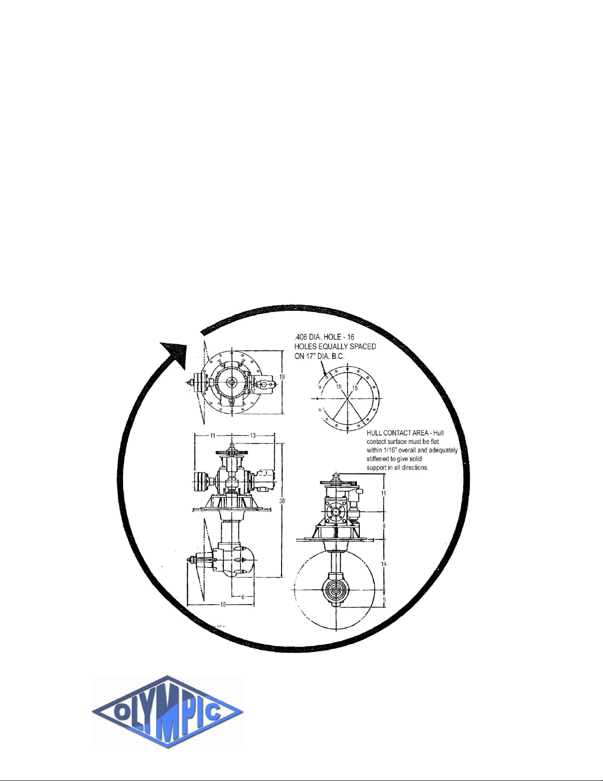
Description
The U360 Strut Drive is a propulsion system which
is equipped with a propeller strut which can be
rotated continuously through a full 360° so that full
thrust can be directed in any direction.
The drive consists of six functional assemblies: the
upper housing assembly, center housing assembly,
vertical housing assembly, lower housing
assembly, hydraulic system assembly, and power
steering assembly.
The drive is rated for 100 horsepower at 2400 RPM
continuous operation and for 130 horsepower at
2800 RPM intermittent operation. The output shaft
of the engine must rotate counter-clockwise when
looking at the end of the shaft. Drive weight is 370
pounds, including oil.
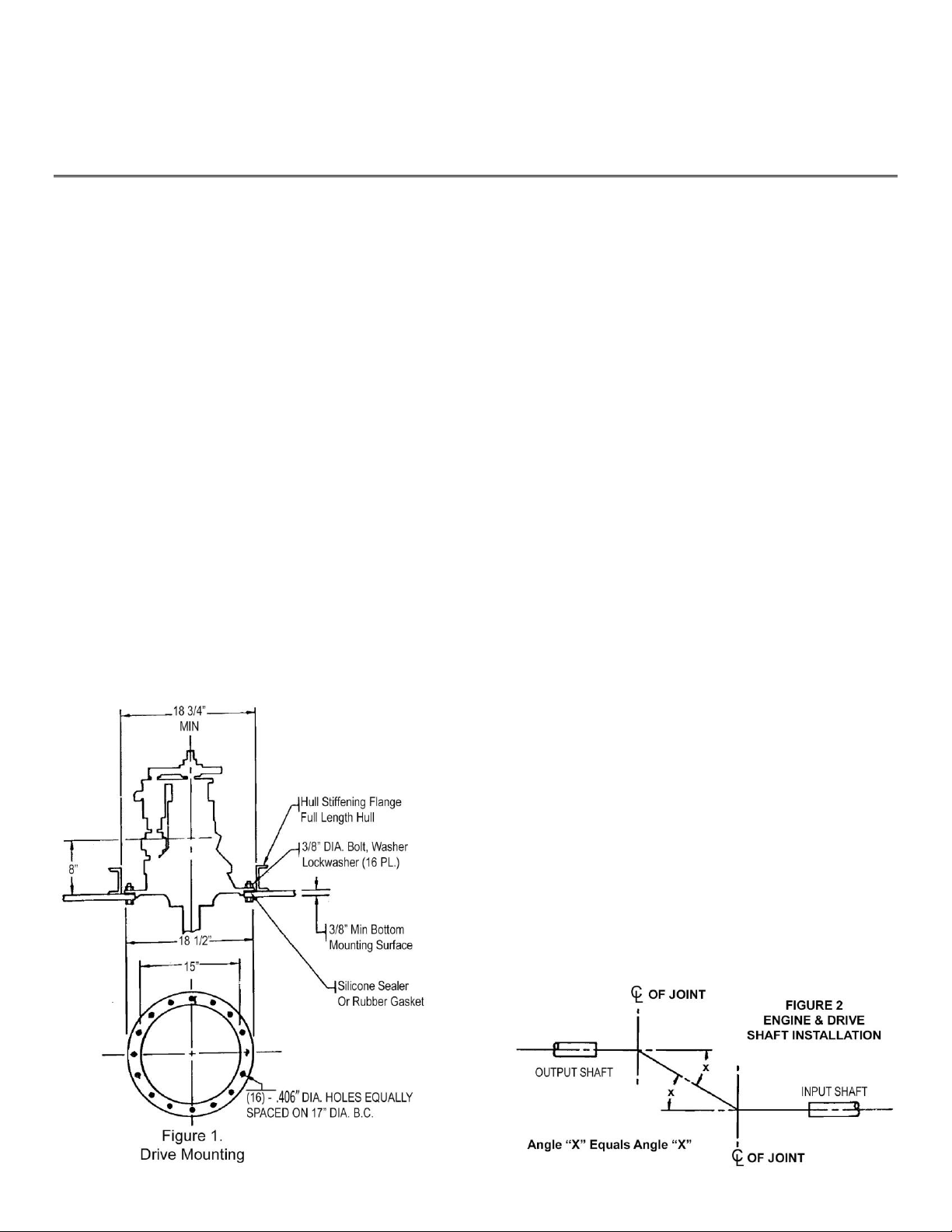
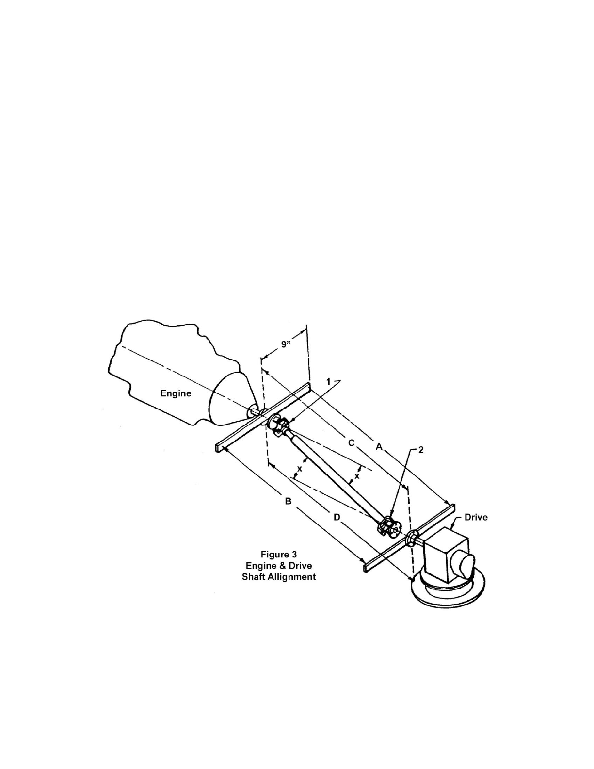
Power is transmitted from the engine to the drive
through a two-joint assembly incorporating a slip
joint together with a tubular connecting shaft. The
drive input flange must be equipped with a torsional
vibration damper. For trouble-free operation, the
drive and engine must be carefully aligned.
The propeller is driven through two sets of spiral
bevel gears. One set of gears is locked in the upper
housing and the second in the lower housing. The
total reduction ratio is 2:1.
The hydraulic system is comprised of a high-
pressure oil pump, oil filter, oil cooler, reservoir tank
and steering motor. The hydraulic system includes
the lubrication system and power steering system.
The high-pressure pump delivers constant power to
the steering motor at all times. The pump also
circulates the lubrication oil throughout the drive.
Steering ratio is 1:1 (360° rotation of the steering
wheel gives 360° rotation of the lower unit).
Normal operating pressure range of this system is
between 2 and 10 PSI, a higher pressure will
indicate a clogged oil filter only.

[5]
SECTION II
Installation Instructions
GENERAL
The U360 Steerable Strut Drive mounts on any flat
surface on the bottom of the vessel. The upper and
center housing assemblies are positioned inside
the hull and the vertical and lower housing
assemblies are submerged below the hull.
Attachment to the hull is accompanied by a
mounting flange which is sealed against water
leakage by a marine sealing compound or rubber
gasket and secured by mounting bolts. The
mounting surface must be adequately stiffened to
give solid support in all directions. Align drive so
that the shaft centerline coincides with the fore and
aft centerline of the engine before drilling hull for
mounting bolts. (Figure 1).
INSPECTION
Inspect each U360 Strut Drive Unit upon receipt as
follows:
1. Remove all packing.
2. Visually inspect for shipping damage to paint,
fittings and hoses.
3. Visually inspect for oil leakage.
INSTALLATION
Install each drive as follows:
1. Apply marine sealant liberally to mounting
surface on hull or apply rubber gasket.
2. Lower unit into position using a hoist,
positioning unit so the shaft centerline coincides
with fore and aft centerline of engine.
3. Install 3/8-inch diameter bolts, washers,
lockwashers and nuts.
4. Install drive shaft. Make sure that angles of both
joints are equal and lie in same plane. (Figure
2.)
NOTE: A method of aligning the engine and drive is
shown in Figure 3. Two accurate straight edges at
least 18 inches long and a tape measure are
required. Place the straight edges horizontally
along the face of the engine flange and the drive
flange. Measure distance A and B. Distances A and
B must be equal within 1/16” measured 9” out from
shaft centerline. If distances are not equal, move
the engine to accomplish alignment. Rotate straight
edges 90° and repeat measurements and
alignment. After the engine has been securely
anchored the measurements should be rechecked.
CAUTION: Do not attach oil filter to oil reservoir
tank. The weight of the filter will cause damage to
tank fittings.
5. Mount oil filter on bulkhead or suitable bracket.
Note arrow on side of filter for direction of flow.
6. Mount oil reservoir tank on a bulkhead or
suitable brackets.
7. Connect oil/hydraulic lines.
8. Install steering wheel assembly.
9. Mount pressure gauge on engine instrument
panel.
10. Connect hose from oil pressure gauge to port
on oil filter.

[6]
DRIVE SHAFT and UNIVERSAL JOINTS
The drive input shaft is provided with a Spicer*
rectangular type companion flange (Part No. 3-1-
604). This flange is securely mounted to the drive
input shaft on a Standard S.A.E 1 ¼ inch taper.
This flange matches the 1410 Series Spicer
universal joint assembly. The drive line must be
provided with a slip joint which is to be located at
the engine end of the shaft assembly. It is
recommended that the engine be installed so that
the operating angles of the universal joints are not
greater than 8° nor less than 2°. The standard drive
tube size is 3 inches outside diameter x 0.083 wall.
The maximum length of the drive line that can be
used for the recommended RPM and horsepower
measured between journal pivots is 65 inches, and
the minimum length is 12 3/8 inches.
Contact your local universal joint specialist for
recommendations on your installation and for
proper selection of the 1410 Series universal joints,
drive tube, and slip joint to adapt to your engine.
Your universal joint specialist or automotive
machine shop is equipped to assemble, weld, and
dynamically balance the drive line.
In using universal joints, the best results are
obtained with the joints operating at equal angles
and with the shafts parallel. The angle of both joints
must lie in the same plane. When assembling the
drive shaft, the slip joint must be installed so that
forks 1 and 2 lie in the same plane. (Figure 3.)

[7]
SECTION III
Propeller Installation & Removal Procedure
INSTALLATION
1. Inspect propeller shaft seal for leakage (oil in
drive).
2. Inspect propeller bore and prop shaft for
cleanliness.
3. Install 3/8” square x 3” long stainless steel key,
taking care that key is firmly seated in keyway
and not climbing up end of keyway.
4. Coat shaft and key with 50-50 mixture of white
lead and lube oil, or Never-Seeze Compound.
5. Install propeller to shaft, being sure that key
and keyway are properly aligned. Gently push
propeller all the way on taper until taper fits up.
Slide propeller off taper to check taper fit and
re-install propeller with a firm push, seating
taper.
6. Block propeller with soft wood close to hub and
install jam nut. Tighten to 150 foot pounds
torque.
7. Install lock-nut, holding jam nut and torque
against jam nut to 300-400 foot pounds torque.
8. Install new 5/32 x 1 ½ stainless steel cotter pin,
bending both legs around shaft.
REMOVAL (Always use puller)
1. Remove cotter pin.
2. Remove lock nut.
3. Slack jam nut about ½”.
4. Install puller using 3/8 –16 UNC hardened steel
puller bolts.
5. Block propeller close to hub (using soft wood)
against firm footing and tighten center puller
bolt. If propeller does not break loose by hand
with 15” long handle wrench, apply flame heat
to propeller hub, but do not heat so that metal
discolours. If propeller was properly installed, it
should be off the taper.
Corrosion Protection
To help prevent electrochemical corrosion,
each U360 drive is furnished with sacrificial
zinc anodes which must be replaced when
they are substantially “eaten away” to
maintain their effectiveness. Of course, these
anodes must not be painted over since their
effectiveness depends on their being in
contact with water.
It is suggested that additional zinc anodes be
attached to hulls of metal vessels to reduce
corrosion of the U360 drive and the hull
itself. Vessels used in fresh water may not
require additional anodes; but vessels used
in seawater usually require liberal quantities
of anodes to ward off costly corrosion.
Attachment of the drive to the hull must be
accomplished with fasteners which are close
to the drive and hull materials in the Galvanic
Series. Since the U360 drive is cast ductile
iron and most hulls are welded carbon steel,
the use of steel or stainless steel fasteners is
recommended.
DO NOT use copper alloy fasteners.

[8]
SECTION IV
Operating Instructions
GENERAL
For normal operating conditions, the U360
Steerable Strut Drive should be allowed to warm up
before running under full power. Waiting for the
engine to reach normal operating temperature with
drive clutch engaged should be sufficient.
LUBRICATION
Oil Capacity –18 quarts (U.S.) incl. oil reservoir
tank. The unit is filled by removing oil breather cap
located in oil reservoir tank.
Caution: An air pocket may form in the lower unit
during filling. After filling, idle the drive and check oil
pressure gauge to ensure that proper oil circulation
is taking place. After idling, recheck oil level.
Maintain oil level 3” from top of tank.
Note: Check oil level in oil reservoir tank daily.
Check for water in oil.
INITIAL START CHECKLIST
1. Before Running:
a. Drain plugs installed.
b. Drive unit lubricant level.
c. Leakage (oil lines and connections).
d. Fasteners on drive and drive shaft.
2. While Running:
a. Leakage (oil or water).
b. Oil pressure gauge indication.
3. After Running:
a. Drive unit lubricant level.
b. Water in lubrication oil.
c. Leakage (oil lines and connections).
d. Fasteners on drive unit and drive shaft.
4. Daily Operations:
a. Check drive unit oil level.
b. Monitor lubrication oil pressure gauge.
5. Every Month or 200 hours:
a. Drain and replace lube oil and filter.
Maintain oil level 3 inches from top of
tank.
6. Every 6 Months or 1000 hours:
a. Inspect power steering motor for wear or
leakage.
b. Inspect all hydraulic lines and fittings;
tighten or replace as required.
Water Temp:
Above 35°F Use 80 W 90 Gear Oil
Below 35°F Use SAE 10 W 30

[9]
Troubleshooting
Trouble
Probable Cause
Remedy
Vibration
Bent propeller
Straighten and balance propeller
Drive shaft installed improperly
Check that the universal joint forks are in the same plane
(bearing holes in the same direction)
Drive shaft has not been balanced
Have drive shaft dynamically balanced
Engine output shaft and drive input shaft
are not parallel
Adjust engine mount so that shafts are parallel
Worn drive shaft universal joints
Check condition of universal joints
Inadequate stiffness for drive mounting
Stiffen hull mounting flange and hull bottom
Engine mounting loose
Tighten engine mounts
Steering wheel locked
Low on oil
Check tank oil level. Inspect for broken oil lines and loose fittings
Pump not operating
Filter clogged
Air leak in suction line
Repair pump
Replace filter element
Check fittings and tighten where required
Suction hose collapsed
Replace suction hose
Lower unit does not steer
Obstruction jamming lower unit
Remove obstruction
Steering motor key on output shaft
sheared
Remove motor and replace key
Oil pressure gauge does not
respond at above 1000 RPM
Low oil level
Add oil to maintain proper level
Pump not operating
Repair pump as required
Oil leakage
Inspect for broken oil lines and loose fittings
Oil pressure gauge indicates
excessive pressure
Filter clogged
Replace filter element
Pinched or obstructed oil line
Remove obstruction
Oil level drops
Oil leakage
Inspect oil lines and fittings
Propeller shaft seal damaged
Inspect and replace propeller shaft seal if required
Propeller does not turn
Shear pin broken
Replace shear pin
Oil discoloured
Water leakage
Inspect and replace propeller shaft seal
Tighten lower housing bolts
Inspect and replace vertical housing O-Ring seal

[10]
PARTS LIST
ITEM
PART NO.
QTY.
DESCRIPTION
1
5111
1
Bearing –roller
2
7-500-103
1
Cap –lower housing
3
7-500-253
1
Housing –center
4
7-500-289
2
Zinc anode
5
NO LONGER USED
6
7-500-114
1
Shaft –prop
7
6023
1
Dowel pin
8
7-500-258
1
Sleeve –spacer
9
7-500-267
1
Retainer
10
NO LONGER USED
11
7-500-131
1
Shim –lower
12
7-500-132
1
Gasket
13
NO LONGER USED
14
7-500-134
1
Gasket
15
7-500-150
2
Shim –input shaft
16
7-500-151
1
Shim –prop bearing carrier
17
7-500-152
1
Shim –lower cap
18
7-500-154
1
Carrier –input shaft bearing
19
7-500-261
1
Carrier –prop bearing
20
7-500-157
1
Spacer
21
7-500-159
1
Spool –seal
22
7-500-256
1
Housing –vertical
23
7-500-162
1
Shim –lower housing
24
7-500-163
1
Housing –lower
25
7-500-282
1
Bearing –thrust
26
7-500-294
1
Mount –pump & carrier bearing
27
7-500-299
1
Torque generator (keyed shaft)
28
7-500-257
1
Sleeve –seal wear
29
6020
6
Lock washer SS
30
6101
4
Cap screw SS (zincs)
31
7-500-191
1
Shaft –vertical
32
7-500-270
1
Shim –upper
33
6127
1
Retaining ring
34
7-500-297
1
Shaft –input
35
7-500-298
1
Housing –upper
36
7-500-273
1
Key –flat
37
6126
1
Nyflex coupling
38
7-500-211
1
Dowel pin
39
6102
1
Key
40
7-500-259
1
Ring excluder
41
6103
1
Spring pin
42
NO LONGER USED
43
6104
1
Key –flat
44
7-500-287
1
Key –flat
45
7-500-260
1
Pump
46
NO LONGER USED
47
7-500-272
1
Key
48
1012-24A
1
Key –prop SS
49
7-500-239
1
Gearset –lower
50
1-308-107
1
Gear –spur
51
7-500-295
1
Pinion –spur
52
1-308-109
1
Gear –spur
53
1-308-110
1
Pinion –spur
54
7-500-241
1
Gearset –upper
55
5101/5102
2
Bearing –tapered roller
56
5103/5104
1
Bearing –tapered roller
57
5105/5106
1
Bearing –tapered roller
58
5107/5108
1
Bearing –tapered roller
59
5001/5002
1
Bearing –tapered roller
60
5109/5110
1
Bearing –tapered roller
61
6105
12
Lock washer
ITEM
PART NO.
QTY.
DESCRIPTION
62
6106
2
Lock washer
63
5112
1
Bearing - needle
64
5113
1
Bearing –inner race
65
5114
1
Bearing
66
5115
1
Bearing
67
5122
2
O-Ring
68
7-500-274
2
Key –flat
69
6107
1
Dowel pin
70
7-500-285
1
Gasket
71
5123
2
O-Ring
72
5124
1
O-Ring
73
5125
1
O-Ring
74
5126
1
O-Ring
75
7-500-235
1
Coupling assy.
76
1010-6
1
O-Ring
77
6124
1
Pipe plug
78
5128
1
O-Ring
79
6125
1
Pipe plug
80
6108
1
Spring pin
81
5129
3
Seal –lip
82
5130A
1
Seal –lip
83
5118
2
Lock nut - bearing
84
5119
2
Lock washer –bearing
85
5120
1
Lock nut –bearing
86
NO LONGER USED
87
5121
1
Lock washer –bearing
88
6122
1
Retaining ring
89
NO LONGER USED
90
1012-25
1
Prop nut
91
2152
1
Flange-companion
92
6109
1
Nut-Hex
93
5131
2
Seal-lip
94
1029-19
1
Key –woodruff
95
6110
1
Pin –cotter
96
6111
1
Pin –cotter SS
97
6112
8
Cap Screw –hex
98
1012-26
1
Prop jam nut
99
6113
6
Cap screw –hex SS
100
6114
3
Cap screw –hex
101
6115
6
Cap screw –hex
102
6019
6
Cap screw –hex SS
103
6117
2
Cap screw –hex
104
6118
12
Cap screw –hex
105
6119
4
Cap screw –hex hd. SS
106
7-500-269
1
Bearing –thrust
107
NO LONGER USED
108
6138
8
Lock washer (not shown)
109
7-1000-146
3
Lock washer
110
6120
4
Cap screw-hex
111
6121
4
Lock washer
112
7-500-113
1
Cover –top
113
NO LONGER USED
114
1029-13
1
Retaining ring
115
2100
Hose set (not shown)
116
5116
1
Bearing –needle
117
5117
1
Bearing –inner race
118
7-500-118
1
Connector - steering
119
1030-11
1
Shear pin
120
7-500-302
1
Seal retainer –input shaft

[11]
This manual suits for next models
2
Table of contents
Popular DC Drive manuals by other brands

CENTENT
CENTENT CN0165 operating manual

FnL
FnL CRD Series Quick installation guide

Rockwell Automation
Rockwell Automation Allen-Bradley PowerFlex Series installation instructions

Truma
Truma Mover SE quick start guide

Kanguru
Kanguru BioSlider II user manual

Lenze
Lenze i510 protec Mounting and switch-on instructions