manuals.online logo
Brands
  1. Home
  2. •
  3. Brands
  4. •
  5. Omega Engineering
  6. •
  7. Power Supply
  8. •
  9. Omega Engineering iDRN-PS-1000 User manual

Omega Engineering iDRN-PS-1000 User manual

LN
+-
USA
MADE
IN
User’s Guide
www.omega.com
e-mail: [email protected]
®
®
Shop on line at
iDRN-PS-1000
UNIVERSAL SWITCHING POWER SUPPLY
Co pact DIN-Rail 24 Volt
Servicing North A erica:
USA: One Omega Drive, P.O. Box 4047
ISO 9001 Certified Stamford, CT 06907-0047
T L: (203) 359-1660 FAX: (203) 359-7700
e-mail: [email protected]
Canada: 976 Bergar
Laval (Quebec) H7L 5A1
T L: (514) 856-6928 FAX: (514) 856-6886
e-mail: [email protected]
For i ediate technical or application assistance:
USA and Canada: Sales Service: 1-800-826-6342 / 1-800-TC-OM GA®
Customer Service: 1-800-622-2378 / 1-800-622-B ST®
ngineering Service: 1-800-872-9436 / 1-800-USA-WH N®
T L X: 996404 ASYLINK: 62968934 CABL : OM GA
Mexico T L: (001)800-TC-OM GASM FAX: (001) 203-359-7807
n spañol: (001) 203-359-7803 e-mail: [email protected]
Servicing Europe:
Benelux: Postbus 8034, 1180 LA Amstelveen, The Netherlands
T L: +31 (0)20 6418405 FAX: +31 (0)20 6434643
Toll Free in Benelux: 0800 0993344
e-mail: [email protected]
Czech Republic: Rudé armády 1868, 733 01 Karviná 8
T L: +420 (0)69 6311899 FAX: +420 (0)69 6311114
e-mail: [email protected]
France: 9, rue Denis Papin, 78190 Trappes
T L: +33 (0)130 621 400 FAX: +33 (0)130 699 120
Toll Free in France: 0800406342
e-mail: [email protected]
Ger any/Austria: Daimlerstrasse 26, D-75392 Deckenpfronn, Germany
T L: +49 (0)7056 9398-0 FAX: +49 (0)7056 9398-29
Toll Free in Germany: 0800 TC-OM GASM
e-mail: [email protected]
United Kingdo : One Omega Drive
ISO 9002 Certified River Bend Technology Centre
Northbank, Irlam
Manchester M44 5 X United Kingdom
T L: +44 (0)161 777 6611 FAX: +44 (0)161 777 6622
Toll Free in the UK: 0800 488 488
e-mail: [email protected]
omega.com
OMEGAnetSM On-Line Service Internet e- ail
http://www.o ega.co info@o ega.co
It is the policy of OM GA to comply with all worldwide safety and MC/ MI regulations that apply. OM GA is constantly
pursuing certification of its products to the uropean New Approach Directives. OM GA will add the C mark to every
appropriate device upon certification.
The information contained in this document is believed to be correct but OM GA ngineering, Inc. accepts no liability
for any errors it contains, and reserves the right to alter specifications without notice.
WARNING: These products are not designed for use in, and should not be used for, patient connected applications.
This device is marked with the international caution symbol. It is important to read the Setup Guide before installing or
commissioning this device as it contains important information relating to safety and MC.
1. General Information and Features 2
2. Safety Considerations 3
3. Installation and Removal 4
3.1 Installation Clearance 5
3.2 Mounting on IN Rail 6
3.3 Removal of Unit 7
4. Input and Output Connections 8
4.1 Block iagram 8
4.2 Wiring for 115 Vac - Single Phase 9
4.3 Wiring for 230 Vac - Two Phase 10
5. Specifications 11
Input Power 11
Output Power 11
General 12
Wire Connections 12
6. imensions 13
7. Temperature erating Graph 14
CONTENTS
1
The compact i RN power supplies are designed to
supply well-regulated 24 volt C power to sensors,
signal conditioners, data acquisition systems and
high level logic equipment.
Significant i RN features include:
• Tested isolation, primary to output
• Recessed live parts and connector screws
• 35mm IN rail mounting
• Wide input voltage tolerances
• Protective varistor input shunt
• Input AC spike rejection with LC filters
• LE power-on lamp
• Over-temperature protection
• Short circuit protection
• Low-ripple, well-regulated design
Features
GENERAL INFORMATION AN FEATURES
1
2
SAFETY CONSI ERATIONS
2
3
This device is marked with the international Caution symbol. It is
important to read this manual before installing or commissioning this
device as it contains important information relating to Safety and EMC
(Electromagnetic Compatibility).
Unpacking & Inspection
Unpack the instrument and inspect for obvious shipping damage. o not attempt to
operate the unit if damage is found.
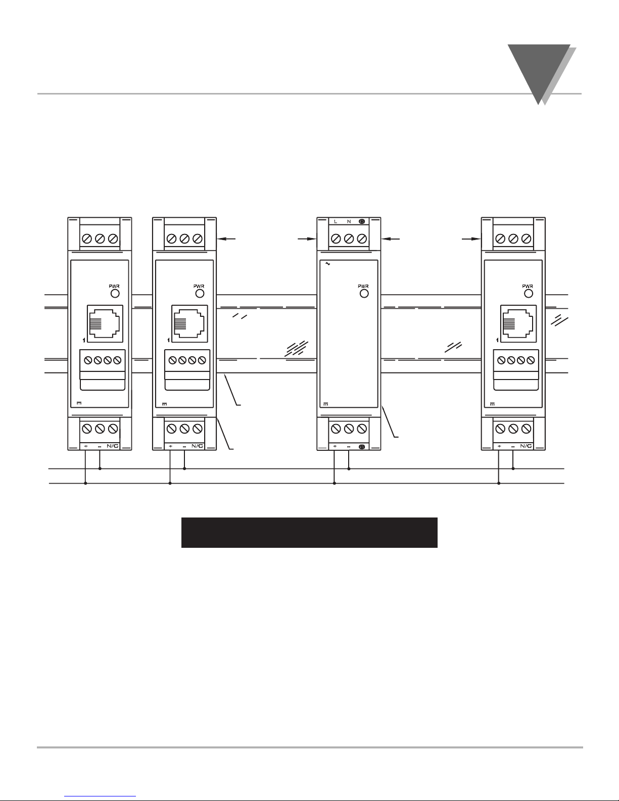
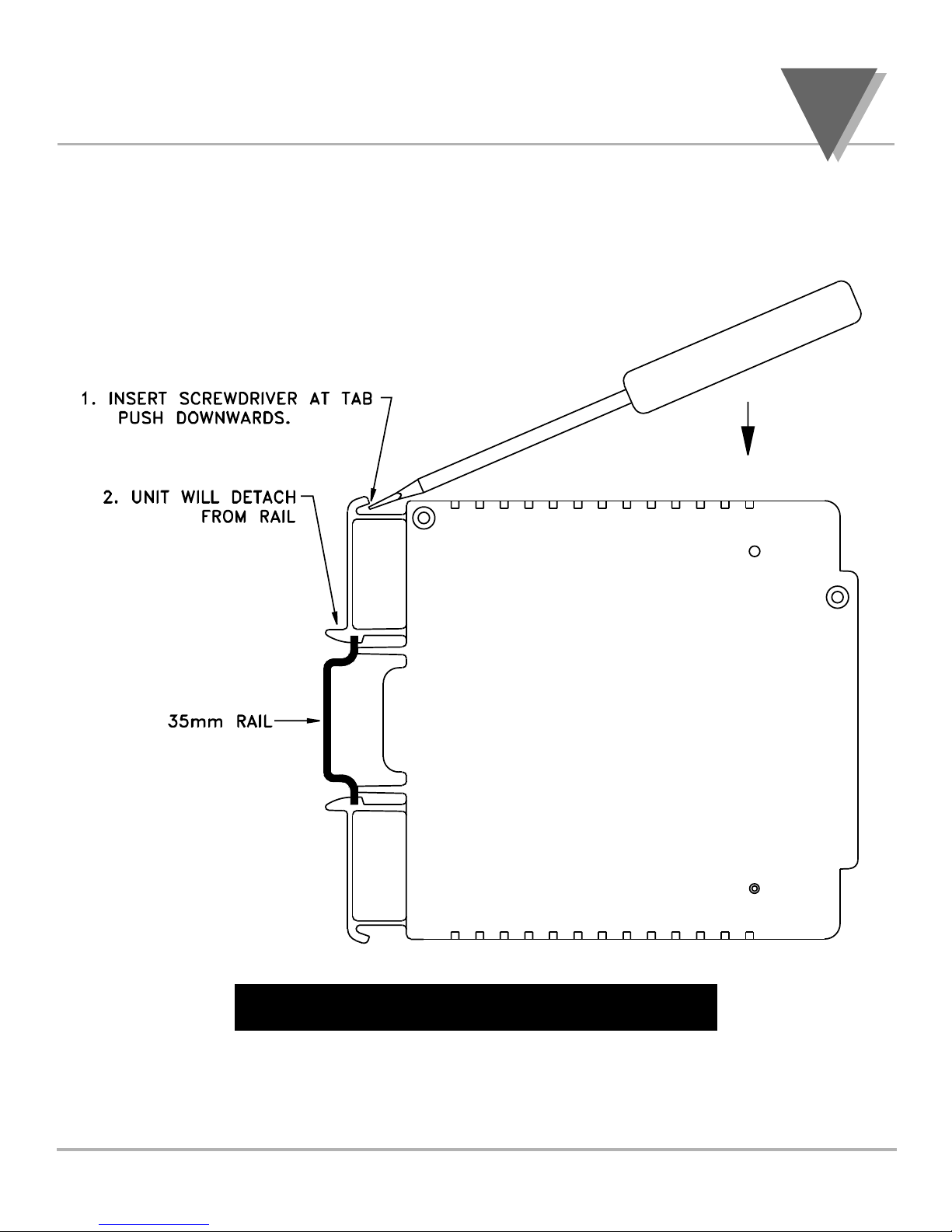
This instrument is a IN rail mount device. Installation of this instrument should be done
by Qualified personnel. In order to ensure safe operation, the following instructions
should be followed.
This instrument has no power-on switch. An external switch or circuit-breaker shall be included in the
building installation as a disconnecting device. It shall be marked to indicate this function, and it shall
be in close proximity to the equipment within easy reach of the operator. The switch or circuit-breaker
shall not interrupt the Protective Conductor (Earth wire), and it shall meet the relevant requirements
of IEC 947–1 and IEC 947-3 (International Electrotechnical Commission). The switch shall not be
incorporated in the mains supply cord.
Furthermore, to provide protection against excessive energy being drawn from the mains supply in
case of a fault in the equipment, an overcurrent protection device shall be installed.
• The Protective Conductor must be connected for safety reasons. Check that the
power cable has the proper Earth wire, and it is properly connected. It is not safe to
operate this unit without the Protective Conductor Terminal connected.
• o not exceed voltage rating on the label located on the top of the instrument
housing.
• Always disconnect power before changing signal and power connections.
• o not use this instrument on a work bench without its case for safety reasons.
• o not operate this instrument in flammable or explosive atmospheres.
• o not expose this instrument to rain or moisture.
• Unit mounting should allow for adequate ventilation to ensure instrument does not
exceed operating temperature rating.
• Use electrical wires with adequate size to handle mechanical strain and power
requirements. Install without exposing bare wire outside the connector to minimize
electrical shock hazards.
EMC Considerations
• Whenever EMC is an issue, always use shielded cables.
• Never run signal and power wires in the same conduit.
• Use signal wire connections with twisted-pair cables.
• Install Ferrite Bead(s) on signal wires close to the instrument if EMC problems
persist.
If a rail assembly is to be transported, then
disconnection, dismounting and separate
packing of the power supply is
recommended.
For units that must be shipped installed on
the rail, additional bracing to resist
transportation shocks is recommended.
o not attempt to install or connect to the
power supply when the mains are
energized.
Warning!
INSTALLATION AN REMOVAL
3
4
3.1 Installation Clearance
Ensure that there is enough room for mounting the power
supply unit. There should be a minimum of 1" [25mm] spacing
to allow sufficient air circulation for proper cooling.
Figure 3.1 — Mounting
INSTALLATION AN REMOVAL
3
DC POWER OUT
AC POWER IN
DC POWER IN
SIGNAL INPUT
DC POWER IN
SIGNAL INPUT
DC POWER IN
SIGNAL INPUT
IN RAIL
SIGNAL
CON ITIONER
MO ULES
24V-BUS
POWER SUPPLY
1" [25mm] 1" [25mm]
3.2 Mounting on DIN Rail
To install unit onto DIN Rail
1. Tilt unit, position mounting slot onto DIN Rail, as shown.
2. Push unit towards DIN Rail and it will snap into place.
Figure 3.2 — Mounting on 35mm DIN Rail
INSTALLATI N AND REM VAL
3
6
3
7
3.3 Removal of Unit
1. Insert flat screw-driver into tab and push downwards.
2. Unit will detach from DIN Rail.
Figure 3.3 — Removal of Unit
INSTALLATI N AND REM VAL
4
8
4.1 Block Diagram of Power Supply
Figure 4.1 — Block Diagram
4.2 Wiring
Warning: o not turn on the ac power to the power supply
unit until you have completed all output connections. Failure
to do so may result in injury!
This device must only be installed electrically by a specially
trained electrician with corresponding qualifications.
Warning: To avoid potential electric shock use National
Electrical Code (NEC) safety practices when wiring and
connecting this unit to a power source.
INPUT AN OUTPUT CONNECTIONS
4
9
INPUT AN OUTPUT CONNECTIONS
4.2 Wiring (Continued)
115Vac - Single phase power wiring
Figure 4.2— Wiring for 11 Vac - Single Phase
LN
+-
Output Voltage
(for shiel e wire
connections, if necessary)
Earth
FUSE 1
LINE
Switch
NEUTRAL
Earth
Switch
*
*
USE A SWITCH TO APPLY
+24V POWER TO THE LOAD,
IF THE CAPACITANCE OF
THE LOAD WILL DRAW MORE
THAN 7 AMPS AT TURN ON.
Earth
Return
+24 V
To Signal
Con itioner
Mo ules
Input Power
USE AWG 12-26 WIRE
4.3 Wiring (Continued)
230Vac - Two phase power wiring
Figure 4.3— Wiring for 230Vac - Two Phase
INPUT AN OUTPUT CONNECTIONS
4
10
LN
+-
Output Voltage
(for shiel e wire
connections, if necessary)
Earth
FUSE 1
L1
Switch
L2
Earth
FUSE 2
Switch
*
*
USE A SWITCH TO APPLY
+24V POWER TO THE LOAD,
IF THE CAPACITANCE OF
THE LOAD WILL DRAW MORE
THAN 7 AMPS AT TURN ON.
Earth
Return
+24 V
To Signal
Con itioner
Mo ules
Input Power
USE AWG 12-26 WIRE
SPECIFICATIONS
5
11
INPUT POWER
Input Voltage: 115 - 240Vac ±10%
Frequency: 50/60 Hz
Current: 0.400A @ 103Vac
0.190A @ 265Vac
Overvoltage Protection: 275 Volt Varistor
Overcurrent Protection: Fuse TR-5 800mA Time-lag / IEC 127-3
Input Wattage: 26 Watts
OUTPUT POWER
Output Voltage: 24Vdc ±2% @ 850mA (Resistive Load)
Output Wattage: 20 Watts*
* For higher output wattage greater than 20 watts follow the chart on
section 7, Figure 6.2.
Ripple: less than 100 mVrms
Operating Indicator: Front Panel LE
Short-Circuit/
Overload Protection: Current limiting with automatic short-
circuit protection and temperature
shutdown accomplished by the switcher.
Maximum number of
Signal Conditioner epends on module used and
modules powered: configuration (6-10 modules)
SPECIFICATIONS
5
12
GENERAL
Operating Temperature: 23° to 122°F(-5° to 50°C)
Storage Temperature: -40° to 176°F(-40° to 80°C)
Mounting: 35mm IN Rail
Size: Height: 3.55" (90mm)
Width: 0.99" (25mm)
epth: 4.38" (111mm)
Weight: 0.3 lbs. (0.14 kg)
Equipment Type: CLASS I
Overvoltage: CAT II
Pollution egree: 2
Insulation input to ouput: ielectric strength to 2500V transient
based on EN61010 for 265Vrms
working voltage
WIRE CONNECTIONS
Screw down wire clamps, AWG 12 to 26 (ferrules recommended
for stranded wire).
IMENSIONS
6
13
INPUT AC VOLTAGE / POWER OUTPUT
7
14
Example: If ambient is 50ºC, maximum wattage is 21W max. for
120-265Vac. If unit is operated at 21W at an input voltage of 100V,
the maximum ambient temperature allowed is 40ºC.
Figure 6.2 — Temperature Derating Graph
MAXIMUM POWER OUTPUT
INPUT AC
VOLTAGE
AMBIENT TEMPERATURE ºC
120V 265V
115V
110V
105V
100V
25ºC
-5ºC 30ºC 35ºC 40ºC 45ºC 50ºC
20W
24W 23W 22W 21W
AC INPUT CURRENT @ 100VAC INPUT
OUTPUT POWER AC CURRENT
20W 338mA
21W 355mA
22W 373mA
23W 392mA
24W 412mA
NOTES
15
NOTES
16
WARRANTY/DISCLAIMER
OM GA NGIN RING, INC. warrants this unit to be free of defects in materials and
workmanship for a period of 13 onths from date of purchase. OM GA Warranty adds an additional
one (1) month grace period to the normal one (1) year product warranty to cover handling and
shipping time. This ensures that OM GA’s customers receive maximum coverage on each product.
If the unit should malfunction, it must be returned to the factory for evaluation. OM GA’s Customer
Service Department will issue an Authorized Return (AR) number immediately upon phone or written
request. Upon examination by OM GA, if the unit is found to be defective it will be repaired or replaced
at no charge. OM GA’s WARRANTY does not apply to defects resulting from any action of the
purchaser, including but not limited to mishandling, improper interfacing, operation outside of design
limits, improper repair, or unauthorized modification. This WARRANTY is VOID if the unit shows
evidence of having been tampered with or shows evidence of being damaged as a result of excessive
corrosion; or current, heat, moisture or vibration; improper specification; misapplication; misuse or other
operating conditions outside of OM GA’s control. Components which wear are not warranted, including
but not limited to contact points, fuses, and triacs.
OMEGA is pleased to offer suggestions on the use of its various products. However,
OMEGA neither assu es responsibility for any o issions or errors nor assu es liability
for any da ages that result fro the use of its products in accordance with infor ation
provided by OMEGA, either verbal or written. OMEGA warrants only that the parts
anufactured by it will be as specified and free of defects. OMEGA MAKES NO OTHER
WARRANTIES OR REPRESENTATIONS OF ANY KIND WHATSOEVER, EXPRESSED OR
IMPLIED, EXCEPT THAT OF TITLE, AND ALL IMPLIED WARRANTIES INCLUDING ANY
WARRANTY OF MERCHANTABILITY AND FITNESS FOR A PARTICULAR PURPOSE ARE
HEREBY DISCLAIMED. LIMITATION OF LIABILITY: The re edies of purchaser set forth
herein are exclusive and the total liability of OMEGA with respect to this order, whether
based on contract, warranty, negligence, inde nification, strict liability or otherwise,
shall not exceed the purchase price of the co ponent upon which liability is based. In
no event shall OMEGA be liable for consequential, incidental or special da ages.
CONDITIONS: quipment sold by OM GA is not intended to be used, nor shall it be used: (1) as a
“Basic Component” under 10 CFR 21 (NRC), used in or with any nuclear installation or activity; or (2) in
medical applications or used on humans. Should any Product(s) be used in or with any nuclear
installation or activity, medical application, used on humans, or misused in any way, OM GA assumes
no responsibility as set forth in our basic WARRANTY/ DISCLAIM R language, and additionally,
purchaser will indemnify OM GA and hold OM GA harmless from any liability or damage whatsoever
arising out of the use of the Product(s) in such a manner.
RETURN REQUESTS / INQUIRIES
Direct all warranty and repair requests/inquiries to the OM GA Customer Service Department.
B FOR R TURNING ANY PRODUCT(S) TO OM GA, PURCHAS R MUST OBTAIN AN
AUTHORIZ D R TURN (AR) NUMB R FROM OM GA’S CUSTOM R S RVIC
D PARTM NT (IN ORD R TO AVOID PROC SSING D LAYS). The assigned AR number
should then be marked on the outside of the return package and on any correspondence.
The purchaser is responsible for shipping charges, freight, insurance and proper packaging to
prevent breakage in transit.
FOR WARRANTY R TURNS, please have
the following information available B FOR
contacting OM GA:
1. P.O. number under which the product
was PURCHAS D,
2. Model and serial number of the product
under warranty, and
3. Repair instructions and/or specific
problems relative to the product.
FOR NON-WARRANTY R PAIRS,
consult
OM GA for current repair charges. Have the
following information available B FOR
contacting OM GA:
1. P.O. number to cover the COST
of the repair,
2. Model and serial number of product, and
3. Repair instructions and/or specific
problems relative to the product.
OM GA’s policy is to make running changes, not model changes, whenever an improvement is possible.
This affords our customers the latest in technology and engineering.
OM GA is a registered trademark of OM GA NGIN RING, INC.
© Copyright 2002 OM GA NGIN RING, INC. All rights reserved. This document may not be copied,
photocopied, reproduced, translated, or reduced to any electronic medium or machine-readable form, in whole or in part,
without prior written consent of OM GA NGIN RING, INC.
USA
MADE
IN
PAT NT NOTIC : This product is covered by one or more of the following patents: U.S. Pat. No. Des. 336,895;
5,274,577 / Canada 2052599; 2052600 / Italy 1249456; 1250938 / France Brevet No. 91 12756 / Spain 2039150;
2048066 / UK Patent No. GB2 249 837; GB2 248 954 / Germany D 41 34398 C2
Used Under License. Other International Patents Pending.
M2540/0202
Where Do I Find Everything I Need for
Process Measure ent and Control?
OMEGA…Of Course!
Shop on line at www.o ega.co
TEMPERATURE
 Thermocouple, RTD & Thermistor Probes, Connectors, Panels & Assemblies
 Wire: Thermocouple, RTD & Thermistor
 Calibrators & Ice Point References
 Recorders, Controllers & Process Monitors
 Infrared Pyrometers
PRESSURE, STRAIN AND FORCE
 Transducers & train Gauges
 Load Cells & Pressure Gauges
 Displacement Transducers
 Instrumentation & Accessories
FLOW/LEVEL
 Rotameters, Gas Mass Flowmeters & Flow Computers
 Air Velocity Indicators
 Turbine/Paddlewheel ystems
 Totalizers & Batch Controllers
pH/CONDUCTIVITY

pH Electrodes, Testers & Accessories
 Benchtop/Laboratory Meters
 Controllers, Calibrators, imulators & Pumps
 Industrial pH & Conductivity Equipment
DATA ACQUISITION

Data Acquisition & Engineering oftware
 Communications-Based Acquisition ystems
 Plug-in Cards for Apple, IBM & Compatibles
 Datalogging ystems
 Recorders, Printers & Plotters
HEATERS

Heating Cable
 Cartridge & trip Heaters
 Immersion & Band Heaters
 Flexible Heaters
 Laboratory Heaters
ENVIRONMENTAL
MONITORING AND CONTROL
 Metering & Control Instrumentation
 Refractometers
 Pumps & Tubing
 Air, oil & Water Monitors
 Industrial Water & Wastewater Treatment
 pH, Conductivity & Dissolved Oxygen Instruments

Other Omega Engineering Power Supply manuals

Omega Engineering FAR-1 FAR-1 Series User manual

Omega Engineering

Omega Engineering FAR-1 FAR-1 Series User manual

Omega Engineering PSP User manual

Omega Engineering

Omega Engineering PSP User manual

Omega Engineering DIN-RAIL DRN-PS-750 User manual

Omega Engineering

Omega Engineering DIN-RAIL DRN-PS-750 User manual

Omega Engineering LDN-PS User manual

Omega Engineering

Omega Engineering LDN-PS User manual

Omega Engineering U24Y101 User manual

Omega Engineering

Omega Engineering U24Y101 User manual

Omega Engineering OM-420 User manual

Omega Engineering

Omega Engineering OM-420 User manual

Popular Power Supply manuals by other brands

Hioki 3269 instruction manual

Hioki

Hioki 3269 instruction manual

Eaton Power Xpert Series Installation and operation manual

Eaton

Eaton Power Xpert Series Installation and operation manual

Horizont Agrar hobbygard N 104271 Operating	 instruction

Horizont Agrar

Horizont Agrar hobbygard N 104271 Operating instruction

Antec EARTHWATTS EA-380 user manual

Antec

Antec EARTHWATTS EA-380 user manual

Vacon NX series Applications manual

Vacon

Vacon NX series Applications manual

KEPCO BOP 10-100GL quick start guide

KEPCO

KEPCO BOP 10-100GL quick start guide

Unit UDP6900 Series user manual

Unit

Unit UDP6900 Series user manual

Global Test Supply 1403 user manual

Global Test Supply

Global Test Supply 1403 user manual

B+K precision 1670A instruction manual

B+K precision

B+K precision 1670A instruction manual

HQ Power PSS6EMV26 user manual

HQ Power

HQ Power PSS6EMV26 user manual

Abus TVAC35500 user manual

Abus

Abus TVAC35500 user manual

KEPCO KLR SERIES quick start guide

KEPCO

KEPCO KLR SERIES quick start guide

Pegasus Astro Ultimate Powerbox operating instructions

Pegasus Astro

Pegasus Astro Ultimate Powerbox operating instructions

B+K precision 1601 instruction manual

B+K precision

B+K precision 1601 instruction manual

Corsair CMPSU-1000HX user manual

Corsair

Corsair CMPSU-1000HX user manual

B+K precision 1670 instruction manual

B+K precision

B+K precision 1670 instruction manual

Pegasus Astro POCKET POWERBOX ADVANCE product manual

Pegasus Astro

Pegasus Astro POCKET POWERBOX ADVANCE product manual

KEPCO HSP-A Series quick start guide

KEPCO

KEPCO HSP-A Series quick start guide

manuals.online logo
manuals.online logoBrands
  • About & Mission
  • Contact us
  • Privacy Policy
  • Terms and Conditions

Copyright 2025 Manuals.Online. All Rights Reserved.