3
WARNINGS:
1. This appliance is not intended for use by persons (
including children)
with reduced
physical,
sen
so
r
y
or mental
capabilities,
or lack of experience or
knowledge,
unless they have been given
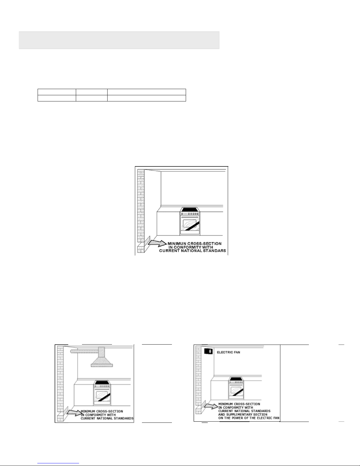
supervision
or
i
n
s
t
r
u
ctio
n
concerning
the use of the appliance by a person
responsible
for their safety. Children should be
supervised
to
ensure that they do not play with the a
pp
lianc
e
.
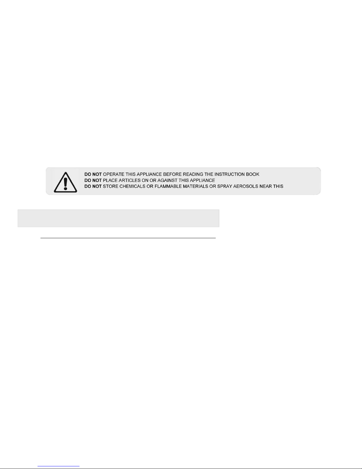
2.
DO NOT USE OR STORE FLAMMABLE MATERIALS IN THE APPLIANC STORAGE DRAWER OR NEAR THIS
APPLIANCE. DO NOT SPRAY AEROSOLS IN THE VACINITY OF THIS APPLIANCE WHILE IT IS IN OPERATION.
3.
DO NOT MODIFY THIS APPLIANCE. This appliance is not suitable for use with aftermarket lids or covers.
4.
WHERE THIS APPLIANCE IS INSTALLED IN MARINE CRAFT OR IN CARAVANS, IT SHALL NOT BE USED AS A SPACE
HEATER.
5. After
removing
the
packaging,
make sure to check if there is any damage to the appliance. If there
is
any
damage, never attempt to use the appliance and
immediately
contact your a
u
t
h
or
i
s
ed Service Centre.
As
packaging
materials can be
dangerous
to
children,
they need to be
collected
im
m
e
d
i
a
t
e
ly
and put out of
re
a
c
h
.
6. In certain
circumstances electrical appliances
may be a safety hazard. The unit MUST be
co
nn
ecte
d
to the
electrical
supply before
operation
to enable the
electronic ignition
to work. The e
l
ectrical connection
mu
s
t b
e
accessible
after
installation.
The appliance must be
electrically
isolated before any maintenance can
b
e
p
er
for
m
ed
.
7. Do not place heavy objects on this appliance
(cooktop
or door), use for storage or as a
c
u
tting surface, as sharp
edges can damage the surface. This appliance is designed for cooking only. If any damage such as chips
or cracks are seen in the glass, turn off all control knobs and do not use until the appliance has been
inspected by an authorised service person or replaced.
8. This appliance is designed for
domestic household
use only and for the cooking of
domestic
foo
d
products.
Use
as a
commercial
appliance will void the warranty. It should not to be used
outdoors
and must
be fully installed. Do
not use the appliance until fully installed. If this appliance is installed on a base, measures must be taken to prevent
the appliance from slipping from the base.
9. Damage can occur to bench tops if pots and pans are able to overlap the
b
ench top. This can result
i
n
heat
being
transferred
to the bench top. Ensure that correct sized pots & pans are used. Refer to guide
i
n
i
n
s
truct
i
ons.
10. Do not allow pot handles or
utensils
to be placed near gas burners in
operation,
as they
c
a
n
cause the handles to
become hot to touch. Always turn handles away when small children are nearby. It
i
s
recommended
that
children
are kept away from the
cooktop
at all
ti
me
s
.
11. Do not leave the
cooktop
while
cooking
with solid or liquid oils. There may be flaming up
in
c
ond
i
ti
on
s
of
extreme heating. Never pour water onto the flames
occurring
from oil.
Immediately
turn the
co
o
k
to
p o
ff and
cover the pan with a lid or fire blanket in order to smother the
f
l
am
e.
12. If the
electrical
supply cord is damaged, either when being
installed
or after
installation,
it must
be
replaced by
the
manufacturer,
its service agent or
similarly qualified
persons in order to prevent a
h
aza
rd
.
13. The appliance is not intended to be operated by means of an external timer or separate remote
cont
r
o
l
s
yst
em
.
14.
Electrical connection
must be made as per local wiring rules and
r
e
gu
l
a
t
i
on
s.. D o n o t
disconnect the
appliance
with wet hands or bare feet, and do not
disconnect
the power cord with extreme force. If the
elect
r
i
c
a
l
supply is
restricted,
means of all-pole
disconnection
must be
accessible
and
i
n
co
rp
o
r
ate
d in the fixed wiring in
accordance
with the wiring rules
.
15. Ensure that the kitchen is well
ventilated
or
mechanical ventilation
is in use while
cooking
on
th
e a
pp
lian
ce.
16. The
cooktop
and oven will become hot during and
directly
after use. Do not touch any
c
ompon
e
n
ts
during this
time, as they may be hot and can cause burns. To avoid burns young children should be kept a
w
a
y
.
Care should
be taken to avoid
touching
heating elements inside the
ov
e
n.
17. Cleaning may only be
commenced
on the appliance once it has cooled down and is turned off.
Fa
il
ur
e to clean
properly
can damage the unit. Do not use a steam jet or any other high pressure cleaning equipment
to
clean the
a
pp
lia
n
c
e
.
18. Do not use harsh abrasive cleaners or sharp metal scrapers to clean the glass surface as they
c
a
n
scratch the
surface, which may result in the glass
shattering.
Clean the glass using a
w
arm damp cloth (e
.g
.
dishcloth).
19. When the appliance is not being used, the knobs must be kept in the ‘OFF’
p
ositio
n
.
20. The appliance must be
installed
and put into
operation
by an
authorised
person under the
co
nd
iti
o
ns
provided by
the
manufacturer
in this manual. The
manufacturer
cannot be held
re
s
pon
si
ble for any damage
t
h
at
might occur
due to faulty
installation.
Do not modify this
ap
p
lia
n
ce.
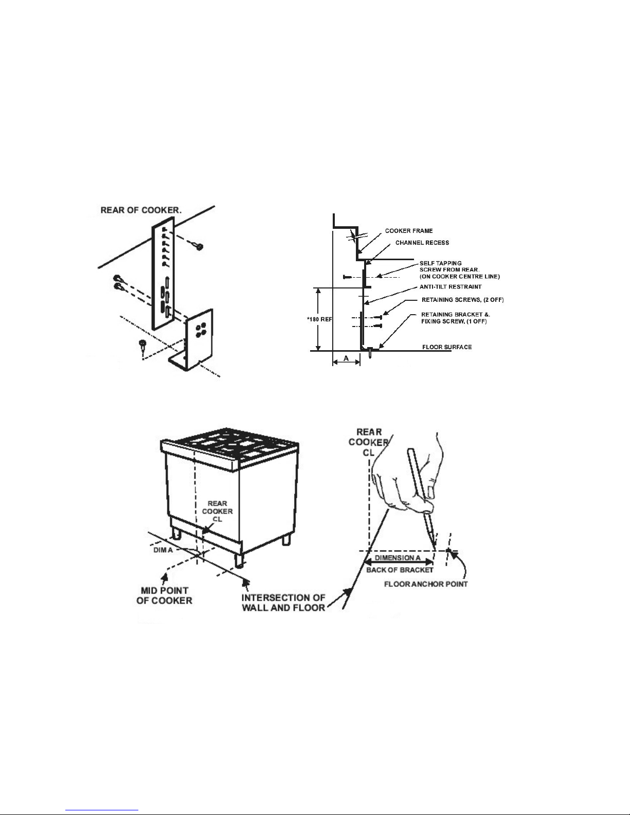
21. Use the
anti-tilt
kit to prevent the appliance from
accidentally
falling over
.