manuals.online logo
Brands
  1. Home
  2. •
  3. Brands
  4. •
  5. Videx
  6. •
  7. Power Supply
  8. •
  9. Videx 520MR User manual

Videx 520MR User manual

PrtCode:520MR.doc 18/05/2006 Rev.1.1
Power supply with built-in relay
Art.520MR
Alimentatore con relè incorporato
INSTALLATION INSTRUCTION ISTRUZIONI D’INSTALLAZIONE
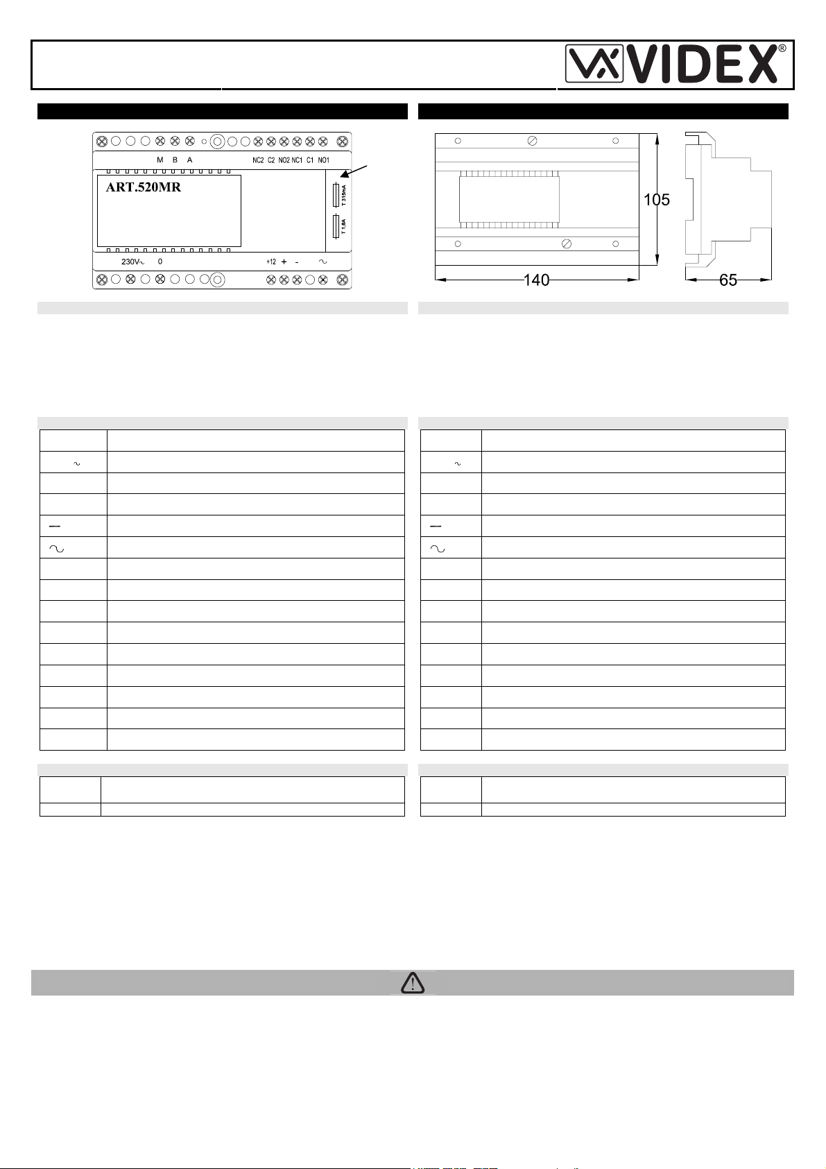
Fig.1 Fig.2
DESCRIPTION DESCRIZIONE
The Art.520MR is a regulated power supply with mains voltage 230Vac
50/60Hz and outputs 12Vdc, 8Vdc and 13Vac. The unit has a built-in en-
slavement relay controlled by the inputs M, Band A.
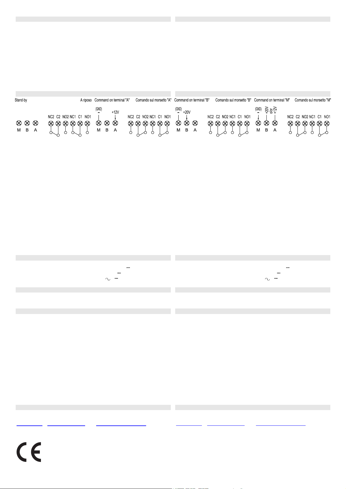
By providing a ground signal to terminal Mand a +20V signal to terminal B
or +12V signal to terminal A, the relay switches linking “normally open”
terminal (“NO1”, “NO2”) to “common” terminal (“C1”, “C2”).
L’Art.520MR è un alimentatore stabilizzato con ingresso 230Vac 50/60Hz
ed uscite 12Vdc, 8Vdc e 13Vac. L’unità incorpora un relè d’asservimento
comandato dagli ingressi M, Bed A.
Applicando un segnale di massa al morsetto Med un segnale +20V al
morsetto Bo +12V al morsetto A, il relè commuta chiudendo il morsetto
“normalmente aperto” (“NO1”, “NO2”) verso il morsetto “comune” (“C1”,
“C2”).
TERMINALS MORSETTI
Terminals Description
230V -0 Mains input 230Vac 50-60Hz
+12 +12Vdc 250mA max output
+ +8Vdc 250mA max output
Ground
13Vac 18VA max output
M Relay control – Ground
B Relay control – +20V signal
A Relay control – +12V signal
NC2 Relay normally closed contact 2
C2 Relay common contact 2
NO2 Relay normally open contact 2
NC1 Relay normally closed contact 1
C1 Relay common contact 1
NO1 Relay normally open contact 1
Morsetti Descrizione
230V -0 Ingresso d’alimentazione 230Vac 50-60Hz
+12 Uscita +12Vdc 250mA max
+ Uscita +8Vdc 250mA max
Massa
Uscita 13Vac 18VA max
M Comando relè – Massa
B Comando relè – Segnale +20V
A Comando relè – Segnale +12V
NC2 Relè contatto normalmente chiuso 2
C2 Relè contatto comune 2
NO2 Relè contatto normalmente aperto 2
NC1 Relè contatto normalmente chiuso 1
C1 Relè contatto comune 1
NO1 Relè contatto normalmente aperto 1
PROTECTIONS PROTEZIONI
T315 mA To protect from short circuits on +8Vdc or +12Vdc outputs.
T1,6 A To protect from short circuits on 13Vac outputs.
In case of fuses failure, proceed as follows to replace:
• Remove the mains;
• Holding the power supply with the left hand, pull the fuse holder (fig.1
ref.A) using the right hand;
• Check for damaged fuse and replace using an equal or equivalent one;
• Replace the fuse holder in the relevant housing by pushing it until the
top of the holder is in line with the top of the power supply;
• Restore the mains.
T315 mA Per protezione da corto circuito sulle uscite +12Vdc o
+8Vdc.
T1,6 A Per protezione da corto circuito sull’uscita 13Vac.
In caso di interruzione di uno dei fusibili, procedere come indicato di
seguito per la sostituzione:
• Togliere la tensione di rete;
• Tenendo fermo l’alimentatore con la mano sinistra, rimuovere il
coperchio porta-fusibili (fig.1 rif.A) tirandolo con forza verso l’alto
utilizzando la mano destra;
• Identificare il fusibile danneggiato e rimpiazzarlo con uno uguale o
equivalente;
• Riposizionare il coperchio porta-fusibili nella propria sede spingendolo
fino a che la sua parte superiore non è allineata con la parte superiore
dell’alimentatore;
• Ripristinare la tensione di rete.
CONNECTION TO MAINS COLLEGAMENTO ALLA RETE ELETTRICA
The system must be installed only by a competent engineer and according
to national rules in force and installation diagrams proposed (if provided),
in particular we recommend to:
• Connect the system to the mains through an all-pole circuit breaker
which shall have contact separation of at least 3mm in each pole and
shall disconnect all poles simultaneously;
• The all-pole circuit breaker shall be placed for easy access and the
switch shall remain readily operable.
La realizzazione dell’impianto deve essere eseguita esclusivamente da
personale qualificato e nel rispetto delle vigenti normative nazionali e degli
schemi di installazione proposti (se disponibili). In particolare si racco-
manda di:
• Collegare l’impianto alla rete elettrica tramite un dispositivo di interru-
zione omnipolare che abbia una distanza di separazione del contatto di
almeno 3mm per ciascun polo e che sia in grado di disconnettere tutti i
poli simultaneamente;
• Il dispositivo di interruzione omnipolare deve essere posizionato in un
luogo tale da consentirne un facile accesso in caso di necessità.
A
PrtCode:520MR.doc 18/05/2006 Rev.1.1
MOUNTING INSTALLAZIONE
• Remove the terminal side covers by unscrewing the retaining screws;
• Fix the power supply to a DIN bar or directly to the wall using two expan-
sion type screws;
• Switch off the mains using the circuit breaker mentioned above and then
make the connections as shown on the installation diagrams;
• Check the connections and secure the wires into the terminals;
• Replace the terminal covers and fix them using the relevant screws;
• When all connections are made, restore the mains.
• Rimuovere i coperchi copri-morsetti svitando le relative viti e tirandoli
verso l’alto;
• Fissare l’alimentatore su barra DIN o direttamente a parete utilizzando 2
viti ed i relativi tasselli ad espansione;
• Togliere la tensione di rete tramite il dispositivo sopra indicato ed
eseguire le connessioni come previsto dagli schemi proposti (la
connessione verso la rete va effettuata in base alla tensione disponibile
127 o 230Vac);
• Verificare che non vi siano errori di connessione e che i fili siano ben
serrati nei morsetti;
• Inserire a scatto i coperchi copri-morsetti e fissarli tramite le relative viti;
• Eseguiti tutti i collegamenti, dare tensione all’impianto.
BUILT-IN RELAY OPERATION FUNZIONAMENTO RELÈ INCORPORATO
Fig.3 Fig.4 Fig.5 Fig.6
Stand-by
Without command on terminals M,B and A the relay is in stand-by: C1
linked to NC1 and C2 linked to NC2.
Command on terminal “A”
With the “M” terminal connected to ground, the relay will switch when a
+12V signal on terminal “A”: the C1 terminal is linked to NO1 and C2 is
linked to NO2.
Command on terminal “B”
With the “M” terminal connected to ground, the relay will switch when a
+20V signal on terminal “B”: the C1 terminal is linked to NO1 and C2 is
linked to NO2.
Command on terminal “M”
With the “A” terminal is connected to +12V or the “B” terminal to +20V, the
relay switches when a ground is applied to terminal “M”: the C1 terminal is
linked to NO1 and C2 is linked to NO2.
A riposo
Senza comandi sui morsetti M, B ed A, il relè è a riposo: C1 chiude verso
NC1 e C2 chiude verso NC2.
Comando sul morsetto “A”
Con il morsetto “M” stabilmente collegato a massa, il relè commuta fino a
quando è presente il segnale +12V sul morsetto “A”: C1 chiude verso
NO1 e C2 verso NO2.
Comando sul morsetto “B”
Con il morsetto “M” stabilmente collegato a massa, il relè commuta fino a
quando è presente il segnale +20V sul morsetto “B”: C1 chiude verso
NO1 e C2 verso NO2.
Comando sul morsetto “M”
Con il morsetto “A” stabilmente collegato a +12V o il morsetto “B” a +20V,
il relè commuta fino a quando è presente un segnale di massa sul
morsetto “M”: C1 chiude verso NO1 e C2 verso NO2.
ELECTRICAL DATA DATI ELETTRICI
Mains voltage: 230Vac +6% -10% 50/60Hz
Output voltages: +12Vdc 250mA max (“+12”, “ “)
+8Vdc 250mA max (“+”,“ “)
13Vac 18VA max ( ,““)
Alimentazione: 230Vac +6% -10% 50/60Hz
Tensioni d’uscita: +12Vdc 250mA max (“+12”, “ “)
+8Vdc 250mA max (“+”,“ “)
13Vac 18VA max ( ,““)
MECHANICAL DATA DATI MECCANICI
Box: standard DIN 8 modules “A” type
Dimensions: 140x105x65mm
Contenitore: standard DIN 8 moduli tipo “A”
Dimensioni: 140x105x65mm
WORKING CONDITIONS CONDIZIONI DI LAVORO
Temperature: -10 +50 ºC
Humidity: 90% RM MAX
Protection degree: IP40
Temperatura: -10 +50 ºC
Umidità: 90% RM MAX
Grado protezione: IP40
CUSTOMER SUPPORT INFORMATION INFORMAZIONI ASSISTENZA CLIENTI
All Countries Customers UK Customers Clienti di tutti i Paesi Clienti UK
VIDEX Electronics S.p.A.
www.videx.it – [email protected]
Tel.+39 0734 631669
Fax +39 0734 632475
VIDEX Security LTD
www.videx-security.com
Tech Line 0191 224 3174
Fax 0191 224 1559
VIDEX Electronics S.p.A.
www.videx.it – [email protected]
Tel.+39 0734 631669
Fax +39 0734 632475
VIDEX Security LTD
www.videx-security.com
Tech Line 0191 224 3174
Fax 0191 224 1559
The product is CE marked demonstrating its conformity and is for distribution within all
member states of the EU with no restrictions.
This product follows the provisions of the European Directives
89/336/EEC & 92/31/EEC (EMC),
73/23/EEC (LVD) and 93/68/EEC (CE marking).
Il prodotto è marchiato CE a dimostrazione della sua conformità e può essere distribuito
liberamente all’interno dei paesi membri dell’unione europea EU.
Questo prodotto è conforme alle direttive Europee
89/336/EEC & 92/31/EEC (EMC),
73/23/EEC (LVD) e 93/68/EEC (Marcatura CE).

This manual suits for next models

2

Other Videx Power Supply manuals

Videx 521B User manual

Videx

Videx 521B User manual

Videx 521B User manual

Videx

Videx 521B User manual

Popular Power Supply manuals by other brands

Altinex V-MATRIX VM2218PS user guide

Altinex

Altinex V-MATRIX VM2218PS user guide

Yamaha PW4000 owner's manual

Yamaha

Yamaha PW4000 owner's manual

Kikusui PCR1000WEA user manual

Kikusui

Kikusui PCR1000WEA user manual

Evolveo GLOBAL LITE PLUS instruction manual

Evolveo

Evolveo GLOBAL LITE PLUS instruction manual

Wetekom MW650GS instruction manual

Wetekom

Wetekom MW650GS instruction manual

SECO-LARM Enforcer ST-1206-1.5A Brochure & specs

SECO-LARM

SECO-LARM Enforcer ST-1206-1.5A Brochure & specs

Emerson SmartPower 701P quick start guide

Emerson

Emerson SmartPower 701P quick start guide

Major Maxi 4 PSU manual

Major

Major Maxi 4 PSU manual

ABB Infinity S quick start guide

ABB

ABB Infinity S quick start guide

Thermal Dynamics CE PAK Master 75XL operating manual

Thermal Dynamics

Thermal Dynamics CE PAK Master 75XL operating manual

Elenco Electronics XP-650 instruction manual

Elenco Electronics

Elenco Electronics XP-650 instruction manual

Meanwell SHP-10K-HV Series installation manual

Meanwell

Meanwell SHP-10K-HV Series installation manual

turck PSU67-1P-1M-2M5-24150-IOL-F quick start guide

turck

turck PSU67-1P-1M-2M5-24150-IOL-F quick start guide

Altronix OLS350 installation guide

Altronix

Altronix OLS350 installation guide

Pintek PW-3063R instruction manual

Pintek

Pintek PW-3063R instruction manual

Rega TTPSU user manual

Rega

Rega TTPSU user manual

Antec VP650P user manual

Antec

Antec VP650P user manual

Alewings UniPower2B Usage manual

Alewings

Alewings UniPower2B Usage manual

manuals.online logo
manuals.online logoBrands
  • About & Mission
  • Contact us
  • Privacy Policy
  • Terms and Conditions

Copyright 2025 Manuals.Online. All Rights Reserved.