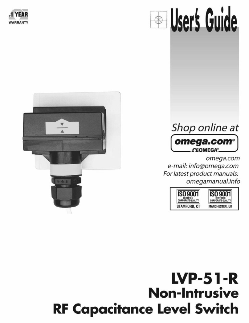
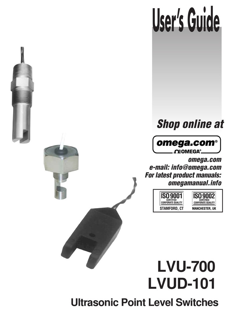
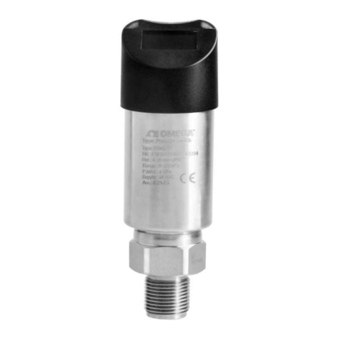
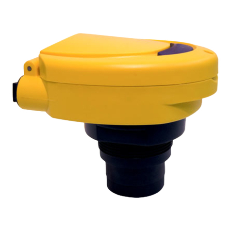
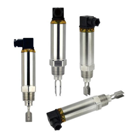
Omega LVF-210A Series User manual

1

2

3
INTRODUCTIONStepOne
AboutPoweredLevelSwitches:Thismanualcontainsinformationontwoseriesofpoweredlevelswitches;
Ultrasonic(LVU‐150series),TuningFork(LTU‐101Aseries)OpticLeak(LVF‐210Aseries)andCapacitance(LVC‐
152series).Theswitchesallfeaturetwooutputs:1)a4or20mAcurrentswitchand2)a60VASPSTdry
contactrelay.Allfourseriesaremanufacturedwiththermoplastics,includingthecable,makingthem
submersibleindesignandidealforcorrosiveapplications.PackagetheswitcheswitheitherOmega
Engineeringcontrollers(LVCN‐100seriesorLVCN‐120series)orinterfacedirectlytoanothercontrollerorPLC.
TableofContents
Specifications(Common):......................................................................................................................................4
UltrasonicSwitch(LVU‐150Series):...........................................................................................................5
TuningFork(LTU‐101ASeries):..................................................................................................................6
MaintenanceAlarm:......................................................................................................................7
OpticLeakDetection(LVF‐210Aseries):....................................................................................................8
CapacitanceSwitch(LVC‐152Series):......................................................................................................10
SafetyPrecautions:..............................................................................................................................................12
MakeaFail‐SafeSystem:..........................................................................................................................13
Installation:..........................................................................................................................................................14
ThroughWallInstallation:........................................................................................................................14
TopWallInstallation:...............................................................................................................................14
Electrical:..............................................................................................................................................................15
Wiring:..................................................................................................................................................................16
WiringtoaOmegaEngineeringController:.............................................................................................16
WiringtheRelayOutput:.........................................................................................................................17
WiringasaP‐ChannelorN‐ChannelOutput:..........................................................................................18
Maintenance:.......................................................................................................................................................19
Cleaningprocedure:.................................................................................................................................19
LTU‐101ASeriesMaintenanceAlarm:.....................................................................................................19
TestingtheInstallation:...........................................................................................................................20

4
SPECIFICATIONS(common)StepTwo
CommonSpecifications:
Orientation: Universal
Accuracy:±1mminwater
Repeatability:±0.5mminwater
Supplyvoltage:12‐36VDC
12‐30VDC(LTU‐101Aonly)
Consumption:25mAmaximum
Contacttype:(1)SPSTrelay
Contactrating:60VA
Contactoutput:SelectableNO/NC
Processtemp.:F:‐40°to176°
C:‐40°to80°
Pressure: 150psi(10bar)@25°C.,derated
@1.667psi(.113bar)per°C.
above25°C.
Sensorrating:NEMA6(IP68)
Cabletype: 4‐conductor,#22AWG(shielded)
Cablelength:10'(3m)‐Standard
25'(7.6m)or50'(15.2m)‐Special
Processmount:3/4"NPT(3/4”G/R)
Classification:Generalpurpose
Mount.Gasket:FKM(Gversiononly)
CEcompliance:EN61326EMC/EN61010‐1safety

5
SPECIFICATIONS(ultrasonic)StepTwo
UltrasonicSwitch(LVU‐150series):TheUltrasoniclevelswitchgeneratesa1.5MHzultrasonicwavefroma
miniaturepiezoelectrictransducerlocatedononesideofthegapinitssensingtip.Anotherpiezotransducer
locatedontheothersideofthegapactsasamicrophone,pickingupthesound.Whenliquidentersthegapin
thesensingtip,theaudiolevelchanges.
LVU‐152‐R&LVU‐153‐RLVU‐150‐R&LVU‐151‐R
LVU‐152‐G‐R&LVU‐153‐G‐RLVU‐150‐G‐R&LVU‐151‐G‐R
Thesensorshouldbeinstalledsothattheliquidwilldripoutofthegapwhenthesensorbecomesdry.
LVU‐150SeriesSpecifications:
Sensormaterial:‐150/‐152:PP
‐151/‐153:PFA
Cablejacketmat’l:‐150/‐152:PP
‐151/‐153:PFA
Configurations:
Part
NumberLengthMaterial
(body)
Material
(cable)
Cable
Length
LVU‐150‐RShort(3”)PolypropylenePolypropylene10’
LVU‐150‐G‐RShort(3”)PolypropylenePolypropylene10’
LVU‐151‐RShort(3”)PFAFEP10’
LVU‐151‐G‐RShort(3”)PFAFEP10’
LVU‐152‐RLong(4.5”)PolypropylenePolypropylene10’
LVU‐152‐G‐RLong(4.5”)PolypropylenePolypropylene10’
LVU‐153‐RLong(4.5”)PFAFEP10’
LVU‐153‐G‐RLong(4.5”)PFAFEP10’
Note:allultrasoniclevelswitchesareavailablewithlongerlengthscableof25’and50’.For25’ofcable,add
(‐25)totheendofthepartnumberandfor50’ofcable,add(‐50)totheendofthepartnumber.Example,
LVU‐150‐R‐25willhave25’ofcable.

6
SENSORINFORMATION(tuningfork)StepThree
TuningForkSwitch(LTU‐101ASeries):TheTuningForkswitchoperatesatanominalfrequencyof400Hz.As
theswitchbecomesimmersedinaliquidorslurry,acorrespondingfrequencyshiftoccurs.Whenthe
measuredfrequencyshiftreachesthesetpointvalue,theswitchchangesstateindicatingthepresenceofa
liquidorslurrymedium.Foroptimumperformanceandproactivemaintenance,thesensorautomatically
adjustsforcoating,andifnecessary,outputsapreventativemaintenancealarm.
LTU‐101A‐R
LTU‐101A‐G‐R
Donotsqueezetheforkstogether.Doingsocoulddamageorbreakthesensorandvoidthewarranty.
WhenpoweringuptheLTU‐101Aseries,thestart‐upprocedurerequirestheswitchtocyclethroughawet
conditionfor1/2secondinordertodetermineaninitialresonance.
LTU‐101ASeriesSpecifications:
Sensormaterial:PPS(glassfill)
FKMcablegrommet
Maint.alarm:NPNtransistor,10mAmax.
Cablejacketmat’l:PP
Cabletype:5‐conductor,#24AWG
(shielded)
Configurations:
PartNumberMaterial
(body)
Material
(cable)
Thread
(insidexoutside)
LTU‐101A‐RPolyphenyleneSulfidePolypropylene¾”NPTx¾”NPT
LTU‐101A‐G‐RPolyphenyleneSulfidePolypropylene¾”Rx¾”G
Note:alltuningforklevelswitchesareavailablewithlongerlengthscableof25’and50’.For25’ofcable,add
(‐25)totheendofthepartnumberandfor50’ofcable,add(‐50)totheendofthepartnumber.Example,
LTU‐101A‐R‐25willhave25’ofcable.

7
SENSORINFORMATION(tuningfork)StepThree
MaintenanceAlarm(LTU‐101AseriesTuningForkonly):Foroptimumperformanceandproactive
maintenance,thesensorautomaticallyadjustsforcoating,andifnecessary,outputsapreventative
maintenancealarm.TheYellowwireisaNPNtransistordesignedtoswitchwhenabuild‐upofmaterial
preventsthetuningforkswitchfromoperatingatitsoperationalfrequency.UsetheYellowwiretoidentify
whentheTuningForkswitchrequirescleaning.TowirethemaintenanceoutputwiretoanLED,followthe
wiringdiagrambelow.TheYellowwireisconnectedtotheLEDanda2.2kΩresistorinseriesandreferenced
backtothe(+)ofthepowersupply.
SensorPower
[RED&BLKwires]/36VDCMax.
8±1mADry/22±1mAWet
RelayRating
[GRN&WHTwires]/60VA
MaintenanceAlarm
[YELwire]/NPNTransistor/10mAMax.
TowirethemaintenanceoutputwiretoaPLC,followthewiringdiagrambelow.TheYellowwireisconnected
tothePLCinputwitha10kΩresistorparalleltothePLCinputandthe(+)ofthepowersupply.
SensorPower
[RED&BLKwires]/36VDCMax.
8±1mADry/22±1mAWet
RelayRating
[GRN&WHTwires]/60VA
MaintenanceAlarm
[YELwire]/NPNTransistor/10mAMax.

8
SPECIFICATIONS(optic)StepTwo
OpticLeakDetectionSwitch(LVF‐210Aseries):TheOpticLeakDetectoruseprinciplesofopticalrefractionto
detectthepresenceorabsenceoffluid.Apulsedinfraredlightbeamisinternallygeneratedbyalight
emittingdiodeandaimedattheslantedopticaltipofthesensor.Ifthetipisdry,thelightbeambouncesata
90degreeangletoareceivingphototransistor,indicatingadrycondition.Ifthetipisimmersedinliquid,the
lightbeamwillrefractoutintotheliquidinsteadofbeingreflectedtothephototransistor,indicatingawet
condition.
TheLVF‐210Aseriesisdesignedasaleakdetectionswitch.Theswitchshouldbeinstalledin
applicationswhereundernormalconditions,itremainsawayfromtheliquidandwillonlycomeinto
contactduringaleak.
LVF‐212A‐R&LVF‐213‐RLVF‐210A‐R&LVF‐211A‐R
LVF‐212A‐G‐R&LVF‐213‐G‐RLVF‐210A‐G‐R&LVF‐211A‐G‐R
TheOpticLeakDetectorcannotdetectthepresenceorabsenceofspecularapplicationliquidsthat
reflectlight(suchasmilk),orviscousliquids(suchaspaint)thatformacoatingonthesensortip.

9
SPECIFICATIONS(optic)StepTwo
LVF‐210ASeriesSpecifications:
Sensormaterial:‐210A/‐212A:PP
‐211A/‐213A:PFA
Cablejacketmat’l:‐210A/‐212A:PP
‐211A/‐213A:PFA
Configurations:
Part
NumberLengthMaterial
(body)
Material
(cable)
CablesideSensorside
LVF‐210A‐RShort(3”)PolypropylenePolypropylene(3/4”NPT)(3/4”NPT)
LVF‐210A‐G‐RShort(3”)PolypropylenePolypropylene(3/4”R)(3/4”R)
LVF‐211A‐RShort(3”)PFAPFA(3/4”NPT)(3/4”NPT)
LVF‐211A‐G‐RShort(3”)PFAPFA(3/4”R)(3/4”G)
LVF‐212A‐RLong(4.5”)PolypropylenePolypropylene(3/4”NPT)(3/4”NPT)
LVF‐212A‐G‐RLong(4.5”)PolypropylenePolypropylene(3/4”R)(3/4”R)
LVF‐213A‐RLong(4.5”)PFAPFA(3/4”NPT)(3/4”NPT)
LVF‐213A‐G‐RLong(4.5”)PFAPFA(3/4”R)(3/4”G)
Note:allopticleakdetectionlevelswitchesareavailablewithlongerlengthscableof25’and50’.For25’of
cable,add(‐25)totheendofthepartnumberandfor50’ofcable,add(‐50)totheendofthepartnumber.
Example,LVF‐210A‐R‐25willhave25’ofcable.

10
SPECIFICATIONS(capacitance)StepTwo
CapacitanceSwitch(LVC‐152series):Thecapacitancelevelswitchgeneratesapulse‐waveradiofrequency
signalfromthecapacitanceelectrodelocatedinthesensingtipofeachsensor.Whenliquidcomesinto
contactwiththesensingtip,thecapacitanceasmeasuredbythesensorchangesbasedonthedielectric
constantoftheliquid.Theguardcircuitrejectsthenegativeeffectsofcoatingbuildupontheprobeby
eliminatingthecoatingsignalpathbetweentheactiveandreferenceelectrodes.
AvoidinstallingtheLVC‐152seriesinmetalfittingsandkeepthesensor6”awayfrommetalobjects.Itis
possibleforalargemetalobjecttoinfluencethesensor’soperation.
LVC‐152‐R
LVC‐152‐G‐R
Thesensor’soperationmayvarybasedonthedielectricpropertiesofvariousapplicationliquids.The
LVC‐152seriessensorisfactory‐calibratedtobeusedwithliquidswithadielectricvaluebetween20and
80.Liquidswithadielectricconstantlessthan20willnotbedetectedbyanLVC‐152seriessensor.
TableofCommonDielectricConstants:NOTE:Liquidswithadielectricconstantlessthan20willnotbe
detectedbyanLVC‐152serieslevelswitch.
Acetone .......................21
Acetoaldehyde .........22.2
Acetyl methyl hexyl
ketone .........................28
Alcohol ..............16 to 31
Ammonia ...........15 to 25
Acetic acid .......4.1 to 6.2
Butyl chloride ............9.6
Barium chloride ...9 to 11
Benzene .....................2.3
Benzine ......................2.3
Barium nitrate ............5.6
Bromine .....................3.1
Chlorobenzene ...4.7 to 6
Chlorotoluene ............4.7
Chloroform ......4.5 to 5.0
Chlorine, liquid .........2.0
Carbon tetrachloride .2.2
Cyan ..........................2.6
Cyclohexane methanol
...................................3.7
D.I. Water ..................20
Ethyl toluene .............2.2
Ethyl alcohol ..............23
Ethylene glycol ..........37
Ethylene oxide ...........14
Ethylene dichloride
...........................11 to 17
Ethylene chloride ....10.5
Ethyl acetate .............6.4
Ethyl salicylate .........8.6
Ethyl stearate ............2.9
Ethyl silicote ............ 4.1
Formic acid ............... 59
Ferric oleate .............. 2.6
Freon ........................ 2.2
Glycerine ................... 47
Glycol ........................ 30
Glycol nitrite ............. 27
Gasoline ............2 to 2.2
Hydrochloric acid .... 4.6
Isobutyric acid .......... 2.7
Isobutyl methyl ketone
.................................... 13
Jet fuel ...................... 1.7
Lead carbonate .......... 18
Lead nitrate ............... 38
Methyl salicylate ...... 9.0
Methanol ..................... 33
Methyl alcohol .. 33 to 38
Margarine, liquid
.......................... 2.8 to 3.2
Methyl acetate ............7.3
N-butyl formate ..........2.4
Nitrobenzene ..... 26 to 35
Nitrotoluene ................ 25
Naphthalene ..... 2.3 to 2.5
Oils, vegetable .................
Oils, mineral ....2.3 to 2.4
Oils, petroleum.................
Oleic acid ....................2.5
Propane, liquid
......................... 1.8 to 1.9
Potassium nitrate5.0 to 5.9
Potassium chloride ...5.0
Stearic acid ................2.3
Toluene .....................2.4
Trichloroethylene .....3.4
Trichloroacetic acid ..4.5
Terephthalic acid
..........................1.5 to 1.7
Thinner ......................3.7
Urea ...........................3.5
Vinyl chloride ....2.8 to 6
Vinyl alcohol ..1.8 to 2.0
Water, 20°C ...............80
Water, 100°C .............48
11
SPECIFICATIONS(capacitance)StepTwo
LVC‐152SeriesSpecifications:
Dielectricrange: >20constants
Conductiverange:>100miromhos
Sensormaterial:PP
Cablejacketmat’l:PP
Configurations:
Part
NumberLengthMaterial
(body)
Material
(cable)
CablesideSensorside
LVC‐152‐RLong(4.5”)PolypropylenePolypropylene(3/4”NPT)(3/4”NPT)
LVC‐152‐G‐RLong(4.5”)PolypropylenePolypropylene(3/4”R)(3/4”G)
Note:allcapacitancelevelswitchesareavailablewithlongerlengthscableof25’and50’.For25’ofcable,add
(‐25)totheendofthepartnumberandfor50’ofcable,add(‐50)totheendofthepartnumber.Example,
LVC‐152‐R‐25willhave25’ofcable.
TestingTip:TheLVC‐152seriessensorlooksforchangesincapacitancebaseduponthedielectricconstantof
theliquid.Althoughwaterhasahighdielectricconstant,thevolumeofacupofwaterwillnothaveenough
changeincapacitancetoswitchthesensorintoawetcondition.Onewaytoincreasethecapacitanceforthe
cupofwateristodipyourfingerintothecup.Thevolumeofwaterwithinyourbodywilladdtothewaterin
thecupandwillresultinthesensoridentifyingawetcondition.

12
SAFETYPRECAUTIONStepThree
AboutManual:PLEASEREADTHEENTIREMANUALPRIORTOINSTALLINGORUSINGTHISPRODUCT.This
manualincludesinformationonallmodelsofOmegaEngineeringPoweredLevelSwitches:LVU‐150series,
LTU‐101Aseries,LVF‐210AseriesandLVC‐152series.Pleaserefertothepartnumberlocatedonthesensor
labeltoverifytheexactmodelwhichyouhavepurchased.
User’sResponsibilityforSafety:OMEGAENGINEERINGmanufacturesawiderangeofliquidlevelswitches
andtechnologies.Whileeachofthetheseswitchesaredesignedtooperateinawidevarietyofapplications,
itistheuser’sresponsibilitytoselectaswitchmodelthatisappropriatefortheapplication,installitproperly,
performtestsoftheinstalledsystem,andmaintainallcomponents.Thefailuretodosocouldresultin
propertydamageorseriousinjury.
ProperInstallationandHandling:Becausethisisanelectricallyoperateddevice,onlyproperlytrainedstaff
shouldinstalland/orrepairthisproduct.Useapropersealantwithallinstallations.Neverovertightenthe
sensorwithinthefitting,beyondamaximumof80inch‐poundstorque.Alwayscheckforleakspriortosystem
start‐up.
MaterialCompatibility:TheLVU‐150seriesandLVF‐210Aseriessensorsareavailableintwodifferent
wettedmaterials.ModelsLVU‐150,LVU‐152,LVF‐210AandLVF‐212AaremadeofPolypropylene(PP).
ModelsLVU‐151,LVU‐153,LVF‐211AandLVF‐213AaremadeofPerfluoroalkoxy(PFA).TheLTU‐101Aseriesis
madeofPPS(40%glassfilled)andtheLVC‐152seriesismadeofPP.Makesurethatthemodelyouhave
selectediscompatiblewiththeapplicationliquid.Todeterminethechemicalcompatibilitybetweenthe
sensoranditsapplicationliquids,refertoanindustryreferencesuchastheCompassCorrosion.
WiringandElectrical:Thesupplyvoltageusedtopowerthesensorshouldneverexceedamaximumof36
voltsDC(30VDCforLTU‐101Aseries).Electricalwiringofthesensorshouldbeperformedinaccordancewith
allapplicablenational,state,andlocalcodes.
Flammable,ExplosiveandHazardousApplications:DONOTUSETHELVU‐150SERIES,LTU‐101ASERIES,
LFV‐210ASERIESorLVC‐152SERIESGENERALPURPOSESWITCHINHAZARDOUSLOCATIONS.
Warning
Theratingfortherelayis60VA.
OmegaEngineering’spoweredlevelswitchesarenotrecommendedforusewithelectricallycharged
applicationliquids.Formostreliableoperation,theliquidbeingmeasuredmayneedtobeelectrically
grounded.
Alwaysinstallthe¾”FKMgasketwithallversionsofthepoweredsensorswithmetric(G)threads.The
metric(G)threadedversionwillnotsealunlessthegasketisinstalled.

13
SAFETYPRECAUTIONStepThree
MakeaFail‐SafeSystem:Designafail‐safesystemthataccommodatesthepossibilityofswitchand/orpower
failure.OMEGAENGINEERINGrecommendstheuseofredundantbackupsystemsandalarmsinadditionto
theprimarysystem.Addingaredundanthighlevelfloatswitchtothesystemisacosteffectivemeansto
preventcostlytankoverflows.
Allofthepoweredlevelsensorshaveasingleinternalrelay.Thenormallyopen(NO)ornormallyclosed(NC)
operationisuserselectedbasedonthedesiredsystemcontrol.Alwaysdesignafail‐safesystemthat
accommodatesforthepossibilityoffunctionaland/orpowerfailuretotheinstrument.The"normal"relay
stateiswheretherelaycoilisde‐energizedandtherelayindicatorisOFF.Therefore,ifpoweriscutOFFtothe
switchitwillde‐energizetherelay.Makesurethatthede‐energizedstateisthesafestateinyoursystem
design.Assuch,ifswitchpowerislost,apumpwillturnOFFifitisconnectedtothenormallyopensideofthe
relay.

14
INSTALLATION StepFour
ThroughWallInstallation:OmegaEngineering’s
poweredlevelswitchesmaybeinstalledthroughthe
top,sideorbottomofatankwall.Thesensorhas
male3/4"NPT(R/G)threadsoneithersideofa
15/16"wrenchflat.Thisenablestheusertoselect
thesensor’smountingorientation,installedoutside
ofthetankin,orinsideofthetankout.
TopWallInstallation:Thepoweredlevelswitchesmaybeinstalledthroughthetopwallofatank.Omega
Engineering’sleveltrackmountingsystemLVM‐10seriesisanin‐tankfittingwhichenablesuserstoinstallup
tofourOMEGAENGINEERINGsensorsofanytechnology,toanydepth,alongtheentirelengthoftrack.The
LVM‐10seriesmaybeinstalledthroughthetopwallofanytankusingastandard2"NPTtankadapter.Ifno
tanktopinstallationisavailable,OmegaEngineering'ssidemountbracket,LVM‐30,enablestheLVM‐10series
tobeinstalleddirectlytothesidewallofatank.DonotusethePFAbodiedsensorswithLVM‐10series.
OmegaEngineering’sLVM‐50seriesleveltrackmountingsystemisanin‐tankfittingwhichenablesusersto
installoneOMEGAENGINEERINGsensor,ofanytechnology,toaspecificdepth.TheOmegaEngineering
sensormaybeinstalledontothe3/4"NPTadapterattheendoftheLVM‐50series.TheLVM‐50seriesmaybe
installedthroughthetopwallofanytankusingastandard2"NPTtankadapter.OmegaEngineering'sside
mountbracket,modelLVM‐30,mayalsobeusediftopwallinstallationisnotavailable.

15
ELECTRICALStepFive
SupplyVoltage:Thesupplyvoltagetothepoweredlevelswitchshouldneverexceedamaximumof36VDC
(30VDCwithLTU‐101Aseries).OmegaEngineeringcontrollershaveabuilt‐in13.5VDCpowersupplywhich
providespowertoallofOmegaEngineering’selectricallypoweredsensors.Alternativecontrollersandpower
supplies,withaminimumoutputof12VDCuptoamaximumoutputof36VDC(30VDCwithLTU‐101A
series),mayalsobeusedwiththepoweredlevelswitch.
RequiredCableLength:Determinethelengthofcablerequiredbetweenthepoweredlevelswitchandits
pointoftermination.Allowenoughslacktoensuretheeasyinstallation,removaland/ormaintenanceofthe
sensor.Thecablelengthmaybeextendeduptoamaximumof1000feet,usingawell‐insulated,14to20
gaugeshieldedfourconductorcable.
WireStripping:Usinga10gaugewirestripper,carefullyremovetheouterlayerofinsulationfromthelast1‐
1/4"ofthesensor'scable.Unwrapanddiscardtheexposedfoilshieldfromaroundthesignalwires,leaving
thedrainwireattachedifdesired.Witha20gaugewirestripper,removethelast1/4"ofthecolored
insulationfromthesignalwires.
SignalOutputs(Currentsensing):Thestandard
methodusedbyOmegaEngineeringcontrollers;this
technologyusesonlytwowires(RedandBlack).The
sensordraws5mAwhenitisdry(8mAwithLTU‐101A
series),and22mAwhenwet.NC/NOstatusmustbe
setbythecontroller.TheWhiteandGreenwiresare
notused.
SignalOutput(Relayswitching):Allowsthesensortoswitchasmallloadonoroffdirectly,usinganinternal
1Arelay(60VAC/60VDC).Thesensorusestherelayandfeatures4wires(red,black,whiteandgreen)anda
shieldwire.TheNO/NCstatusissetbythepolarityofthevoltagefeedingtheredandblackwires.Thegreen
wireisthecommonfortherelayandthewhitewireistheNOorNC,dependingonthepolarityofredand
black.
NormallyOpenWiring:
NormallyClosedWiring:

16
WIRING StepSix
WiringtoaOMEGAENGINEERINGController
LVCN‐120SeriesController(4or20mAoutput):
LVCN‐120Shown
LVCN‐100SeriesController(4or20mAoutput):
LVCN‐20shown
SwitchingInductiveLoads:Theuseofsuppressors(snubbers)isstronglyrecommendedwhenswitching
inductiveloadstopreventdisruptingthemicroprocessor’soperation.Thesuppressorsalsoprolongthelifeof
therelaycontacts.SuppressioncanbeobtainedwithacatchdiodeforDCcircuitsandaresistor‐capacitor(RC)
forACcircuits.
CatchDiode
Alwaysusestepperrelaysbetweenthesensorandexternalloads.
ForDCcircuitsuseacatchdiodesuchas1N4148,shownonleft.
RefertothefollowingcircuitsforRCnetworkassemblyandinstallation:
ChooseRandCasfollows:
R:0.5to1Ohmsforeachvoltacrossthecontacts
C:0.5to1μFforeachampthroughclosedcontacts
Notes:
1. Usecapacitorsratedfor250VAC.
2. RCnetworksmayaffectloadreleasetimeofsolenoidloads.Check
toconfirmproperoperation.
3. InstalltheRCnetworkatthemetersrelayscrewterminals.AnRC
networkmayalsobeinstalledacrosstheload.Experimentforbest
results.

17
WIRING(continued)StepSix
WiringtheRelayOutput:Thesensorrequires12‐36VDC(30VDCmax.forLTU‐101Aseries)powerto
operatethesensorandswitchtherelay.AllillustrationsbelowidentifyaDryswitchstateasthenormal
positionoftherelay.
SwitchingaNormallyOpenDCLoad:
TheRedwireconnectstoPositive(+)ofthepower
supplyandtheBlackwireconnectstoNegative(‐).
TheLOADcanbeattachedtoeithertheGreenor
Whitewires.Completethecircuitbyconnectingthe
Greento(+)VDCpowerorWhiteto(‐)VDCpower
(seeillustrationbelow).
SwitchingaNormallyClosedDCLoad:
TheBlackwireconnectstoPositive(+)ofthepower
supplyandtheRedwireconnectstoNegative(‐).The
LOADcanbeattachedtoeithertheGreenorWhite
wires.CompletethecircuitbyconnectingtheGreen
to(+)VDCpowerorWhiteto(‐)VDCpower(see
illustrationbelow).
SensorPower
[RED&BLKwires]/36VDCMax.
5±1mADry/22±1mAWet
8±1mADry(LTU‐101Aseriesonly)
RelayRating
[GRN&WHTwires]/60VA
SwitchingaNormallyOpenACLoad:
TheRedwireconnectstoPositive(+)oftheDCpower
supplyandtheBlackwireconnectstoNegative(‐).
TheLOADcanbeattachedtotheGreenwireandthe
HotoftheVACpower.ConnecttheWhitetothe
NeutraloftheVACpower(seeillustrationbelow).
SwitchingaNormallyClosedACLoad:
TheBlackwireconnectstoPositive(+)oftheDC
powersupplyandtheRedwireconnectstoNegative
(‐).TheLOADcanbeattachedtotheGreenwireand
theHotoftheVACpower.ConnecttheWhitetothe
NeutraloftheVACpower(seeillustrationbelow).
SensorPower
[RED&BLKwires]/36VDCMax.
5±1mADry/22±1mAWet
8±1mADry(LTU‐101Aseriesonly)
RelayRating
[GRN&WHTwires]/60VA

18
WIRING(continued)StepSix
WiringasaP‐ChannelorN‐Channeloutput:ThesensorcanbesubstitutedforeitheraP‐Channel(PNP,
sourcing)outputoraN‐Channel(NPN,sinking)output.
NormallyOpenDCLoadasaP‐ChannelOutput:
TheRedwireconnectstoPositive(+)ofthepower
supplyandtheBlackwireconnectstoNegative(‐).
TheGreenwireisjumpedtotheRedwirewhilethe
WhitewireisconnectedtotheLOAD.Jumperthe
LOADtotheNegative(‐)tocompletethecircuit.
NormallyClosedDCLoadasaP‐ChannelOutput:
TheBlackwireconnectstoPositive(+)ofthepower
supplyandtheRedwireconnectstoNegative(‐).The
GreenwireisjumpedtotheBlackwirewhilethe
WhitewireisconnectedtotheLOAD.Jumperthe
LOADtotheNegative(‐)tocompletethecircuit.
SensorPower
[RED&BLKwires]/36VDCMax.
(30VDCMax.forLTU‐101Aseries)
5±1mADry/22±1mAWet
8±1mADry(LTU‐101Aseriesonly)
RelayRating
[GRN&WHTwires]/60VA
NormallyOpenDCLoadasaN‐ChannelOutput:
TheRedwireconnectstoPositive(+)ofthepower
supplyandtheBlackwireconnectstoNegative(‐).
TheWhitewireisjumpedtotheBlackwirewhilethe
GreenwireisconnectedtotheLOAD.Jumperthe
LOADtothePositive(+)tocompletethecircuit.
NormallyClosedDCLoadasaN‐ChannelOutput:
TheBlackwireconnectstoPositive(+)ofthepower
supplyandtheRedwireconnectstoNegative(‐).The
WhitewireisjumpedtotheRedwirewhiletheWhite
wireisconnectedtotheLOAD.JumpertheLOADto
thePositive(+)tocompletethecircuit.
SensorPower
[RED&BLKwires]/36VDCMax.
(30VDCMax.forLTU‐101Aseries)
5±1mADry/22±1mAWet
8±1mADry(LTU‐101Aseriesonly)
RelayRating
[GRN&WHTwires]/60VA

19
MAINTENANCE StepSeven
General:Thepoweredlevelswitchrequiresnoperiodicmaintenanceexceptcleaningasrequired.Itisthe
responsibilityoftheusertodeterminetheappropriatemaintenanceschedule,basedonthespecific
characteristicsoftheapplicationliquids.
Cleaningprocedure:
1. Power:Makesurethatallpowertotheswitch,controllerand/orpowersupplyisdisconnected.
2. Switchremoval:Inallthrough‐wallinstallations,makesurethatthetankisdrainedwellbelowthe
sensorpriortoremoval.Carefully,removethesensorfromtheinstallation.
3. Cleaningtheswitch:Useasoftbristlebrushandmilddetergent,carefullywashthelevelswitch.Do
notuseharshabrasivessuchassteelwoolorsandpaper,whichmightdamagethesurfacesensor.Do
notuseincompatiblesolventswhichmaydamagethesensor'sPP,PFA,PVDForPPSplasticbody.
4. Sensorinstallation:FollowtheappropriatestepsofinstallationasoutlinedintheInstallation.
MaintenanceOutputtoLED(LTU‐101Aseries only):
TowirethemaintenanceoutputwiretoanLED,
followthewiringdiagrambelow.TheYellowwireis
connectedtotheLEDanda2.2kΩ resistorinseries
andreferencedbacktothe(+)ofthepowersupply.
MaintenanceOutputtoPLC(LTU‐101Aseries only):
TowirethemaintenanceoutputwiretoaPLC,follow
thewiringdiagrambelow.TheYellowwireis
connectedtothePLCinputwitha10kΩ resistor
paralleltothePLCinputandthe(+)ofthepower
supply.
SensorPower
[RED&BLKwires]/30VDCMax.
8±1mADry/22±1mAWet
RelayRating
[GRN&WHTwires]/60
VA
MaintenanceAlarm
[YELwire]/NPNTransistor/10mAMax.

20
MAINTENANCE(continued)StepSeven
Testingtheinstallation:
1. Power:Turnonpowertothecontrollerand/orpowersupply.
2. Immersingtheswitch:Immersethesensingtipinitsapplicationliquid,byfillingthetankuptothe
switchespointofactuation.Analternatemethodistoholdacupfilledwithliquiduptotheswitch'stip.
3. Test:Withtheswitchbeingfluctuatedbetweenwetanddrystates,theswitchindicatorlightinthe
controllershouldturnonandoff.Ifthecontrollerdoesn'thaveaninputindicator,useavoltmeteror
ammetertoensurethattheswitchproducesthecorrectsignal(seebelow).
4. Pointofactuation:Observethepointatwhichtherisingorfallingfluidlevelcausestheswitchto
changestate,andadjusttheinstallationoftheswitchifnecessary.
Example:TestingtheLVU‐150serieswithaMultimetersettoreadcurrent(mA).WhenwiredNO[Redto(+)],
themeterwillread5mA,±1mAwhendryandwillread20mA,±1mAwhenwet.
Example:TestingtheLVU‐150serieswithamultimetersettoreadresistance(ohms).WhenwiredNO[Redto
(+)],themeterwillreadO.Lwhendryandwillreadsomesmallamountofresistance(ex.0.2Ohms)whenwet.
This manual suits for next models
21
Table of contents
Other Omega Switch manuals

Omega
Omega PSW-850 SERIES User manual

Omega
Omega OM-ESW-105-POE User manual

Omega
Omega LVP-51-R User manual

Omega
Omega FLSW3400 Series User manual

Omega
Omega iServer MicroServer EIS-2B User manual

Omega
Omega LTUM1 Series User manual

Omega
Omega OM-ESW-105-POE User manual

Omega
Omega PSW2100 User manual

Omega
Omega LVCN700 Series User manual

Omega
Omega PSW1110 Series User manual
Popular Switch manuals by other brands

Gira
Gira 0144 30 operating instructions

3Com
3Com 3C17700 - SuperStack 3 Switch 4900 Getting started guide

Siemens
Siemens ASC10.51 Mounting instructions

Vivotek
Vivotek AW-FCT-050A-250 Quick installation guide

ZyXEL Communications
ZyXEL Communications XGS-4528F user guide

VICOR
VICOR PFC MegaPAC-EL user guide