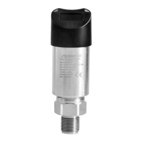
Omega LVP-51-R User manual

1

2

3
INTRODUCTIONStepOne
AboutNon‐IntrusiveRFCapacitanceTechnology:OMEGAENGINEERING'sLVP‐51‐Rlevelswitchgeneratesa
highradiofrequencysignalfromthecapacitanceelectrodeonthetanksideofeachsensor.Dependingonthe
thicknessofthetankwallandthematerialofwhichitismade,thereisaparticularminimumdielectricvalue
theelectrodemeasureswhenthereisnoliquidontheothersideofthetankwallfromthesensor.Whenliquid
isontheothersideofthewall,thedielectricvaluerises.
Aspartofinstallation,atwo‐stepcalibrationprocedureensuresthatthethresholdbetweenwetanddryisset
attheidealpointforyourparticulartankandapplicationfluid,withouttheuseofanyexternaltest
equipment.Thesensor’soperationandpointofactuationmayvarybasedonthedielectricpropertiesof
variousapplicationliquids,tankmaterialsandthicknesses.TheLVP‐51‐Rsensorisintendedtobeusedwith
liquidswithadielectricvaluebetween20and80.Duetoitsusercalibrationcapabilityitmaybeabletodetect
liquidsbelowadielectricconstantof20undercertainconditions,butthismustbeverifiedby
experimentation.
TableofContents
Specifications&Dimensions:.................................................................................................................................4
SafetyPrecautions:................................................................................................................................................5
MakeaFail‐SafeSystem:...........................................................................................................................6
Components:..............................................................................................................................................6
Installation:............................................................................................................................................................7
AttachfittingtoTank:................................................................................................................................7
MountSensorinFitting:............................................................................................................................7
Electrical:................................................................................................................................................................8
SignalOutput(currentsensing):................................................................................................................8
SignalOutput(relayswitching):.................................................................................................................9
Wiring:..................................................................................................................................................................10
WiringtoaOMEGAENGINEERINGController:........................................................................................10
SwitchingInductiveLoads:.......................................................................................................................10
WiringtheRelayOutput:.........................................................................................................................11
WiringasaP‐ChannelorN‐ChannelOutput:..........................................................................................12
Calibration:...........................................................................................................................................................13
Maintenance:.......................................................................................................................................................14
CheckingPointofActuation:...................................................................................................................................14
TestingtheSensor:..................................................................................................................................................14
Maintenance:..........................................................................................................................................................14

4
SPECIFICATIONS&DIMENSIONSStepTwo
Specifications:
Tankmounting: Non‐intrusive
Tankmat.comp.: Non‐metallic
Tankwallthick.: <1"(25mm)
Accuracy: ±1mminwater
Repeatability: ±0.5mminwater
Dielectricrange: >20constants
Conductiverange: >100µS/cm
Supplyvoltage: 12‐36VDC
Consumption: 25mAmaximum
Contacttype: (1)SPSTrelay
Contactrating: 60VA,1Amaximum
Contactoutput: SelectableNO/NC
Processtemp.: F:‐40°to176°
C:‐40°to80°
Enclosurerating: NEMA4X(IP65)
Enclosuremat.: PSO
Conduitentrance: Single,1/2"NPT
Bracketmaterial: LVP‐92:PP
LVP‐91:PE
Bracketmounting: 3Madhesive/plasticthermal
weld
Cablejacketmat.: PP
Cabletype: 4‐conductor,#22AWG
(shielded)
Cablelength: Standard:10'(3m)
Classification: Generalpurpose
CEcompliance: EN61326EMC
EN61010‐1safety
Dimensions(shownwithLVP‐91bracket):
DeratingCharts:

5
SAFETYPRECAUTIONStepThree
AboutManual:PLEASEREADTHEENTIREMANUALPRIORTOINSTALLINGORUSINGTHISPRODUCT.This
manualincludesinformationonallmodelsofOMEGAENGINEERINGNon‐IntrusiveRFCapacitanceLevel
Switch:LVP‐51‐R.Pleaserefertothepartnumberlocatedonthesensorlabeltoverifytheexactmodelwhich
youhavepurchased.
User’sResponsibilityforSafety:OMEGAENGINEERINGmanufacturesawiderangeofliquidlevelswitches
andtechnologies.Whileeachofthetheseswitchesaredesignedtooperateinawidevarietyofapplications,
itistheuser’sresponsibilitytoselectaswitchmodelthatisappropriatefortheapplication,installitproperly,
performtestsoftheinstalledsystem,andmaintainallcomponents.Thefailuretodosocouldresultin
propertydamageorseriousinjury.
ProperInstallationandHandling:Becausethisisanelectricallyoperateddevice,onlyproperlytrained
staffshouldinstalland/orrepairthisproduct.Theadhesiveonthefittingisfortemporaryinstallationonly.
Forpermanentinstallation,thefittingforthesensorshouldbewelded,glassedorstrappedtothetankitself
usingapprovedplasticweldingtechniques.DonotinstalltheLVP‐51‐Rsensoronametaltank,orwithin6"of
anymetalpipeorfitting.
MountingBracket:TheLVP‐51‐RsensormaybemountedinthePE(LVP‐91)orPP(LVP‐92)bracket.Make
surethatthefittingiscompatiblewiththetankitwillbeappliedto.
MaterialCompatibility:Thesensoritselfisnotdesignedtobeimmersed.Itshouldbemountedinsucha
waythatitdoesnotnormallycomeintocontactwithfluid.ItscaseismadeoutofPolysulfone(PSO).Referto
anindustryreferencesuchastheCompassCorrosionGuidetoensurethatcompoundsthatmaysplashonto
thecontrollerhousingwillnotdamageit.Suchdamageisnotcoveredbythewarranty.
WiringandElectrical:ThesupplyvoltageusedtopowertheLVP‐51‐Rsensorshouldneverexceeda
maximumof36voltsDC.Electricalwiringofthesensorshouldbeperformedinaccordancewithallapplicable
national,state,andlocalcodes.
Flammable,ExplosiveandHazardousApplications:TheLVP‐51‐Rswitchisnotratedforuseinhazardous
locations.RefertotheNationalElectricCode(NEC)forallapplicableinstallationrequirementsinhazardous
locations.DONOTUSETHELVP‐51‐RGENERALPURPOSESWITCHINHAZARDOUSLOCATIONS.
Warning
Theratingfortherelayis60VA.
DonotinstalltheLVP‐51‐Rlevelswitchonametallictank,orwithin6"ofanymetallicobject.Metalwill
adverselyaffectthedielectricsensitivityofthesensor.
OMEGAENGINEERING'sLVP‐51‐Rsensorsarenotrecommendedforusewithelectricallycharged
applicationliquids.Formostreliableoperation,theliquidbeingmeasuredmayneedtobeelectrically
grounded.

6
SAFETYPRECAUTION(capacitance)StepThree
MakeaFail‐SafeSystem:Designafail‐safesystemthataccommodatesthepossibilityofswitchand/orpower
failure.OMEGAENGINEERINGrecommendstheuseofredundantbackupsystemsandalarmsinadditionto
theprimarysystem.Addingaredundanthighlevelfloatswitchtothesystemisacosteffectivemeansto
preventcostlytankoverflows.
TheLVP‐51‐Rswitchhasasinglerelay.Thenormallyopen(NO)ornormallyclosed(NC)operationisuser
selectedbasedonthedesiredsystemcontrol.Alwaysdesignafail‐safesystemthataccommodatesforthe
possibilityoffunctionaland/orpowerfailuretotheinstrument.The"normal"relaystateiswheretherelay
coilisde‐energizedandtherelayindicatorisOFF.Therefore,ifpoweriscutOFFtotheswitchitwillde‐
energizetherelay.Makesurethatthede‐energizedstateisthesafestateinyoursystemdesign.Assuch,if
switchpowerislost,apumpwillturnOFFifitisconnectedtothenormallyopensideoftherelay.
Technology:Thenon‐intrusiveRFcapacitanceswitchdetectsthepresenceofliquidorairbymeasuringthe
conductiveordielectricvalueswhicharepresentinallmaterials.Anelectricalcapacitorisformedbetween
thelevelswitchandtheoutertankwall.Asliquidrisesandfallsagainsttheinnerwall,thecapacitanceeffectis
greatlyincreasedandthe60VASPSTrelaychangesstate.
Thesensor’soperationmayvarybasedonthedielectricpropertiesofvariousapplicationliquids.Liquids
withadielectricconstantlessthan20maynotbedetectedbyanLVP‐51‐Rsensor.
TableofCommonDielectricConstants:NOTE:Liquidswithaconductivityvalue>100µS/cmarefineif
coatingisnotanissue.Liquidswithadielectricconstantlessthan20willnotbedetectedbyanLVP‐51‐Rlevel
switch,dependingonconditions.
Acetone .....................21
Acetoaldehyde .......22.2
Acetyl methyl hexyl
ketone ........................28
Alcohol ........... 16 to 31
Ammonia ........ 15 to 25
Acetic acid .... 4.1 to 6.2
Butyl chloride ..........9.6
Barium chloride 9 to 11
Benzene ...................2.3
Benzine ....................2.3
Barium nitrate ..........5.6
Bromine ...................3.1
Chlorobenzene . 4.7 to 6
Chlorotoluene ..........4.7
Chloroform ....4.5 to 5.0
Chlorine, liquid .......2.0
Carbon tetrachloride 2.2
Cyan ........................2.6
Cyclohexane methanol
..................................3.7
D.I. Water .................20
Ethyl toluene ...........2.2
Ethyl alcohol ............23
Ethylene glycol ........37
Ethylene oxide ..........14
Ethylene dichloride
..........................11 to 17
Ethylene chloride .. 10.5
Ethyl acetate ............ 6.4
Ethyl salicylate ........ 8.6
Ethyl stearate .......... 2.9
Ethyl silicote ........... 4.1
Formic acid .............. 59
Ferric oleate ............ 2.6
Freon ....................... 2.2
Glycerine .................. 47
Glycol ....................... 30
Glycol nitrite ............ 27
Gasoline ...........2 to 2.2
Hydrochloric acid ... 4.6
Isobutyric acid ........ 2.7
Isobutyl methyl ketone
...................................13
Jet fuel .....................1.7
Lead carbonate .........18
Lead nitrate ...............38
Methyl salicylate .....9.0
Methanol ...................33
Methyl alcohol .33 to 38
Margarine, liquid
........................2.8 to 3.2
Methyl acetate .........7.3
N-butyl formate .......2.4
Nitrobenzene ...26 to 35
Nitrotoluene .............25
Naphthalene ..2.3 to 2.5
Oils, vegetable 2.5 to 3.5
Oils, mineral ..2.3 to 2.4
Oils, petroleum
........................1.8 to 2.2
Oleic acid ................2.5
Propane, liquid
........................1.8 to 1.9
Potassium nitrate
........................5.0 to 5.9
Potassium chloride ..5.0
Stearic acid ..............2.3
Toluene ....................2.4
Trichloroethylene .... 3.4
Trichloroacetic acid 4.5
Terephthalic acid
........................1.5 to 1.7
Thinner .................... 3.7
Urea ......................... 3.5
Vinyl chloride .. 2.8 to 6
Vinyl alcohol 1.8 to 2.0
Water, 20°C ............. 80
Water, 100°C ........... 48
Components:TheLVP‐51‐Risofferedinthreedifferentmodels.Dependingonthemodelpurchased,youmay
ormaynothavebeenshippedallthecomponentsshownbelow.
LVP‐51‐R
oLVP‐51‐R–PSObodywithPPcable
QuickStartGuide

7
INSTALLATION StepFour
OMEGAENGINEERING'sLVP‐51‐RlevelswitchmaybeinstalledanywhereonatankwallusingthePE(LVP‐91)
orPP(LVP‐92)bracketthattheswitchslidesinto.Thebracketcomeswithadhesiveonthetanksidethatis
sufficienttoholdthesensorinpositiontemporarilywhiletheinstallationistested,butforpermanent
installationthebracketmustbewelded,glassedorstrappedtothetank.Extrabracketsareavailablefrom
OMEGAENGINEERING,sothatthelevelswitchmaybemovedtodifferentlocationsonthetankbyslidingit
intootherbrackets.
Attachthebrackettothetank:
1. DeterminewhetherthetankisPPorPE.Theslide‐infittingshippedwiththesensorisdeterminedby
thepartnumber.Ifnecessary,obtainanadditional
bracket.
2. Determinethemountinglocationforthelevelswitch.The
pointofactuation(wherethesensorwillsenda“wet”
signal)ismostoftenatthecenterofthesensor;however
theactualPointofActuation(POA)maydifferdepending
ontheapplicationliquidandtankwallcharacteristics.
Afterpositioningthefittingtocheckclearances,etc.,
removethepaperprotectivestripsfromtheadhesiveof
thebracket.
3. Pressthebracketintoplace.Theadhesiveprovidesaseal
betweenthesensorandthetankwall,andwillholditin
placeduringtestingandinstallation.Ifdesired,thesensormaybeinstalledtemporarilywithout
weldingthefittingtothewall.Ifseveraldifferentlocationsmustbetriedbeforepermanent
installation,usedouble‐sidedfoamsticktapedesignedforPPorPE.
4. AfterthesensorhasbeentestedtoverifythePOA,weld,glassorstrapthebrackettothetankusing
standardindustrialplastictechniques.
Specialnoteforsmallroundtanks:Thebracketmaybeattachedtosmall,roundtanks,aslongasthe
majorityofthebracketisfirmlyattachedtothewall.However,extremeinstallationsmayaffecttheswitches
performance.
Mountthesensorinthebracket:
1. Slidethesensorintothebracket.
2. Aftertrimmingthesensorwiretolengthifneededbytheinstallation,threadthesensorwireintoa
plasticflexibleconduitwitha1/2"malefitting.Screwtheconduitintothesensor,beingcarefulnotto
crossthethreads.Donotovertightentheconduitinthesensorasthismaybreakthefitting.Such
damageisnotcoveredbythewarranty.Takecarewhilepullingthewirethroughconduitthatno
excessivetensionisplacedonthesensorendofthewire,sothatthewireisnotbrokenfromthe
sensorhousing.
3. Connectthesensorwiretothecontrollerfollowingtheinstructionsinitsmanual.Seethefollowing
WiringSectionfordetailedwiringinstructions.

8
ELECTRICALStepFive
SupplyVoltage:ThesupplyvoltagetotheLVP‐51‐Rlevelswitchshouldneverexceedamaximumof36VDC.
OMEGAENGINEERINGcontrollershaveabuilt‐in13.5VDCpowersupplywhichprovidespowertoallof
OMEGAENGINEERING’selectricallypoweredsensors.Alternativecontrollersandpowersupplies,witha
minimumoutputof12VDCuptoamaximumoutputof36VDC,mayalsobeusedwiththelevelswitch.
RequiredCableLength:Determinethelengthofcablerequiredbetweenthelevelswitchanditspointof
termination.Allowenoughslacktoensuretheeasyinstallation,removaland/ormaintenanceofthesensor.
Thecablelengthmaybeextendeduptoamaximumof1000feet,usingawell‐insulated,14to20gauge
shieldedfourconductorcable.
WireStripping:Usinga10gaugewirestripper,carefullyremovetheouterlayerofinsulationfromthelast1‐
1/4"ofthesensor'scable.Unwrapanddiscardtheexposedfoilshieldfromaroundthesignalwires,leaving
thedrainwireattachedifdesired.Witha20gaugewirestripper,removethelast1/4"ofthecolored
insulationfromthesignalwires.
SignalOutputs(Currentsensing):ThestandardmethodusedbyOMEGAENGINEERINGcontrollers;this
technologyusesonlytwowires(RedandBlack).Thesensordraws5mAwhenitisdryand19mAwhenwet.
NC/NOstatusmustbesetbythecontroller.TheWhiteandGreenwiresarenotused.

9
ELECTRICAL(continued)StepFive
SignalOutput(Relayswitching):Allowsthesensortoswitchasmallloadonoroffdirectly,usinganinternal
1Arelay(60VAC/60VDC).Allmodels,LVP‐51‐Rusestherelayandfeatures4wires(red,black,whiteand
green)andashieldwire.TheNO/NCstatusissetbythepolarityo–fthevoltagefeedingtheredandblack
wires.ThegreenwireisthecommonfortherelayandthewhitewireistheNOorNC,dependingonthe
polarityofredandblack.
NormallyOpenWiring:
NormallyClosedWiring:

10
WIRING StepSix
WiringtoaOMEGAENGINEERINGController
LVCN‐120SeriesController(4or20mAoutput):
LVCN‐120Shown
SwitchingInductiveLoads:Theuseofsuppressors(snubbers)isstronglyrecommendedwhenswitching
inductiveloadstopreventdisruptingthemicroprocessor’soperation.Thesuppressorsalsoprolongthelifeof
therelaycontacts.SuppressioncanbeobtainedwithacatchdiodeforDCcircuitsandaresistor‐capacitor(RC)
forACcircuits.
CatchDiode
Alwaysusestepperrelaysbetweenthesensorandexternalloads.
ForDCcircuitsuseacatchdiodesuchas1N4148,shownonleft.
RefertothefollowingcircuitsforRCnetworkassemblyandinstallation:
ChooseRandCasfollows:
R:0.5to1Ohmsforeachvoltacrossthecontacts
C:0.5to1μFforeachampthroughclosedcontacts
Notes:
1. Usecapacitorsratedfor250VAC.
2. RCnetworksmayaffectloadreleasetimeofsolenoidloads.Check
toconfirmproperoperation.
3. InstalltheRCnetworkatthemetersrelayscrewterminals.AnRC
networkmayalsobeinstalledacrosstheload.Experimentforbest
results.

11
WIRING(continued)StepSix
WiringtheRelayOutput:TheLVP‐51‐Rrequires12‐36VDCpowertooperatethesensorandswitchthe
relay.AllillustrationsbelowidentifyaDryswitchstateasthenormalpositionoftherelay.
SwitchingaNormallyOpenDCLoad:
TheRedwireconnectstoPositive(+)ofthepower
supplyandtheBlackwireconnectstoNegative(‐).
TheLOADcanbeattachedtoeithertheGreenor
Whitewires.Completethecircuitbyconnectingthe
Greento(+)VDCpowerorWhiteto(‐)VDCpower
(seeillustrationbelow).
SwitchingaNormallyClosedDCLoad:
TheBlackwireconnectstoPositive(+)ofthepower
supplyandtheRedwireconnectstoNegative(‐).The
LOADcanbeattachedtoeithertheGreenorWhite
wires.CompletethecircuitbyconnectingtheGreen
to(+)VDCpowerorWhiteto(‐)VDCpower(see
illustrationbelow).
SensorPower
[RED&BLKwires]/36VDCMax.
5±1mADry/20±1mAWet
RelayRating
[GRN&WHTwires]/60VA
SwitchingaNormallyOpenACLoad:
TheRedwireconnectstoPositive(+)oftheDC
powersupplyandtheBlackwireconnectsto
Negative(‐).TheLOADcanbeattachedtothe
GreenwireandtheHotoftheVACpower.Connect
theWhitetotheNeutraloftheVACpower(see
illustrationbelow).
SwitchingaNormallyClosedACLoad:
TheBlackwireconnectstoPositive(+)oftheDCpower
supplyandtheRedwireconnectstoNegative(‐).The
LOADcanbeattachedtotheGreenwireandtheHotof
theVACpower.ConnecttheWhitetotheNeutralof
theVACpower(seeillustrationbelow).
SensorPower
[RED&BLKwires]/36VDCMax.
5±1mADry/20±1mAWet
RelayRating
[GRN&WHTwires]/60VA

12
WIRING(continued)StepSix
WiringasaP‐ChannelorN‐Channeloutput:TheLVP‐51‐RcanbesubstitutedforeitheraP‐Channel(PNP,
sourcing)outputoranN‐Channel(NPN,sinking)output.
NormallyOpenDCLoadasaP‐ChannelOutput:
TheRedwireconnectstoPositive(+)ofthepower
supplyandtheBlackwireconnectstoNegative(‐).
TheGreenwireisjumpedtotheRedwirewhilethe
WhitewireisconnectedtotheLOAD.Jumperthe
LOADtotheNegative(‐)tocompletethecircuit.
NormallyClosedDCLoadasaP‐ChannelOutput:
TheBlackwireconnectstoPositive(+)ofthepower
supplyandtheRedwireconnectstoNegative(‐).The
GreenwireisjumpedtotheBlackwirewhilethe
WhitewireisconnectedtotheLOAD.Jumperthe
LOADtotheNegative(‐)tocompletethecircuit.
SensorPower
[RED&BLKwires]/36VDCMax.
5±1mADry/20±1mAWet
RelayRating
[GRN&WHTwires]/60VA
NormallyOpenDCLoadasaN‐ChannelOutput:
TheRedwireconnectstoPositive(+)ofthepower
supplyandtheBlackwireconnectstoNegative(‐).
TheWhitewireisjumpedtotheBlackwirewhilethe
GreenwireisconnectedtotheLOAD.Jumperthe
LOADtothePositive(+)tocompletethecircuit.
NormallyClosedDCLoadasaN‐ChannelOutput:
TheBlackwireconnectstoPositive(+)ofthepower
supplyandtheRedwireconnectstoNegative(‐).The
WhitewireisjumpedtotheRedwirewhiletheWhite
wireisconnectedtotheLOAD.JumpertheLOADto
thePositive(+)tocompletethecircuit.
SensorPower
[RED&BLKwires]/36VDCMax.
5±1mADry/20±1mAWet
RelayRating
[GRN&WHTwires]/60VA

13
CALIBRATION StepSeven
Afteritisinstalledinplace,themustbecalibratedbytheuserbeforeoperation.Everythingneededforthe
procedureisself‐containedwithintheelectronicsoftheLVP‐51‐Rlevelswitch.Twodielectricstates—full
conditionandemptycondition—aremeasuredbytheLVP‐51‐R,andthenaveragedtosetthethreshold
between“wet”and“dry”atthesensor.Theemptystatemustbeatleast6"belowthebottomofthesensor
forcalibration.Thefullstatemustbetothetopofthesensor(notjusttothepointofactuation)for
calibration.Theactualapplicationfluidatitsintendedoperatingtemperaturemustbeusedduring
calibration.Usethefollowingprocedureassumesthatthesensorhasalreadybeenwiredtoapowersupply.
1. Removethecapfromthesensorbodybylooseningthetwoscrewslocatedbelowthesensor.Donot
removethescrewsfromthesensor.Insertasmallscrewdriverintothesmallslotattheedgeofthecap
andgentlypryupwards.
2. Lookingdownyouwillseeasmallthree‐positionswitchandtwotrimpotsmarkedFullandEmpty.You
maystartwithwhateverstatethetankisin.
3. Fullstate:Withthetankfilledtothetopofthesensor,set
theswitchtotheFullposition(right).Makesureyourhands
oranyotherobjectsarenottouchingthesensorwhile
calibratingbecausethiswillcauseafalsereading.Usinga
smallnonmetallicscrewdriveroralignmenttool,turntrim
potFulluntiltheLEDjustlights,andnofarther.Notethe
position.NowturnthetrimpotbackuntiltheLEDturnsoff.
Theidealsettingforthetrimpotismidwaybetweenthese
onandoffpoints.
4. Emptystate:Withthetankdrainedtoapointnocloserthan6inchesbelowthebottomofthesensor,
settheswitchtotheEmptyposition(left).SettheEmptytrimpotasinStep3.
5. Aftercompletingcalibration,makesuretoreturntheswitchtothecenterposition.Snapthecapback
onbypressingdown,andtightenthetwoscrews.

14
MAINTENANCE StepSeven
CheckingthePointofActuation:Raisethefluidleveltothepoint
wherethesensorsendsa“wet”signal(InputLEDwillturnAmberon
OMEGAENGINEERINGcontrollers).The“dry”signalshouldbesent
whenthefluidlevelislowered(InputLEDwillturnGreenonOMEGA
ENGINEERINGcontrollers).TheactualPointofActuation(POA)
dependsonmanyvariables,includingthethicknessofthewallandthe
dielectricvalueoftheliquid.Forexample,thickertankwallscanraise
thePOAwhilethinnerwallscouldlowerthePOA.
IfthePOAneedstobechanged,measurethedistanceandremountthe
sensorinanewlocation.
DonotattempttochangethePointofActuationbyintentional
miscalibration.
Ifthesensordoesnotsignalwetanddryreliably,itmaybethat:
thedielectricconstantoftheapplicationfluidistoolow
thetankwallistoothickfortheapplicationfluid
therearestaticorotherelectricalchargesinthefluid
metalobjectsarewithin6"ofthesensor
calibrationwasperformedincorrectly
Trythecalibrationprocedureagain,aftermakingcorrectionsifpossible.Ifthefullandemptystatesaretoo
similardielectrically,itmaynotbepossibletouseacapacitancesensor.
TestingtheSensor:
1. Power:Applypowertosensor,byconnectingpowertothecontrollerand/orpowersupply.
2. Fullcondition:Fillthetankwiththeapplicationliquid,byfillingthetankuptothesensor’spointof
actuation.
3. Test:Withthesensorbeingfluctuatedbetweenwetanddrystates,useamultimetertoensurethat
thecorrectsignalsarebeingproducedbytheLVP‐51‐Rlevelswitch,orobservethesensorindicator
lightinthecontroller.
4. PointofActuation:Observethepointatwhichtherisingorfallingfluidlevelcausesthesensorto
changestate,andmovetheinstallationofthesensorifnecessary.
Maintenance:TheLVP‐51‐Rlevelswitchitselfrequiresnoperiodicmaintenanceexceptcleaningasrequired.
However,periodicallycleananycoatingorscalingonthetankwallthesensorisattachedtoandcheckthe
calibration.Itistheresponsibilityoftheusertodeterminetheappropriatemaintenanceschedule,basedon
thespecificcharacteristicsoftheapplicationliquids.Inaddition,anydrippingorcondensationbetweenthe
sensorandthetankwallfittingmayneedtobeperiodicallycleanedtomaintainaccuracy.

15

16
Table of contents
Other Omega Switch manuals

Omega
Omega iServer MicroServer EIS-2B User manual

Omega
Omega OM-ESW-100 Series User manual

Omega
Omega PSW20 Series User manual

Omega
Omega LVF-210A Series User manual

Omega
Omega TEFLON PSW-180 User manual

Omega
Omega LTUM1 Series User manual

Omega
Omega PSW-850 SERIES User manual

Omega
Omega LVCN700 Series User manual

Omega
Omega PSW2100 User manual

Omega
Omega OM-ESW-105-POE User manual