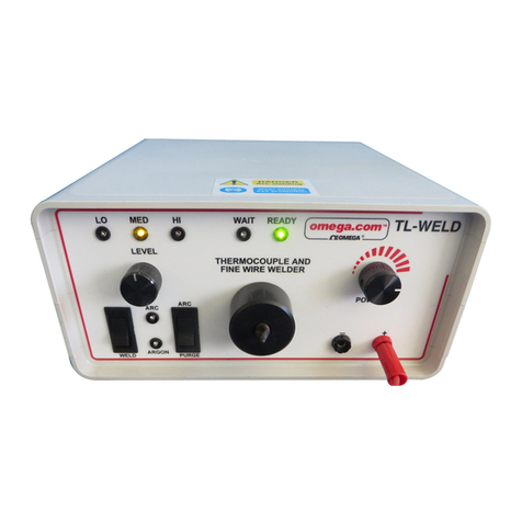
Omega TC-WELD User manual

TC-WELD
Thermocouple & Fine Wire Welder
For latest product manuals:
omega.com/en-us/pdf-manuals
Shop online at
omega.com
User’s Guide

omega.com [email protected]
Servicing North America:
U.S.A. Omega Engineering, Inc.
Headquarters: Toll-Free:1-800-826-6342 (USA& Canada only)
Customer Service: 1-800-622-2378 (USA & Canada only)
Engineering Service: 1-800-872-9436 (USA & Canada only)
Tel: (203) 359-1660 Fax: (203) 359-7700
e-mail: [email protected]
For Other Locations Visit omega.com/worldwide
The information contained in this document is believed to be correct, but OMEGA accepts no liability for any errors
it contains, and reserves the right to alter specications without notice.

3
Product Name:
Model:
Dimension:
Weight:
Weld Wire Diameter:
Duty Cycle:
Input:
Engergy Output:
Power Consumption:
Argon Input Port:
Fine Wire Welder
TC-WELD
220 (W) x 100 (H) x 270 (D) mm
3.6 kg / 7.94lbs
0.08mm / 0.003” to1.1mm / 0.043”
5-10 welds per minute
90-260 VAC / 50-60 Hz
0 to 60 joules
Max 120 VA dropping to 10 VA during charging
6mm (1/4”) Push Connection
Recommended maxinum ow rate 6 liter / minute
General Specification
Accessories
1x Power Cord
1x Foot Switch
1x Bonding Carbon Electrode
1x Bonding Copper Electrode
1x Safety Glasses
1x Spare Fuse
1x Removable Plier with Lead
CE Approval
Directive(s):
Verication No:
Ratings:
Low Voltage Directive (2006/95/EC and 2015/35/EU)
T1507055-507
Input: 100-240Vac, 50-60Hz, 0.5A, Class I
Output: 22-55Vadc, 50W max
The referred CE test report(s) show that the product fullls the essential requirements set out in the Directive(s). On this basis,
together with the manufacturer’s own documented production control, the manufacturer or his European authorized
representative can in his EC Declaration of conformity verify compliance with the Directives(s). The CE marking could be axed
only when all the relevant and eective EC Directives are complied with.

4
Set Up Your Welder
• The welder should be placed on a stable and at working bench for
operation.
• Connect the welder to the power supply with the power cable.
• If using the argon mode, connect the argon hose securely to the argon
inlet at the rear of the welder.
• Adjust argon ow to 6 litres per minute. And check to make sure there is
no leakage.
• Switch on the power button.
• Now the welder is ready to use.
Safety Notes
Thank you for choosing the Fine Wire Welder. This welder is designed
for producing commercial grade thermocouple hot junction. It’s easy
to use and operate. But it is still very important to read the instructions
carefully prior using the welder.
• Always wear protective safety glasses during welding. Do not view
the weld discharge with the naked eye.
• Do not touch directly welding electrode during welding operation.
• Follow the instruction carefully and use the correct power supply.
Always wear protective eyewear during welding!
NOTE
Always Wear
Eye Protection

5
Front Panel Controls
Power On LED
Wait LED
Ready LED
Argon On LED
Black (-) Socket
Red (+) Socket
ON / OFF Switch
Argon Control Switch
Power Setting Selector
Welding Nozzle
A
B
C
D
E
F
G
H
I
J
Indicates power is connected.
Glows when weld charge is building.
Indicates it is ready to weld.
Indicates argon is on.
Output socket connects to the electode. Negative end.
Output socket for using the pliers. Positive end.
To switch the poswer ON and OFF.
ARGON ON allows continuous ow of argon.
LEVEL position is turning the argon o.
PURGE allows short burst of argon gas ow.
Adjusts output power level.
Holds the electrode for welding.
Rear Panel Controls
Argon In
Foot Switch
Fuse
Power In
Connects to the argon hose allowing the welder to weld with argon input.
Connects to the foot switch and able to use the foot switch to control argon ow.
Use a fuse with 2 amps rating only.
Connects to the power cable. Range 90-260 VAC / 50-60 HZ .

6
Welding Instructions
•
Prepare the wires to the Appropriate length and ready for welding.
•
Grip in the pliers, leaving about 1mm or more protruding.
•
Adjust the approapriate power setting according to the wire diameter.
•
Keep steady and position in front of the Electrode.
• If using the argon weld, connect the argon supply to the argon inlet at the back of the welder.
Use the argon switch turn the argon flow on and off.
ARGON ON keeps the argon flow on constantly.
LEVEL position switch off the argon flow.
PURGE is pressed to burst argon flow; release the switch to stop argon flow.
•
Wait for the READY led light turns green, hold the wires using the pliers and then touch the
tip the wires to the Electrode for the welding arc struck.
•
Check the wires welded correctly.
•
If using foot swtich to control the argon ow, connect the foot switch supplied. Press the foot
switch to enable argon ow. Release the foot switch to stop argon ow.
Adjust the power level according to the thermocouple wire diameter. As a reference, we suggest
the following:
•
Unscrew the black weld nozzle cap and put aside.
•
Reveals the electrode holder with the hexegonal socket.
•
Use the supplied hex key to loose the electrode holder.
•
Replace new electrode or adjust the electrode in position. Tilt the welder forward slightly where
necessary to pull out the electrode.
•
Tighten the electrode holder using the hex key.
•
Screw the welding nozzle cap in place securely.
•
If there is uneven working surface on the electrode, you may use sand paper or equivalent tools
to smooth the working surface of the electrode.
Replace or Adjust Elctroctode
Switch power o before you replace or adjust the Electrode!
NOTE
Wire Diameter
Power Output Level
Electrode
20AWG (0.80mm)
16-17
Carbon
28AWG (0.32mm)
5-6
Carbon
30AWG (0.25mm)
5-6
Carbon
36AWG (0.13mm)
5-6
Copper
40AWG (0.08mm)
4-5
Copper

WARRANTY / DISCLAIMER
RETURN REQUESTS / INQUIRIES
1. Purchase Order number under which
the product was PURCHASED,
2. Model and serial number of the product
under warranty, and
3. Repair instructions and/or specic
problems relative to the product.
1.
Purchase Order number to cover the
COST of the repair,
2. Model and serial number of the product, and
3. Repair instructions and/or specic problems
relative to the product.
OMEGA ENGINEERING, INC. warrants this unit to be free of defects in materials and workmanship for a period of
__ months from date of purchase. OMEGA’s WARRANTY adds an additional one (1) grace period to the normal __ year
product warranty to cover handling and shipping time. This ensures that OMEGA’s customers receivee
maximum coverage on each products.
If the unit malfunctions, it must be returned to the factory for evaluation. OMEGA’s Customer Service Department will
issue an Authorized Return (AR) number immediately upon phone or written request. Upon examination by OMEGA,
if the unit is found to be defective, it will be repaired or replaced at no charge. OMEGA’s WARRANTY does not apply
to defects resulting from any action of the purchaser, including but not limited to mishandling, improper interfacing,
operation outside of design limits, improper repair, or unauthorized modication. This WARRANTY is VOID if the unit
shows evidence of having been tampered with or shows evidence of having been damaged as a result of excessive
corrosion; or current, heat, moisture or vibration; improper specication; misapplication; misuse or other operating
conditions outside of OMEGA’s control. Components in which wear is not warranted, include but are not limited to
contact points, fuses, and triacs.
OMEGA is pleased to oer suggestions on the use of its various products. However, OMEGA neither assumes respon-
sibility for any omissions or errors nor assumes liability for any damages that result from the use of its products in
accordance with information provided by OMEGA, either verbal or written. OMEGA warrants only that the parts
manufactured by the company will be as specied and free of defects. OMEGA MAKES NO OTHER WARRANTIES OR
REPRESENTATIONS OF ANY KIND WHATSOEVER, EXPRESSED OR IMPLIED, EXCEPT THAT OF TITLE, AND ALL IMPLIED
WARRANTIES INCLUDING ANY WARRANTY OF MERCHANTABILITY AND FITNESS FOR A PARTICULAR PURPOSE ARE
HEREBY DISCLAIMED. LIMITATION OF LIABILITY: The remedies of purchaser set forth herein are exclusive, and the
total liability of OMEGA with respect to this order, whether based on contract, warranty, negligence, indemnication,
strict liability or otherwise, shall not exceed the purchase price of the component upon which liability is based. In no
event shall OMEGA be liable for consequential, incidental or special damages.
CONDITIONS: Equipment sold by OMEGA is not intended to be used, nor shall it be used: (1) as a“Basic Component”
under 10 CFR 21 (NRC), used in or with any nuclear installation or activity; or (2) in medical applications or used on
humans. Should any Product(s) be used in or with any nuclear installation or activity, medical application, used on
humans, or misused in any way, OMEGA assumes no responsibility as set forth in our basic WARRANTY/DISCLAIMER
language, and, additionally, purchaser will indemnify OMEGA and hold OMEGA harmless from any liability or
damage whatsoever arising out of the use of the Product(s) in such a manner.
Direct all warranty and repair requests/inquiries to the OMEGA Customer Service Department. BEFORE RETURNING
ANY PRODUCT(S) TO OMEGA, PURCHASER MUST OBTAIN AN AUTHORIZED RETURN (AR) NUMBER FROM OMEGA’S
CUSTOMER SERVICE DEPARTMENT (IN ORDER TO AVOID PROCESSING DELAYS). The assigned AR number should
then be marked on the outside of the return package and on any correspondence.
The purchaser is responsible for shipping charges, freight, insurance and proper packaging to prevent breakage in
transit.
FOR WARRANTY RETURNS, please have the
following information available BEFORE
contacting OMEGA:
FOR NON-WARRANTY REPAIRS, consult OMEGA for
current repair charges. Have the following information
available BEFORE contacting OMEGA:
OMEGA’s policy is to make running changes, not model changes, whenever an improvement is possible. This aords our customers
the latest in technology and engineering.
OMEGA is a trademark of OMEGA ENGINEERING, INC.
© Copyright 2019 OMEGA ENGINEERING, INC. All rights reserved. This document may not be copied, photocopied, reproduced,
translated, or reduced to any electronic medium or machine-readable form, in whole or in part, without the prior written consent
of OMEGA ENGINEERING, INC.

TEMPERATURE
Thermocouple, RTD & Thermistor Probes, Connectors, Panels & Assemblies
Wire: Thermocouple, RTD & Thermistor
Calibrators & Ice Point References
Recorders, Controllers & Process Monitors
Infrared Pyrometers
PRESSURE, STRAIN AND FORCE
Transducers & Strain Gages
Load Cells & Pressure Gages
Displacement Transducers
Instrumentation & Accessories
FLOW/LEVEL
Rotameters, Gas Mass Flowmeters & Flow Computers
Air Velocity Indicators
Turbine/Paddlewheel Systems
Totalizers & Batch Controllers
pH/CONDUCTIVITY
pH Electrodes, Testers & Accessories
Benchtop/Laboratory Meters
Controllers, Calibrators, Simulators & Pumps
Industrial pH & Conductivity Equipment
DATA ACQUISITION
Communications-Based Acquisition Systems
Data Logging Systems
Wireless Sensors, Transmitters, & Receivers
Signal Conditioners
Data Acquisition Software
HEATERS
Heating Cable
Cartridge & Strip Heaters
Immersion & Band Heaters
Flexible Heaters
Laboratory Heaters
ENVIRONMENTAL
MONITORING AND CONTROL
Metering & Control Instrumentation
Refractometers
Pumps & Tubing
Air, Soil & Water Monitors
Industrial Water & Wastewater Treatment
pH, Conductivity & Dissolved Oxygen Instruments
M0000/0000
Where Do I find Everything I need for
Process Measurement and Control?
OMEGA... Of Course!
Shop online at omega.com
Table of contents
Other Omega Welding System manuals
Popular Welding System manuals by other brands

ESAB
ESAB Origo Mig 3001i instruction manual

Elektra Beckum
Elektra Beckum mig mag 232 ep operating instructions

Astro Pneumatic Tool
Astro Pneumatic Tool COMBI120 quick start guide

Miller
Miller Millermatic 35 owner's manual

Everlast
Everlast Powertig 250EX Operator's manual

Hobart
Hobart STICKMATE LX owner's manual