OMP 60" Sbach 342 User manual

60” Sbach 342
Electric Aerobatic Aircraft

Specifications:
Wing Span: 60 inches
Length: 58 inches
Power: Hacker A50-14S
(or equivalent)
Battery: 3800 5-cell LiPo
ESC: 60-70 amp
Flying Weight: 4.75 - 5.25 lbs
OHIO MODEL PRODUCTS
199 Stratford Lane
Xenia, Ohio 45385
(937) 372-0603
www.ohiomodelplanes.com
email: [email protected]
All contents copyright 2012, Ohio Model Products
Version 2.0, January 2013
Dear OMP Customer,
Thank you for purchasing the new OMP/EG electric aerobatic aircraft. This manual covers the SBACH
342 electric aircraft. Ohio Model Products is known worldwide for the best profile aircraft designs around
and many innovative construction techniques. We’ve taken this expertise and teamed up with EG Aircraft
to bring this new model to the radio control enthusiasts. The new 60" Electric Sbach 342 is a state
of the art all out 3D machine for the most ardent 3D flyers. With a Hacker A50-14S or
equivalent motor and a 5 Cell Lipo and supplied side force generators, the Sbach can do
any 3D maneuver you can think of plus some. With a Hacker A40 or equivalent motor and
4 cell Lipo this plane is a gentle sport flyer for a lazy afternoon of flying. The OMP Sbach
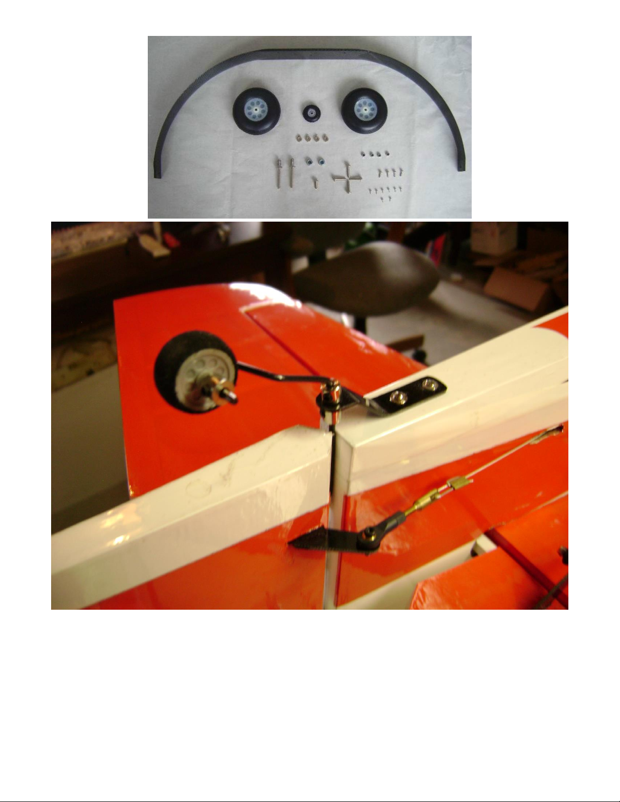
comes with carbon fiber main and tail wheel landing gear assemblies, wing tube, battery
tray and painted CF spinner. The plane is also covered in Ultracote in three different color
schemes.
Sincerely,
John Drake and Bradley Petty
A QUICK WORD ABOUT SAFETY AND RADIO CONTROL FLYING MODELS
With radio control aircraft, like any hobby or sport, there are certain risks. The operator of these
models is responsible for these risks. If misused or abused, you may cause serious bodily injury and/or
damage to property. With this in mind, you will want to be certain that you build your model carefully
and correctly. If you are not an experienced flier, have your work checked and ask for help in learning to
fly safely. This model aircraft is not a toy and must be operated and flown in a safe manner at all
times. Always perform a pre-flight check of the model including all control surfaces, proper function of
the radio gear, structure, radio range, and any other area relating to the safe operation of this aircraft.

Models are not insurable but operators are. You can obtain coverage through membership in the
Academy of Model Aeronautics (AMA). For an AMA information package call 1-800-435-9262, ext.
292 or visit the AMA website at "www.modelaircraft.org".
By the act of using the final assembled model, the purchaser/operator accepts
all resulting liability.
OHIO MODEL PRODUCTS WARRANTY AND RETURN POLICY
Ohio Model Planes guarantees this product to be free from defects in both material and
workmanship at the date of purchase. This does not cover any parts damaged by use, misuse or
modification. In no case shall OMP's liability exceed the original cost of this kit. Because OMP has no
control over the final assembly or equipment/components used in the final assembly, no liability shall be
assumed for any damage resulting from the use of this model by the user. By the act of using the final
assembled model, the user accepts all resulting liability. If you should find any missing or damaged
parts, or have any questions about this product, please contact OMP within 30 days of the purchase in
OMP at (937) 372-0603. If you wish to return this product you must first contact OMP and a 15%
restocking fee will be assessed. Only unused products may be returned. The customer is responsible for
all return shipping charges both ways and any damage as a result of misuse or shipping.

Check out these Features:
Carbon Fiber Wing Tube
Carbon Fiber Main Landing Gear
Carbon Fiber Tail Wheel Assembly
Carbon Fiber Reinforced Fuselage
Carbon Fiber Battery Tray
Side Force Generators
Matching painted Carbon Fiber
Spinner
Advanced Ball Links and Pushrods
Extra Ultracote Covering for Repairs
Complete Hardware Package
Note: As with all kits, it’s a good idea to read all the instructions and study the parts
before you begin construction. Handle the parts of this kit with care so you do not
damage any of the structure or covering. Inspect all the parts for any shipping
damage and report any issues to OMP as soon as you can. Make sure you have a flat
and sturdy workbench and follow all safety advice for the tools and adhesives you
plan to use.

AIRCRAFT COVERING:
1. With all ARFs, varying temperatures and storage delays can cause covering material to loosen over
time and transportation. OMP recommends lightly going over all the covering with a covering iron
set at medium temperatures. Be sure to use a soft cover over your iron so you do not scratch the
covering surface. Be sure you go over all seams and edges of the covering to assure it is secure to the
airframe and other covering. Be careful not to apply too much heat or you may cause bubbles or
damage to the covering. A heat gun may also be used along with a soft cotton cloth to shrink and
adhere the covering. Again, be extremely careful when using a heat gun.
2. Some modelers prefer to seal the hinge gaps using strips of appropriate covering or clear trim tape.
We have found this to be helpful with models intended for higher speed flight or models with
unusually large hinge gaps. OMP aircraft utilize a very tight double beveled hinge line and do not
normally require this step. Sealing the hinge gaps is therefore left as an option for the modeler.
RUDDER INSTALLATION:
1. It is much easier to install the control horn before installing the rudder. Locate the carbon fiber rudder
control horn, ball links, and associated bolts and nylon-insert lock nuts. Use some fine sandpaper to
roughen up the center area of the control horn so that the glue adheres better. Using a sharp hobby knife
cut the covering away from the slots in the rudder and trial fit the control horn.
2. Mix up some 30 minute epoxy and coat the inside of the slot and the center of the control horn. Hint:
a scrap piece of 1/16” ply, tooth pick, or old hobby blade can be used to coat the inside of the rudder slot.
Slide the control horn in place and make sure it is centered perfectly by using a ruler to measure between
the pivot holes and the hinge line. Wipe any excess glue off with isopropyl alcohol and paper towels.
Set aside until cured.

3. The hinge slots for the rudder are pre-cut in the rudder and fin. Locate the CA hinges and align them in
the fin. Once aligned and centered in the fin glue in place with thin CA.
LANDING GEAR ASSEMBLY:
1. Locate the supplied main and tail wheel landing gear parts and sort them out on your workbench.

2. Bolt the main gear to the bottom of the fuselage using the supplied bolts. Use a small drop of thread-
lock to secure the bolts in place.

3. Install the main wheel axles to the composite landing gear and tighten the nylon-insert lock nut. Note
that the axle is a hex head bolt. The hex head part of the bolt is to the outside of the wheel. Use 1-2 nuts to
space the wheel from the axle for wheel pant fit. Insert axle and wheel in main landing gear and use a
nylon locking nut to secure axle and wheel to main gear. See picture below for clarity.

4. Fit the wheel pant in place and install using the two supplied wood screws. Repeat the above steps for
the other main gear.
5. Begin the tail wheel assembly by installing the shaft through the hole at the rear of the tail wheel
bracket. Note there is a wheel collar above and below the tail wheel bracket hole. Install the tail wheel
using two supplied wheel collars. Again, the use of thread-lock on any metal to metal screw is advised.

6. Center the tail wheel bracket on the rear of the fuselage. Note that the steering arm attaches into the
rudder and the steering arm shaft has to fit flush against the fin. Before attaching tail wheel assembly,
make a 90 degree bend in the last 1” of the shaft. Make sure that you make the bend in the right direction!
The bent part has to fit into the rudder to provide rudder steering on the ground. Screw the tail wheel
assembly in place using the two supplied wood screws. Remove the screws and harden the holes with a
drop of thin CA. Allow the CA to cure and then permanently install the tail wheel bracket. Don’t install
the rudder at this time.
RUDDER CONTROL INSTALLATION:
1. The SBACH 342 is supplied with a set of pull-pull cables and ball-links for mounting the rudder servo
on the radio trey. There are also servo mounts in the tail to mount the rudder servo. Depending on what
type of motor and battery size you install on the plane, you might want to mount the rudder servo in the
tail to help with plane balance. If you put the rudder servo in the tail, you can use the ball links however,
you will have to make your own rod for the rudder servo as this is not supplied. If you use a Hacker A50
series motor or equivalent and 5 or 6 cell Lipo, then mount the rudder servo in the tail. If you use an A40
series motor or equivalent motor and 4 cell Lipo, then mount the rudder servo on the radio trey. NOTE:
Due to the large amount of motors and batteries that can be used with the plane, I would make the
decision on where to mount the rudder servo until after the plane is finished and you have done some
preliminary CG checks.

2. Now install the rudder to the fuselage. Slip the CA hinges into the precut slots and make sure the
rudder is aligned correctly and glue the hinges with thin CA. Next, install your rudder servo into the
precut locations in either the radio trey or fuselage side in the tail (See note above). You will need to
locate the hole in the side of the fuselage and remove the covering. The hole is just below the leading
edge of the horizontal stabilizer. You can mount the supplied full rudder servo arm to your circular servo
wheel that comes with what every servo that you are using. Use the full arm for the radio trey mounted
servo and cut one side off for the tail mounted servo. Set up your radio accordingly and center the rudder
servo. The geometry of your servo arm relative to the rudder horn is critical for proper rudder operation
without binding or excess cable slack.
3. Locate the pull-pull cable set, threaded couplers, brass swaging tubes, and ball-links. If the cable is
one long piece, cut it into two equal length pieces. Thread one end of the cable through a brass tube and
then through one of the threaded couplers. Run the cable back through the brass tube and then loop it
back through a second time. Using a set of crimping pliers, place three crimps just tight enough not to cut
the brass tube but enough to securely hold the wire in place. Cut off the excess cable with wire cutters.
Wick thin CA into the brass tube to help hold the cable secure. Repeat for the other cable.
4. Thread the couplers about half way into the ball links of the rudder. Hint: remove the ball links from
the rudder horn first to make this step easier and then re-install once the couplers are threaded on. Feed
the loose end of each cable into the cable slots at the rear of the fuselage and feed them forward towards
the servo mount location. A coat hanger with a hook on the end can be useful here if you can’t reach the
cable.

5. Use your radio system to center the rudder servo and attach either the supplied arm or an appropriate
arm for your servo. Thread one of the ball links about half way onto one of the threaded couplers. Feed
the loose end of one of the cables through a brass tube and then through the threaded coupler. Holding
the rudder centered, adjust the cable length as tight as possible while checking the ball link position over
the servo arm. When satisfied with the position, pinch the cable around the threaded coupler and then
feed the loose end back through the brass tube. Loop the cable back through the brass tube as before and
crimp the brass tube three times just tight enough not to cut the brass tube but enough to securely hold the
wire in place. Cut off the excess cable with wire cutters. Wick thin CA into the brass tube to help hold
the cable secure. Repeat for the other cable. Hint: Once you have established the position of the
threaded coupler on the cable, you can remove the ball link from the rudder horn to give you more
working slack in the fuselage. Re-install the ball link prior to setting the other cable.
6. Check the operation of the rudder using your radio and make sure there is no binding and the cables
are adjusted properly. You may have to tighten the cables after a few flights as they may stretch slightly
from the initial installation.
ENGINE INSTALLATION:
1. Depending on which motor you choice to use, you may need to make some engine stand offs to get the
required cowl clearance. If you use the Hacker A50-14S or equivalent you will need about 3/16 spacers. If
you use the Dualsky motor that OMP sells in the combo package, you will need to make 5/8”stand offs.
Notice that the engine center line needs to be offset to the left to compensate for the right thrust built into
the engine box.
2. Place the cowling in place on the fuselage and measure the distance from the firewall to about 1/8” in
front of the cowling. This figure represents the back of the spinner and will help you determine if you
need to space your engine out from the firewall using washers or additional wood dowel offsets. Mount
your engine securely using bolts, washers, and locknuts. The use of thread-lock is also highly
recommended for the engine bolts.

.
COWLING INSTALLATION:
1. Locate the four screws that are put into the blind nuts that are installed in the fuselage. These four
screws are the mounting device for the cowling. The holes that are in the cowl ring may need to be
enlarged slightly to allow the heads of the screws to slide through them. Once the four screw heads have
been aligned into the cowl ring, gently push the cowling down to it fits in place and is aligned with the
fuselage.
2. Install the propeller and spinner. Follow the manufacturer’s instructions and make sure your props are
well balanced, properly drilled, and display no cracks or chips. NOTE: If you have purchased the Daulsky
motor, you will need to get a 3mmX50mm bolt to mount the spinner.
HORIZONTAL STABILIZER AND ELEVATOR CONTROLS ASSEMBLY:
1. Locate the horizontal stabilizer and trial fit into the fuselage opening. Temporarily install the wings and
center the stab on the fuselage. Make sure the stab is level with the wings. Now make sure the stab is even
for and aft with respect to the wings by measuring from the wing trailing edge at the tip to the leading
edge of the stab at the tip. Make sure both sides are the same. You may have to trim the fuselage some to
get a straight fit of the stab. Take out the stab from fuselage and remove the covering in the middle of the
stab on both top and bottom. Be careful not to remove too much covering. Glue the stab in place using 30

minute epoxy. The slow drying time will give you the time to make the alignment measurements again
and get the stab on straight.
2. Locate the elevator halves, elevator connecter piece and CA hinges. Starting with the elevator half that
will be on the elevator servo side, locate the control horn opening and remove covering and glue in carbon
fiber servo horn with CA. Now trail fit the CA hinges into the slots in the elevator half and stab. Center
the CA hinges and glue into the elevator half. Remove some of the covering on the elevator connector
piece to get a good glue joint and glue in place. Trail fit the CA hinges into the stab and position the
elevator half, don’t glue hinges into stab just yet. Glue CA hinges into remaining elevator half . Trail fit
the CA hinges into the stab and align the elevators to the stab. Once satisfied with the fit, glue hinges into
the stab with thin CA. Also, glue the other elevator half into the connector piece. This completes the
installation of the stab and elevators. NOTE: Some flyers may choice to put two elevator servos in the
tail, one on each elevator side. If you choice this method, then mount the rudder servo under the canopy.
3. Use your radio to set the servo center position and install the control horn onto the servo. Assemble
the control rod and ball links and adjust the control linkage for proper geometry. When satisfied, screw
the ball link to the servo horn in the elevator and servo arm on servo. The servo arm should be as close to
perpendicular to the control rod as possible while the elevator is at neutral. Double check all screws, bolts
and nuts to assure proper installation and operation without binding.
WING AND AILERON CONTROLS ASSEMBLY:
1. Locate both wing panels and ailerons and CA hinges. Trail fit the CA hinges into the aileron and wing
and put together for fit. Once satisfied, remove aileron and center and glue the CA hinges with thin CA
into the aileron. Once the hinges are dry, then glue aileron to wing. Repeat with other wing panel. If you
want to use the supplied Side Force Generators, then locate the slots on the top and bottom of the wing tip
and remove covering. Locate the two holes in the wing tip and remove covering.
2. Locate and cut the covering from the aileron servo horn opening slots. from corner to corner and iron
down inside the openings. Feed the servo wires into the wing and out the root. Install the servos and
screw firmly in place.
3. Use your radio to set the centers of each servo and then assemble and adjust the length of each control
rod. The servo arm should be as close to perpendicular to the control rod as possible while the aileron is
at neutral. Double check all screws, bolts and nuts to assure proper installation and operation without
binding.
7. Check the final radio operation of the ailerons and make sure there is no binding or servo fighting of
each other. Also check to make sure all linkage bolts and nuts are secure.
FINAL RADIO SYSTEM INSTALLATION:
1. Whether you use 72 MHz systems or the 2.4 GHz systems, proper radio installation and care is vital to
the safe and reliable operation of your aircraft. Follow the manufacturer’s instruction for installation
guidance of receiver and battery paying attention to factors such as adequate cooling, and clearances.

2. Mount your reciever securely in a location which provides a clean and maintenance free solution to
your setup. All servo wires should be neatly routed and secured in place so they will not come loose or
flop around during flight.
3. The fuselage ply sides provide space to mount your switches just below the canopy. Mount your
switches according to the manufacturer’s instructions and route your wires safely and securely as above.
4. Your receiver battery(s) can be mounted in a variety of locations depending on your balance needs.
Regardless of where you mount your batteries it is vital that they are very secure with no possibility of
coming loose. Use double sided velcro to hold the batteries from sliding around and then use zip ties or
velcro straps to secure them tightly in place.
5. Servo and battery leads are the life blood of your aircraft. Make sure all wires are top quality and
connectors are tight and display no loose pins or frayed wires. Servo clips are provided in the kit for your
convenience. These servo clips can even be glued to the wood structure using CA if desired.
6. Check all radio programming and control surface operations thoroughly before your initial flight.
Check your radio range according to the radio manufacturer’s instructions both with the engine off and
running.
BALANCING and PRE-FLIGHT:
1. Most state of the art aerobatic aircraft allow for a wide margin for balancing depending on what level
of precision or freestyle the pilot prefers. To perform properly without being too pitch sensitive, you must
not go too aft on the CG. OMP recommends the initial CG setting of the leading edge of the wing
tube. Once you have flown the plane several times, then move the battery back and forth to achieve
the CG that best suits you flying style. More experienced pilots may want to set the CG further aft for
more 3D capability. Varying weights of engines and radio gear will dictate how you should install each.
Servo cutouts are provided in the rear of the fuselage for the rudder servo if needed to help with balance
of the plane. These options should allow you to balance the model without adding any weight.
Note: The best way to check your balance is to trim for level flight at about 1/2 to 3/4 throttle and then
roll inverted. The aircraft should maintain level flight with very little to no down elevator input. If the
aircraft climbs when inverted then you’ve probably got your CG too far aft. If the nose drops more than
slightly, then you are most likely nose heavy.
Recommended control surface deflections:
Low Rate
High Rate
Elevator
12 degrees
45-50 degrees
Rudder
25 degrees
40 - 45 degrees
Ailerons
20 degrees
35-40 degrees
FINAL ASSEMBLY AND PRE-FLIGHT INSPECTIONS:
1. Before arriving at your flying field, be sure all your battery is properly charged and all radio systems
are in proper working order.
2. Install the wings onto the fuselage being careful to align the wing tube with the wings and not force it.
The wing tube may be initially tight but will loosen some with use. Guide your servo wires into the

fuselage openings and connect to the proper aileron channels. Servo clips are recommended. Once you
have the wings fully seated in the fuselage tighten the wing bolts inside the fuselage.
3. Position the canopy in place and check it is tight.
4. Check all control surfaces for secure hinges by performing a slight tug on the control surfaces and
observing if there is any give in the hinges. Check all control rods, ball links, servo screws, etc. for
proper operation and installation.
5. Check your batteries and perform a proper range check once again with the engine off and running. Be
sure all surfaces are moving in the correct direction and the proper amount for your flying setup.
6. You are now ready for your maiden flight! Good luck and enjoy your new aircraft! If you have any
comments or questions about this manual or the aircraft please email “[email protected]”.
OHIO MODEL PRODUCTS
199 Stratford Lane
Xenia, Ohio 45385
(937) 372-0603
www.ohiomodelplanes.com
Table of contents
Other OMP Toy manuals
Popular Toy manuals by other brands

VQ Model
VQ Model A26K COUNTER INVADER Assembly instructions

Lionel
Lionel Hot Metal Car owner's manual

marklin
marklin mini-club BR 50 manual

Mountain Models
Mountain Models P-51 Mustang Assembly manual

Carf-Models
Carf-Models Extra 330sc Assembly manual

Eduard
Eduard BRASSIN MiG-21 wheels 1/48 quick start guide