Maintenance
4
dpc
%n
hs
500
stnd
500 4000
shs
50
dpc
%ff
----
9999
MODE
MODE
MODE
2.
DetectionFunction ChangingLight Leveland Response Time
per
%ff
per
%n
3. DPCFunction StableDetection Regardlessof Incident (Two outputs aredisplayed)
LightLevel Change
4.Timer Function Setting OutputTimer (Two outputs are displayed)
UP/DOWN
UP/DOWN
13.InvertedDisplay *2
MountingAmplier in Inverted Direction
12.Digital Display *2
ChangingDigital Display in RUN Modefor SpecicPurpose
6.BANKSwitching Setvaluesare saved foreach conguredbank.
8.PercentageTuning
DetectingTransparentor Microscopicobject
(Twooutputs are displayed)
MODE
MODE
MODE
MODE
MODE
%ff
B
UP/DOWN
UP/DOWN
UP/DOWN
UP/DOWN
(IncidentLightLevelExample)
Detailed Settings
5
dflt
MODE
1.Function Selection Enabling 6to 16
ec%
%ff
ec%
%n
UP/DOWN
husr
37
37
UP/DOWN
14.EcoFunction *2 Saving PowerConsumption
MovetoDetectionModebyholdingthebuttonfor3secondsorlonger.
15.Hysteresiswidth
5. PowerTuning Level Changing theTarget Incident Light Level (PowerTuning Level)
%n-d
10 10 ----
std
A
A
UP/DOWN
UP/DOWN
2 3 4
Select [Setting Mode] -> [Digital Display] to set [diSP CFdr].
Pressing the [MODE] button for 3 seconds or longer exits the SET mode.
Before Passing Right after passing
Let the workpiece pass.
1.
2.
3.
0
2000
Holdbothfor3sec.or longer Hold both for 3sec.orlonger
6000
4000
20009999 2000 1000
Enable Cancel
Convenient Setting Features
3
For Stable Detection Regardless of Received Light Intensity Changed due to Dust or Dirt
●Zero Reset Function
Returning Received Light Intensity Display to "0"
●Change finder
Checking Received Light Intensity When Workpiece Passes at High Speed
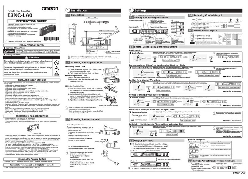
E3NX-MA□□Series
Thethresholdalsochangesaccordingly.
The lower threshold limit is -1999.
hstd
STND Standard Mode
(a)O-delay Timer
Time O
(b)On-delay Timer (c)One shot (d)On O-delay Timer
DPC ON
SHS Super High-speed ModeGIGA Giga Power Mode
HS
High-speed
Mode
DPC OFF
%n
ptun
MODE
7.PowerTuning ON/OFF Setting ToTurn ON/OFFthe LightAmount
Adjustmentat Tuning
UP/DOWN
Powertuning
adjustmentON
PercentagetuningON
Percentage
tuningOFF
std
9.Output1 Mode Outputmode for theoutput 1is changed.
UP/DOWN
Normal
detectionmode
Basicsetting
Detailedsetting
Threshold
/Receiving
light amount
Normal Reverse
Ecofunction
OFF
EcofunctionON
EcofunctionLO
Standard
setting
Usersetting
fd
f
MODE
BANK1
BANK2 BANK3 BANK4
ban
B
MODE
T
T
T
T
O-delay Timer
Holds the output ON for
detection by PLC when
the detection time is too
short.
On-delay Timer
Delays the output ON
after detection.
No Incident Light
Incident Light No Incident Light
Incident Light
No Incident Light
Incident Light
No Incident Light
Incident Light
ON
OFF
ON
OFF
L-ON
D-ON
ON
OFF
ON
OFF
L-ON
D-ON
Tb
Ta
Tb
ON
OFF
ON
OFF
L-ON
D-ON
Ta
(a)
(b)
One-shot Timer
Keeps the output ON for
a specied time regardless
of the workpiece size
variations.
T
T
ON
OFF
ON
OFF
L-ON
D-ON
(c)
ON/OFF-delay Timer
Sets both OFF-delay Timer
and On-delay Timer.
(d)
ban ban ban
Thedisplay reverses.
Thresholdand light intensity are displayedon
greendigital and white digital respectively.
The OUT Selection Indicators show items
for Output1/Output 2 individually for each output.
The DPC indicator turns ON
when the DPC function is
effective.
●DPC Function
Time
内部受光量
Internal Incident Light Level
Incident Light
Level
Displayed Incident Light Level
Threshold
Level
Stabilizes the displayed
incident level by
correcting internal
incident level changes.
Smart
Tuning SET
mode
Run Select
DPC Function
ON
Ratings and Specifications
4-2
Hold button for 3 seconds or longer to enter SET mode.
MODE
SET mode provides the following function settings. The initial display
shown after transition from one function to another represents the
factory default.
UP/DOWN
Use button to set the power tuning level.
(100 to 9999 in 1 steps; the initial value: 9999)
UP/DOWN
Use button to set the time.
FunctionSelection: [ ]
FunctionSelection: [ ]
Press button in [ ] menu, then use
button to set the percentage tuning level.
(-99% to 99% in 1% steps; the initial value: -6%)
MODE
UP/DOWN
func
func
Detectionfunction
Responsetime
Lightquantity
HS
450μs 1ms 16ms 100μs
1(reference)
STND
x1
GIGA
x8
SHS
x0.1
Besuretocheckthestabilityofoutputs
asthereisapossibilityofchattering.
Thehysteresiswidthcanbesetbypressingthebuttoninthemenu
of"husr"andthenpressingthebutton.(0to9999,incrementsof1)
MODE
UP/DOWN
UseoftheDPCfunctionwiththrough-beammodel
orregressivereflectionmodelisrecommended.
MODE
After pressing the button,
(Referencevalue)
ec%
l%
Ecoon
Theindicators (green digital and whitedigital) turnOFF.
Theyturn ON for approx. 10seconds andthen turn OFF
bybutton operation.
EcoLo
Theyturn ON for approx. 10seconds andthen
theindicators (All) turn ON
withlow brightness.
h
Thechangefinderisnot
displayedin[SettingMode].
Iftheproductisthereflective
type,thelocalmaximumvalueis
displayedbysettinglight-on.Ifit
isthethrough-beamtype,the
localminimumvalueisdisplayed
bysettingdark-on.
ptun
%ff
PowertuningadjustmentOFF
area
Areadetectionmode*1
(Twooutputs are displayed)
Setthe hysteresis width by initialvalue. Hysteresiswidth is provided for
thresholdto prevent the judgment outputfrom becomingunstable
nearthe boundaries.
(1 to 9999ms in 1ms steps; the initial value: 10ms
Errorrange
:
0.1ms
)
●
Troubleshooting
Problem Cause Remedy
Remedy
Cause
ErrorName / Display
●
Error Display
2000
4000
Troubleshooting
4-1
DPC Error*1
TurnONthepoweragain.Reset the settings if
theerrorisnotcorrected.*3
Iftheerrorremains,theerror is caused by
memoryfailuresuchasrewritecount exceeded.
Pleasereplacetheamplierunit.*5
Load short circuit detection error
Lock ON
*2 Refer to "⑤Detailed Settings".
Cancelthekey lock function.*3
Checkwiringand connector connection again.
*4
Failedinternaldata
read/out
Thekeylock function
enabled
Overcurrentowing
tothecontrol output
*4 Refer to "③Convenient Setting Features"
*1Refer to "1-2 Input/Output Circuit Diagram"
*3Refer to "1-3 Mounting Amplier Unit"
*2Refer to "2-5 Smart Tuning "
*4Refer to "1-2 Input/Output Circuit Diagram"
and "4-2 Ratings and Specications"
*1The DPC indicator blinks.
*3Refer to "③Convenient Setting Features"
e-st
Checkthe wiring, connectorconnection,powersupply
voltageand power supplycapacityagain.*1
Nothingisshown
ontheindication. No power supplied or the
cablebroken
TurnOFF Eco mode.*2
Nothingisshown on the
digitalindication.
Ecomodeis ON.
ChecktheAmplier Units mounted in a group and
turnONthe power again.
*3
TheOUTindicator
blinking Mutualinterferenceor
otherreason
Cancelthezero reset function. *4
Incidentlightlevel displayed
inanegative value
Thezeroreset function is
enabled.
Thelightintensity level
displaychanges.
Aectedbydust or dirt, temperature
change,vibration,etc.
Resetthesettings.*4
Losttrackingof
thesettingsmade ー
SettingGIGA Mode increasesemissionpower
andlight intensity.*2
Sensing/Detection
notpossibledespite
theminimum
thresholdlevel
Detectionsetto a small
lightlevelmode Dust or dirt
inuences
Wipethedust o the Fiber Unit detection
surfaceorother relevant areas and recover the
originalincidentlight level. Then, perform
SmartTuning.*2
Theincidentlight level
hasdeteriorateddue to
dustordirt.
EEPROM error
(Two outputs are displayed)
(Two outputs are displayed)
150p
(a)
2000
8000
(b) (c)
3000
3500
(d)
3000
(e)
9999
2000
(f)
Threshold
Received light intensity ratio Peak receiving light amount
Bottom receiving light amount
Threshold
120% 100% 80%
Peak receiving light amount
Receiving light amount
CH number
Receiving light amount
Threshold
Received light amount after passing
3000
2000
(g)
OUT1 receiving light amount OUT2 receiving light amount
p-b bar
(a)Toseethereserveofthelight
intensitylevelforthethreshold
(b)Tosetthethresholdwitha
microscopicobjectorfast-movingobject
(c)Toseetheintuitiveand
easytofollowdisplay
(d)Toadjustthebeam
per
(f)Toseethereceivedlightintensity
whenworkpiecepassesathighspeed
cfdr
(e)ToknowtheCHnumberwhentwo
ormoreunitsconnected
ch
(g)Toseethereceivedlightintensityof
OUT1andOUT2simultaneously
dgdg
Press both the [MODE] and [L/D] buttons for at least 3 seconds
to set to [SoLU on]. To release the setting, press the [MODE]
and [L/D] buttons for at least 3 seconds to set to [SoLU oFF].
Let the workpiece pass.
Passing time and light amount difference are displayed.
1.
2.
3.
LightamountdifferencePassingtime
(m:msec,μ:μsec) LightamountdifferencePassingtime
(m:msec,μ:μsec)
0m
0
500m
63
Enable/Cancel
(The same procedure)
rst
●Solution Viewer
Determining If Workpiece is Detectable
●Setting Reset
Initializing Settings
rst
●Key Lock Function
Preventing Malfunction
●User Save Function/User Reset Function
Saving/Reading Settings
Initialize all settings to the factory-set defaults.
Disables all the button operations.
* Press either of UP/DOWN.
Holdbothfor3sec.or longer
Holdbothfor3sec.or longer
Holdbothfor3sec.or longer
Lightamountdifference
Threshold
Passingtime
(msorμs)
[rst]
MODE MODE
[]
UP/DOWN
[rst][rst user]
yes
MODE MODE
UP/DOWN
[] [ ]
UP/DOWN
UP/DOWN
MODE MODE
User Save Function
User Reset Function
e-me *
MODE
A
When executing the DPC function or smart
tuning, zero resetting is cancelled.
"Enable/disable" of zero resetting and the
zero resetting value can be saved for each
bank.
User Resetting and User Saving are applicable to the bank common
setting only.
Thereceivinglight intensity display is
stabilizedusingthe DPC function.*4
Theasterisk*representsanumber.
Whilewriting in theEEPROM, setting initializationand
userresetting are disabled.Wait for acouple of seconds
andtry again.
Settingchangeor
writingtothe
EEPROMaredisabled.
Settingchangeexecutionerror
*isinitorUSEr
err
*
*1. The relationship between the control output and output switch during area detection mode is as follows:
Hi
Lo
ON
OFF
ON
OFF
Light ON
Control output
Light ON
Control output
*2. It is a common setting for BANK. Only one set value can be set between BANK1 to BANK4.
*3. Be sure to set the timer function to One-shot mode when selecting“Falling synchronization mode”or
“Rising synchronization mode”.
%n
UP/DOWN
16.Writing to EEPROM *2
ON
OFF
TurningON/OFF of thesetting change saveby batch tuning
If the setting is [OFF], the change of the setting including tuning and
setting initialization via the communication command is not saved,
preventing the rewrite count (1 million times) exceeded.
MODE
11. Batchtuningsetting*2 Tuning multipleampliers together
MODE
allt
UP/DOWN
Batchpercenttuning Batchpowerpercenttuning
per
allt
BatchtuningfunctionOFF
Ifothers than oFFis selected, thepercentage tuning settingdisplay remains.
pper
allt
Incident light level of the channel selected in
RUN mode is displayed.
*5CheckthecontentsoftheEEPROMmemorydescribedinPRECAUTIONSFORCORRECTUSE.
Refer to "
②
Settings".
The DPC function is disabled when smart tuning results in an error, the maximum sensitivity
tuning is performed, the first point of position tuning is small or in the case of the area
detection mode. When the DPC function is disabled from the enabled state, perform the
tuning again or reset the threshold. It may take some time until the received light intensity
become stable immediately after changing the setting with the DPC Function enabled
depending on the usage environment. Please wait about
5 seconds after changing the setting.
SuitabilityforUse
t
OmronCompaniesshallnotberesponsibleforconformitywithany
standards,codesorregulationswhichapplytothecombinationofthe
ProductintheBuyersapplicationoruseoftheProduct.AtBuyers
request,Omronwillprovideapplicablethirdpartycertificationdocuments
identifyingratingsandlimitationsofusewhichapplytotheProduct.This
informationbyitselfisnotsufficientforacompletedeterminationofthe
suitabilityoftheProductincombinationwiththeendproduct,machine,
system,orotherapplicationoruse.Buyershallbesolelyresponsiblefor
determiningappropriatenessoftheparticularProductwithrespectto
Buyersapplication,productorsystem.Buyershalltakeapplication
responsibilityinallcases.
NEVERUSETHEPRODUCTFORANAPPLICATIONINVOLVING
SERIOUSRISKTOLIFEORPROPERTYWITHOUTENSURINGTHAT
THESYSTEMASAWHOLEHASBEENDESIGNEDTOADDRESSTHE
RISKS,ANDTHATTHEOMRONPRODUCT(S)ISPROPERLYRATED
ANDINSTALLEDFORTHEINTENDEDUSEWITHINTHEOVERALL
EQUIPMENTORSYSTEM.
Jun,2019
D
OMRONCorporationIndustrialAutomationCompany
Contact:www.ia.omron.com
Kyoto,JAPAN
OMRONELECTRONICSLLC
2895GreenspointParkway,Suite200
HoffmanEstates,IL60169U.S.A.
Tel:(1)847-843-7900/Fax:(1)847-843-7787
OMRONASIAPACIFICPTE.LTD.
No.438AAlexandraRoad#05-05/08(Lobby2),
AlexandraTechnopark,
Singapore119967
Tel:(65)6835-3011/Fax:(65)6835-2711
OMRON(CHINA)CO.,LTD.
Room2211,BankofChinaTower,
200YinChengZhongRoad,
PuDongNewArea,Shanghai,200120,China
Tel:(86)21-5037-2222/Fax:(86)21-5037-2200
OMRONEUROPEB.V.
Wegalaan67-69,2132JDHoofddorp
TheNetherlands
Tel:(31)2356-81-300/Fax:(31)2356-81-388
RegionalHeadquarters
std
10.Output2 Mode
Outputmode for the output 2is changed.
UP/DOWN
Normal
detectionmode
and
ANDoutputmode ORoutputmode XORoutputmode
gap
GAPoutputmode
Fallingsynchronizationmode*3 Risingsynchronizationmode*3
OutputswiththeconditioninwhichbothOutput1andOutput2areturnedON.
OutputswiththeconditioninwhicheitheroneofOutput1orOutput2isturnedON.
Output1andoutput2areONindifferentconditions.
Theproductoperatesbythedifferencevalueof(output1receivinglightamount)-
(output2receivinglightamount).Alljudgmentofthresholdvalueoroutputisalso
executedforthedifferencevalue.Thelowerlimitofthresholdvalueis-1999.
Risingsynchronization.Outputifoutput1isONwhenoutput2changesfromOFFtoON
Fallingsynchronization.Outputifoutput1isONwhenoutput2changesfromONtoOFF
ANDoutputmode
ORoutputmode
XORoutputmode
GAPoutputmode
Risingsynchronizationmode
Fallingsynchronizationmode
area
Areadetectionmode
*1
Approx.60g/Approx.20g
-
Model
NPNoutput
PNPoutput
E3NX-MA6
E3NX-MA8
Wire-savingconnector
Cablelength2m
Cablelength5m
Controloutput
Connectionmethod
Lightsource(Wavelength)
Powersupplyvoltage
Powerconsumption*1
Controloutput
Protectioncircuit
MaximumconnectableUnits
Numberofunitsformutual
interferenceprevention
*2
BankSwitchSetting
AutoPowerControl(APC)
Ambientillumination
Surrounding
airTemperaturerange
*3
Ambienthumidityrange
Altitude
Installationenvironment
Insulationresistance
Dielectricstrength
Vibrationresistance
Shockresistance
Weight
(packedstate/sensor)
Materials
E3NX-MA11
E3NX-MA41
2*3
Pre-wired
Red4-elementLED(625nm)
10to30VDC,includingripple(p-p)10%
Powersupplyvoltage24V:
Normalmode:960mWmax.(Currentconsumption40mAmax.)
EcofunctionON:770mWmax.(Currentconsumption32mAmax.)
EcofunctionLO:870mWmax.(Currentconsumptionat36mAmax.)
Loadpowersupplyvoltage:30VDC,opencollectoroutputtype(dependsontheNPN/PNPoutputformat)
Loadcurrent:100mAmax.for1to3unitsuse,20mAmax.for4ormoreunitsconnected
Residualvoltage:Loadcurrentlessthan10mA:1Vmax.,loadcurrent10to100mA:2Vmax.
Off-statecurrent:0.1mAmax.
Powersupplyreversepolarityprotection,outputshort-circuitprotectionandoutputincorrectconnectionprotection
30units
9units
SelectablefromBANK1-4
Provided(Alwayseffective)
IlluminationintensityIncandescentlamp:20,000lxmax./Sunlight:30,000lxmax.
Operating:1to2amplifiersconnected:−25℃to55℃,3to10amplifiersconnected:−25℃to50℃,
11to16amplifiersconnected:−25
℃
to45
℃
,17to30amplifiersconnected:−25
℃
to40
℃
Storage:−30
℃
to70
℃
(withnoicingorcondensation)
Operatingandstorage:35to85%(withnocondensation)withinthesurroundingairtemperaturerangeshownabove
2000mmax.
Pollutiondegree3(asperIEC60947-1)
20MΩmin.(at500VDC)
1,000VAC,50/60Hz,1minute
10to55Hzwitha1.5mmdoubleamplitudefor2hrseachinX,YandZdirections
500m/s2,for3timeseachinX,YandZdirections
Approx.115g/Approx.75g
Approx.200g/Approx.160g
Caseandcover:Polycarbonate(PC),Cable:PVC
*1.Powerconsumption
Powersupplyvoltage10Vto30V:
Normalmode:1080mWmax.(Powersupplyvoltage30V:Currentconsumption36mAmax./
Powersupplyvoltage10V:Currentconsumption75mAmax.)
EcofunctionON:840mWmax.(Powersupplyvoltage30V:Currentconsumption28mAmax./
Powersupplyvoltage10V:Currentconsumption55mAmax.)
EcofunctionLO:960mWmax.(Powersupplyvoltage30V:Currentconsumption32mAmax./
Powersupplyvoltage10V:Currentconsumption65mAmax.)
*2.
ThemutualinterferencepreventionfunctionisdisabledifSuperHighSpeedmode(SHS)isselectedfordetectionfunction.
*3.
Whenthenumberofconnectedunitsis11ormore,theambienttemperatureislessthan50℃.
MODE
Light intensity
