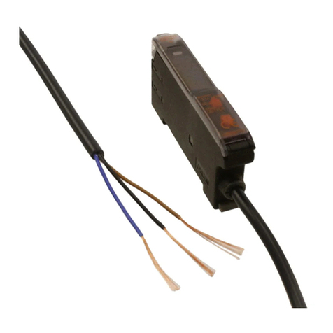
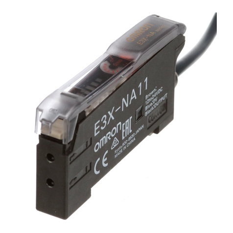
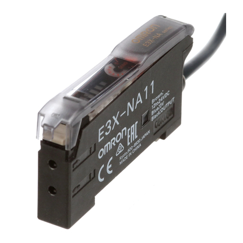
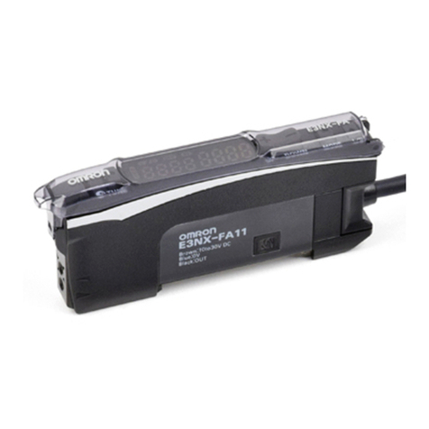
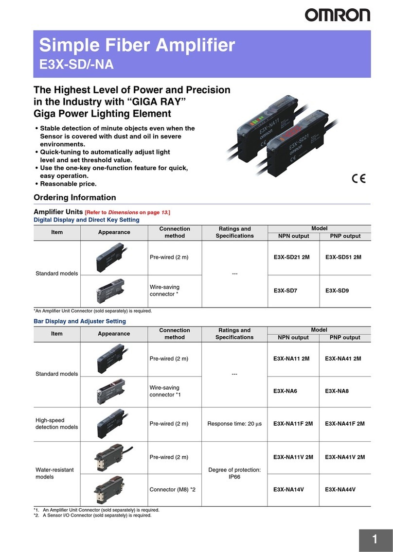
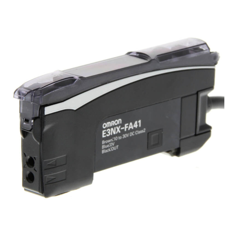
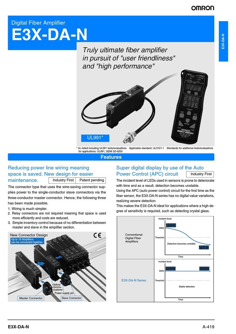
Omron E3X-DA-N series User manual

R
Digital Fiber-Optic Amplifier E3X-DA-N
Wire-Saving Amplifiers Offer Remote
Teaching, Easy-to-Repeat Settings
HRemote Control models have a unique
connector design that allows 16
amplifiers to be connected together
HRevolutionary remote control
programmer offers “copy and paste”
function for easy settings
HDetachable connector design enables
users to replace the amplifier without
disturbing wiring and sensing-head
installation
HAuto power control function enhances stable detection
HMark detection model has a blue light source to distinguish tough color combinations
HThree user-selectable displays: digital incident level, digital percent level and LED bar
graph display
HModels with dual analog/digital output increase application flexibility
Ordering Information
JAMPLIFIERS
Order connector cables separately for connector-ready models.
Type Appearance Applicable connector Output Part number
cables (order separately) NPN output PNP output
Remote control
amplifiers, digital E3X-CN master and slave
cables, single ended, 2 m ON/OFF output E3X-DA6 E3X-DA8
amplifiers, digital
output models cables, single ended, 2 m
(6.56 ft) length
Remote control
amplifiers, ON/OFF output and
analog output E3X-DA7 E3X-DA9
amplifiers,
analog/digital
output models
analog output
Amplifiers with
M8 connector XS3F single-ended cables
and XS3W double-ended
cables
ON/OFF output E3X-DA14V E3X-DA44V
Amplifiers with Prewired with 2 m ON/OFF output E3X-DA11-N E3X-DA41-N
cable (6.56 ft) cable ON/OFF output and
analog output E3X-DA21-N E3X-DA51-N
Mark-detecting
amplifier ON/OFF output E3X-DAB11-N ---

E3X-DA-NE3X-DA-N
2
JREMOTE CONTROL PROGRAMMER
Appearance Power supply method Remarks Part number
Chargeable battery Head, cable, and AC adapter
are provided as accessories. E3X-MC11
JCONNECTOR CABLES
Type Appearance Cable length Amplifier No. of
conductors Part number
Master connector
(See Notes 1, 2) 2 m (6.56 ft) E3X-DA6, E3X-DA8 3E3X-CN11
(See Notes 1, 2) E3X-DA7, E3X-DA9 4E3X-CN21
Slave connector
(See Notes 1, 2) E3X-DA6, E3X-DA8 1E3X-CN12
(See Notes 1, 2) E3X-DA7, E3X-DA9 2E3X-CN22
Straight M8 connector,
single ended 2 m (6.56 ft) E3X-DA14V,
E3X-DA44V 4XS3F-M421-402-A
Right angle M8
connector, single ended 2 m (6.56 ft) E3X-DA14V,
E3X-DA44V 4XS3F-M422-402-A
Straight M8 connector,
double ended 2 m (6.56 ft) E3X-DA14V,
E3X-DA44V 4XS3W-M421-402-R
Note: 1. When using five E3X-DA6/DA7/DA8/DA9 amplifiers ganged together, order one master and four slave connector cables. The
master connector cable distributes a power signal to all the ganged amplifiers; slave connector cables handle output signal
transmission only.
Amplifier Units
Type NPN PNP
Digital output models
Analog/digital output
E3X-DA6
E3X-DA7 E3X-DA9
E3X-DA8 +
Applicable Connector Cables
Master Connector Slave Connector
E3X-CN11 (3-wire)
E3X-CN21 (4-wire) E3X-CN22 (2-wire)
E3X-CN12 (1-wire)
Amplifier Units (5 Units) +Master Connector (1), Slave Connector (4)
When Using 5 Sets
2. Stickers for Connectors are included as accessories.
JACCESSORIES
Type Appearance Remarks Part number
Mounting bracket For surface mounting the sensor E39-L143
DIN rail track 50 cm (1.64 ft) length PFP-50N
1 m (3.28 ft) length PFP-100N
End plate For DIN track mounting of amplifiers PFP-M
JFIBER-OPTIC CABLES
The E3X-DA-N amplifiers use Omron’s E32-series fiber-optic cables. With a choice of over 80 sensing heads, you are sure to find one
that matches your application requirements. A selection of E32 cables and their respective sensing distances are at the end of this data
sheet. Order fiber-optic cables separately.

E3X-DA-N E3X-DA-N
3
Specifications
JAMPLIFIER RATINGS/CHARACTERISTICS
Description Digital output Analog/digital output Mark-detection M8 connector,
Prewired Connector Prewired Connector Prewired digital output
Output type NPN output E3X-DA11-N E3X-DA6 E3X-DA21-N E3X-DA7 E3X-DAB11-N E3X-DA14V
PNP output E3X-DA41-N E3X-DA8 E3X-DA51-N E3X-DA9 --- E3X-DA44V
Light source (wavelength) Red LED (660 nm) Blue LED
(470 nm) Red LED (660 nm)
Power supply voltage 12 to 24 VDC ±10%, ripple (p-p) 10% max.
Power Normal 960 mW max. (current consumption: 40 mA max. at power supply voltage of 24 VDC)
consumption Economy mode 720 mW max. (current consumption: 30 mA max. at power supply voltage of 24 VDC)
Digital display
not lit 600 mW max. (current consumption: 25 mA max. at power supply voltage of 24 VDC)
Control output ON/OFF output NPN/PNP (depends on model) open collector; load cur-
rent: 50 mA max.; residual voltage: 1 V max. NPN open col-
lector; load cur-
rent: 50 mA
max.; residual
voltage: 1 V
max.
NPN/PNP
(depends on
model) open col-
lector; load current:
50 mA max.; resid-
ual voltage: 1 V
max.
Analog output --- Load 1 to 5 VDC,
10 kΩmin. --- ---
Operation
mode Switch
selectable Light-ON/Dark-ON operation
Circuit protection Reverse polarity, output short-circuit, mutual interference prevention
Response time High-speed 250 µs for operation and reset respectively
by mode Standard 1 ms for operation and reset respectively
Long distance 4 ms for operation and reset respectively
Sensitivity setting Teaching or manual method
Functions Timer function OFF-delay timer range: 0 to 20 ms (set in 1 ms increments); 20 to 200 ms (set in 5 ms increments)
Automatic
power control
(APC)
Fiber-optic current digital control --- Fiber-optic current
digital control
Zero-reset Display can be reset to zero when required (negative values can be displayed).
Initial reset Settings can be returned to defaults as required.
Monitor focus --- Upper and lower limits can
be set as required for every
100 digital values.
--- ---
Display Function (color) Operation indicator (orange), 7-segment digital incident level display (red), 7-segment digital inci-
dent level percentage display (red), threshold and excess gain 2-color indication bar (green and
red), 7-segment digital threshold display (red)
Timing Normal/peak-hold/bottom-hold, program selectable
Orientation Normal/reverse, program selectable
Optical axis adjustment Optical axis adjustment possible (flashing function)
Ambient illumination Illumination intensity at light-intercepting surface:
Incandescent lamp: 10,000 lx max.; Sunlight: 20,000 lx max.
Ambient
temperature Operating Groups of 1 to 3 Amplifiers: –25°C to 55°C (–13°F to 131°F)
Groups of 4 to11 Amplifiers: –25°C to 50°C (–13°F to 122°F)
Groups of 12 to16 Amplifiers: –25°C to 45°C (–13°F to 113°F)
with no icing or condensation
Storage –30°C to 70°C (–22°F to 158°F) with no icing or condensation
Ambient humidity Operating and storage: 35% to 85% with no condensation
Insulation resistance 20 MΩmin. at 500 VDC
Dielectric strength 1,000 VAC at 50/60 Hz for 1 minute
Vibration resistance 10 to 55 Hz with a 1.5-mm double amplitude for 2 hrs each in X, Y and Z directions
(This table continues on the next page.)
E3X-DA-NE3X-DA-N
4
Specifications Table –continued from previous page
Description Digital output Analog/digital output Mark-detection M8 connector,
Prewired Connector Prewired Connector Prewired digital output
Output type NPN output E3X-DA11-N E3X-DA6 E3X-DA21-N E3X-DA7 E3X-DAB11-N E3X-DA14V
PNP output E3X-DA41-N E3X-DA8 E3X-DA51-N E3X-DA9 --- E3X-DA44V
Shock resistance 500 m/s2, for 3 times each in X, Y and Z directions
Degree of protection IP50 IP66
Connection method Prewired,
standard
cable length:
2 m (6.56 ft)
Connector,
E3X–CN
connector
cables
Prewired,
standard
cable length:
2 m (6.56 ft)
Connector,
E3X–CN
connector
cables
Prewired,
standard
cable length:
2 m (6.56 ft)
M8 connector; use
XS3F or XS3W
connector cables
Weight (approx., packed state) 100 g 55 g 100 g 55 g 100 g 100 g
Material Case PBT
Cover Polycarbonate
JCONNECTOR CABLES
Part number E3X-CN11/21/22 E3X-CN12
Rated current 2.5 A
Rated voltage 50 V
Contact resistance 20 mΩmax. (20 mVDC max., 100 mA max.) (See Note 1)
No. of insertions 50 times (See Note 2)
Material Housing PBT
Contacts Phosphor bronze/gold-plated nickel
Weight (approx., packed state) 55 g 25 g
Note: 1. The specified value for the contact resistance pertains to the contact resistance between the Connector and the Amplifier Unit,
and the Connector and other neighboring Connectors. It also includes the conductor resistance of the cable.
2. The specified value represents the number of insertions into the Amplifier Unit.
JREMOTE CONTROL PROGRAMMER
Part number E3X-MC11
Power supply voltage Charged with AC adapter
Connection method Connected via adapter
Weight (approx.,
packed state) 580 g (complete kit)
120 g (remote control only)

E3X-DA-N E3X-DA-N
5
Nomenclature
JDIGITAL FIBER-OPTIC AMPLIFIER
Lock Button Level Display Setting Buttons
Operation Indicator (orange)
ON when output is ON.
OFF when output is OFF. Mode Selector
Selectable among SET, ADJ, and RUN modes.
Operation Mode Selector
Selectable between Light-ON and Dark-ON modes.
TEACH
MODE
JDISPLAY AND SPECIAL FUNCTION SETTINGS
Display Setting
The E3X-DA-N offers three display modes, which are Digital Incident Level display, Digital Percent display and Analog display.
•Digital Incident Level Display: the incident level is digitally displayed.
•Digital Percent Display: the threshold-based excess gain is displayed in percentage.
•Analog Display: threshold and excess gain is displayed by two-color (red and green) bar graph.
Special Function Setting
The E3X-DA-N series has various functions that give users more flexibility in meeting a variety of application requirements.
•Sensing Function: Enables users to choose either standard sensing distance mode, long sensing distance mode
or high speed mode
•Timer Function: Enables users to select various OFF-delay timer settings from 0 to 20 ms (set in 1 ms increments) and from 20 to
200 ms (set in 5 ms increments). OFF-delay timer lengthens the duration of a short, high-speed signal so that it can be recognized as
input to Programmable Controllers during a scan cycle.
•Flashing Function: Flashing red LED allows easier optical axis adjustment.
•Display Hold Setting: This function provides easy data reading during optical axis adjustment and high-speed detection by holding
the displayed value for a period of time. Displayed data gets updated every 2 seconds. Within the 2-second time frame, the maximum
or minimum value is displayed (data will be flashing).
•Display Orientation Setting: Reversible digital display provides easy data reading from any mounting orientation.
•Zero reset: When activated, this function sets the incident
level digital display to zero. This enables operators to easily
monitor the difference between the maximum incident level
and the minimum incident level.
•Initial reset: Enables users to easily program the amplifier
back to the default (factory) settings.
•Monitor focus: This feature is available on analog/digital
output models. Without “monitor focus”, the E3X-DA-N has to
analyze an incident level range of 0 to 4095 to process a 1 to
5 VDC analog output. With the “monitor focus”function, the
E3X-DA-N can narrow the range of the incident level to pro-
cess a 1 to 5 VDC analog input by defining an upper and
lower limit of the incident level. As as result, the sensor’s
resolution is increased.
Shift
Example: Zero reset used to calculate threshold setting
At maximum incident level At minimum incident level
Zero reset
Incident level
difference = 700
Threshold level is auto-
matically calculated: 350
1200 500
700 0
350
Monitor
output
Monitor
output
Digital value Digital value
Example: Monitor focus increases resolution over a narrow range Upper limit = 2400 and lower limit = 1000
Conventional monitor output Output with E3X-DA-N’s monitor focus

E3X-DA-NE3X-DA-N
6
Operation
JOUTPUT CIRCUITS
Out-
put Model Mode
selector Timing chart State of
output
transistor
Output circuit
NPN E3X-DA11-N
E3X-DAB11-N
E3X-DA6
E3X-DA14V
LIGHT
ON
(L/ON) T
ON
OFF
ON
OFF
Incident received
Incident not received
Operation indicator
(orange)
Output
transistor
Load (relay) Operate
Release
(Between brown and black)
Light ON Brown
Black
Blue
Control output
Load
Operation indicator (orange)
12 to
24 VDC
Photo-
electric
Sensor
main
circuit
Display
DARK
ON
(D/ON) T
ON
OFF
ON
OFF
Incident received
Incident not received
Operation indicator
(orange)
Output
transistor
Load (relay) Operate
Release
(Between brown and black)
Dark ON Blue
E3X-DA21-N
E3X-DA7 LIGHT
ON
(L/ON) T
ON
OFF
ON
OFF
Incident received
Incident not received
Operation indicator
(orange)
Output
transistor
Load (relay) Operate
Release
(Between brown and black)
Light ON Brown
Black
Orange
Blue
Control output
Load
Load
Operation indicator (orange)
12 to
24
VDC
Photo-
electric
Sensor
main
circuit Analog
output
1 to 5 V
47Ω
Display
DARK
ON
(D/ON) T
ON
OFF
ON
OFF
Incident received
Incident not received
Operation indicator
(orange)
Output
transistor
Load (relay) Operate
Release
(Between brown and black)
Dark ON Blue
Note: Load resistance: 10 kΩmin.
PNP E3X-DA41-N
E3X-DA8
E3X-DA44V
LIGHT
ON
(L/ON) T
ON
OFF
ON
OFF
Incident received
Incident not received
Operation indicator
(orange)
Output
transistor
Load (relay) Operate
Release
(Between blue and black)
Light ON
Load
Brown
Black
Blue
Control output
12 to
24
VDC
Operation indicator (orange)
Photo-
electric
Sensor
main
circuit
Display
DARK
ON
(D/ON) T
ON
OFF
ON
OFF
Incident received
Incident not received
Operation indicator
(orange)
Output
transistor
Load (relay) Operate
Release
(Between blue and black)
Dark ON Blue
(This table continues on the next page.)
E3X-DA-N E3X-DA-N
7
Output Circuits –continued from previous page
Out-
put Model Mode
selector Timing chart State of
output
transistor
Output circuit
PNP E3X-DA51-N
E3X-DA9 LIGHT
ON
(L/ON) T
ON
OFF
ON
OFF
Incident received
Incident not received
Operation indicator
(orange)
Output
transistor
Load (relay) Operate
Release
(Between blue and black)
Light ON
Load
Load
Brown
Black
Orange
Blue
Control output
12 to
24
VDC
Operation indicator (orange)
Photo-
electric
Sensor
main
circuit
Display
Analog output
1 to 5 V
47Ω
(see note)
DARK
ON
(D/ON) T
ON
OFF
ON
OFF
Incident received
Incident not received
Operation indicator
(orange)
Output
transistor
Load (relay) Operate
Release
(Between blue and black)
Dark ON Blue
Note: Load resistance: 10 kΩmin.
JTEACHING FUNCTIONS
Four teaching methods are available to simplify setup and to allow changes in settings on the fly. The E3X-DA-N offers a new feature,
“pinpoint teaching”for positioning
Teaching function Application Description
Maximum sensitivity setting Use this function for sensing objects without backgrounds or through–
beam sensing. It is ideal for detecting large objects.
Two-point teaching with or without
object Minute level differences as thin as a piece of paper can be detected.
Detection of semi-transparent objects or the discrimination of object color
is also possible.
One-point teaching without object Set the sensitivity without stopping objects. This function allows automat-
ic detection of differences between objects and the background. Use it to
detect small moving items or thin objects such as gold wire.
Pinpoint teaching for positioning Allows high precision positioning when detecting electronic components
and other small items.

E3X-DA-NE3X-DA-N
8
JMAXIMUM SENSITIVITY SETTING
(TEACHING)
Set the mode selector to “SET”to start teaching. The red level
display will flash if teaching error occurs. In this case, repeat the
entire teaching procedure.
Maximum Sensitivity Setting
1. Set the “SET ADJ RUN”switch to “SET”position.
2. Press the “TEACH”button for 3 seconds (min).
3. Teaching is complete when the level display changes from
red to green. Digital incident level will appear shortly after the
display changes from red to green.
(Red)
(Green)
1234
4. Set the “SET ADJ RUN”switch to “RUN”position to imple-
ment settings from the teach function.
JONE-POINT TEACH MODE
(WITHOUT OBJECT)
1. Set the “SET ADJ RUN”switch to “SET”position.
2. Press the “TEACH”button for approximately 1 second.
3. Teaching is complete when the red level display is lit.
Digital incident level will appear shortly after the red level
display is lit.
(Red)
1234
4. Set the “SET ADJ RUN”switch to “RUN”position to imple-
ment settings from the teach function.
5. The threshold is automatically set.
Note: Try the two-point teaching mode if the difference in level is
too fine.

E3X-DA-N E3X-DA-N
9
JTWO-POINT TEACH MODE
WITH/WITHOUT OBJECT
1. Set the “SET ADJ RUN”switch to “SET”position.
2. Press the “TEACH”button for approximately 1 second when
the object is at the sensing position.
Object
3. The red level display is lit.
(Red)
4. Remove the object from the sensing area, and press the
“TEACH”button for approximately 1 second.
5. Teaching is complete when the green level display is lit.
Digital incident level will appear shortly after the green dis-
play is lit. (The red level display will flash if a teaching error
occurs.)
(Green)
1234
6. Set the “SET ADJ RUN”switch to “RUN”position to imple-
ment settings from the teach function.
Note: The order of “with-object”and “without-object”setting pro-
cedures above can be reversed.
JPINPOINT TEACH MODE (POSITIONING)
1. Set the “SET ADJ RUN”switch to “SET”position.
2. Press the TEACH button for approximately 1 second with no
object
Object
3. The red level display is lit.
(Red)
4. Place the object in the desired position and press the TEACH
button for 3 seconds minimum.
Object
5. Teaching is complete when the green level display is lit. Digi-
tal incident level will appear shortly after the green display is
lit. (The red level display will flash if a teaching error occurs.)
(Green)
6. Set the “SET ADJ RUN”switch to “RUN”position to imple-
ment settings from the teach function.

E3X-DA-NE3X-DA-N
10
JDISPLAY SETTING
E3X-DA-N can be programmed to display digital incident level,
digital percent level or analog display.
1. Set the “SET ADJ RUN”switch to “RUN”position. Digital
incident level should appear in the display.
Factory-set to RUN
2. Press the “MODE”button until “123P”is displayed. Digital
percent level is now displayed.
Digital percent
3. Press the “MODE”button to activate the “Analog Incident
Level”display. Two color (red and green) bar graph should
appear in the display.
Analog incident level and threshold
4. Press the “MODE”button to return to the “Digital Incident
Level”display.
JSPECIAL FUNCTION SETTING
E3X-DA-N series has various functions that give users more
flexibility in solving a variety of application requirements such as
the following:
•Long sensing distance (Sensing Function)
•Faster response time (Sensing Function)
•Off-delay timer (Timer Function)
•Optical axis alignment (Flashing Function)
•Digital data display hold setting (Display Hold Setting)
•Data display orientation (Display Orientation Setting)
•Zero reset
•Initial reset
•Monitor focus
Sensing Function
1. Set the “SET ADJ RUN”switch to “SET”position.
2. Press the “MODE”button until “fs t”is displayed. The “Stan-
dard”sensing function (fs t) is the default setting. The
“Standard”sensing function provides the standard detecting
distance. Response time is 1 ms.
3. Press the “TEACH”button to obtain the “Long Distance”
sensing function. “F Ld”should appear on the display. The
“Long Distance”function provides a sensing distance that is
about 1.3 times that of the “Standard”detecting distance
(diffuse fiber in use). The “Long Distance”setting has a re-
sponse time of 4 ms.
4. Press the “TEACH”button to obtain the “High Speed”sens-
ing function. “F HS”should appear on the display. The “High
Speed”function provides a detection distance that is about
one-third of the standard distance (diffuse fiber in use). Re-
sponse time is 250 µs.
5. Press the “TEACH”button to return to the “Standard”sensing
function display.
6. Set the “SET ADJ RUN”switch to “RUN”position to imple-
ment settings from the teach function.
Timer Function
1. Set the “SET ADJ RUN”Switch to “SET”position.
2. Press the “MODE”button until “t––0”is displayed. “t––0 is the
default setting.
0 (Factory-set)
3. Press the “TEACH”button to set to the desired time setting:
1 ms increments from 0 to 20 ms
5 ms increments from 20 to 200 ms
200
Adjustable in
5-ms units
4. Set the “SET ADJ RUN”switch to “RUN”position to imple-
ment settings from the teach function.

E3X-DA-N E3X-DA-N
11
Flashing Function
1. Set the “SET ADJ RUN”switch to “SET”position.
2. Press the “MODE”button until “LOFF”is displayed. “LOFF is
the default setting.
Off (Factory-set)
3. Press the “TEACH”button to activate the “flashing”function.
Display should read “L On”
4. Press the “TEACH”button to return to the “LOFF”mode.
5. Set the “SET ADJ RUN”switch to “RUN”position to imple-
ment settings from the teach function.
Display Hold Setting Function
1. Set the “SET ADJ RUN”switch to “SET”position.
2. Press the “MODE”button until “HOFF”is displayed. “HOFF”
is the default setting.
Off (Factory-set)
3. Press the “TEACH”button to activate “Peak Hold”display.
Displayed data get updated every 2 seconds. The maximum
value is displayed.
Peak
4. Press the “TEACH”button to activate “Bottom Hold”display.
Displayed data gets updated every 2 seconds. The minimum
value is displayed.
Bottom
5. Press the “TEACH”button to return to the default setting.
“HOFF”.
Off
6. Set the “SET ADJ RUN”switch to “RUN”position to imple-
ment settings from the teach function.
Display Orientation Setting Function
1. Set the “SET ADJ RUN”switch to “SET”position.
2. Press the “MODE”button until “d123”is displayed. “d123”is
the standard setting.
Standard (Factory-set)
3. Press the “TEACH”button to change the orientation of the
display. “dE21”should now appear in the display.
4. Press the “TEACH”button to return to the standard setting,
“d123”.
5. Set the “SET ADJ RUN”switch to “SET”position to imple-
ment settings from the teach function.
JMONITOR FOCUS
1. Set the “SET ADJ RUN”switch to “SET”position.
2. Press the “MODE”button until “A–UP”is displayed.
3. Press the “TEACH”button to set the desired “upper limit
setting”of the incident level.
4. To set “lower limit setting,”press the “MODE”button until
“A–LO”is displayed. Press the “TEACH”button to set the
lower limit setting.
Note: It is not possible to set an “upper limit”that is lower than
the value of the “lower limit”. Conversely, it is not possible
to set a “lower limit”that is greater than the value of the
“upper limit”
5. Set the “SET ADJ RUN”switch to “RUN”position to imple-
ment settings from the teach function.

E3X-DA-NE3X-DA-N
12
JZERO RESET FUNCTION
When activated, this function sets the incident level digital display
to zero. This enables operators to easily monitor the difference
between the maximum and the minimum incident levels.
1. Set the “SET ADJ RUN”switch to “RUN”position.
2. Press the “TEACH”button for 1 second. A zero should ap-
pear in the display.
3. Press the “TEACH”and “MODE”buttons simultaneously for
3 seconds to return to the initial incident level display.
Hold down both for 3 s
JINITIAL RESET
This function enables users to cancel program input and reset
the amplifier back to the default (factory) setting
1. Set the “SET ADJ RUN”switch to “SET”position.
2. Press the “TEACH”and “MODE”buttons simultaneously for
5 seconds until “NO ?”is displayed.
Hold down both for 5 s
To cancel “Initial Reset”function, simply press the “MODE”
button.
Press to cancel.
To implement the “Initial Reset”function, first press the
“TEACH”button until “YES?”appears in the display.
Press the “MODE”button to execute the “Initial Reset”
function.
Press to execute initial reset.
3. Set the “SET ADJ RUN”switch to “RUN”position to imple-
ment settings from the teach function.
Engineering Data
JPARALLEL OPERATING RANGE (TYPICAL)
At max. sensitivity. (Use for optical axis adjustment at installation.)
E32-TC200
(Through-beam) E32-T11R
(Through-beam) E32-T11
(Through-beam)
Distance Y (mm)
Standard
Long distance
Distance Y (mm)
High speed Standard
Long distance
Distance Y (mm)
High speed
Standard
Long distance
Distance X (m)Distance X (m)Distance X (m)
High speed

E3X-DA-N E3X-DA-N
13
JOPERATING RANGE (TYPICAL)
With standard sensing object at max. sensitivity. (Use for the positioning of the object and Sensor.)
E32-DC200
(Reflective) E32-D33
(Reflective) E32-L25L
(Convergent Reflective)
Distance Y (mm)
High speed
Long distance Standard
Distance Y (mm)
High speed Standard
Long distance
Distance Y (mm)
Distance X (mm)Distance X (mm)Distance X (mm)
JEXCESS GAIN RATIO VS. DISTANCE (TYPICAL)
With standard sensing object. At max. sensitivity.
Standard
E32-TC200
(Through-beam) E32-DC200
(Reflective) E32-D21L
(Reflective)
Excess gain ratio
Long distance
High speed
Distance (m)
Long distance
Standard
High speed
Distance (mm)
Long distance
Standard
High speed
Distance (mm)
Excess gain ratio
Excess gain ratio
Oper-
ating
level
Oper-
ating
level
Oper-
ating
level
Sensing Distance vs.
Operating Range
E32-DC200 (Reflective)
Differential Travel vs.
Sensing Distance
E32-D11L (Reflective)
Repeat Accuracy vs.
Sensing Distance
E32-DC200 (Reflective)
Distance Y (mm)
0.1-dia.
copper
wire
0.02-dia.
copper
wire
0.4-dia.
copper wire
Distance X (mm)
Standard
High
speed Long
distance
Differential travel (mm)
Distance Differential travel
Distance (mm)
High
speed
Long
distance
Standard
Repeat accuracy
Sensing object: White paper
(µm)
Sensing object: White paper
Distance (mm)

E3X-DA-NE3X-DA-N
14
E32-TC200 (Through-beam) E32-DC200 (Diffuse)
Analog output (V)
Distance (mm)
Analog output (V)
Distance (mm)
JANALOG OUTPUT VS. DISTANCE (STANDARD MODE)
E32-TC200 (Through-beam) E32-TC200+E39-F1 (Through-beam)
Distance Y (mm)
Standard
Long distance
Distance Y (mm)
High
speed Standard Long
distance
Distance X (m)
High speed
Distance X (m)
JPARALLEL OPERATING RANGE (TYPICAL)
MARK DETECTION SENSOR E3X-DAB11-N
At max. sensitivity. (Use for optical axis adjustment at installation.)
E32-DC200 (Reflective) E32-CC200 (Reflective) E32-D11L (Convergent Reflective)
Distance Y (mm)
High speed
Long distance
Standard
Distance Y (mm)
High speed Standard
Long
distance
Distance Y (mm)
Distance X (mm)Distance X (mm)Distance X (mm)
High speed Standard
Long distance
JOPERATING RANGE (TYPICAL)
With standard sensing object at max. sensitivity. (Use for the positioning of the object and Sensor.)

E3X-DA-N E3X-DA-N
15
Dimensions
Unit: mm (inch)
JAMPLIFIERS WITH MALE CONTACTS FOR E3X-CN CONNECTOR CABLES
E3X-DA6
E3X-DA7
E3X-DA8
E3X-DA9
Hole for optical communications
Operation indicator
(orange)
Incident level display
Threshold level display
Two,
2.4 (0.09)
dia. fiber-
optic cable
ports
8 (0.31)
10.7 (0.42)
64.3 (2.53)
3 (0.12)
10
(0.39)
1.8
(0.07)
14 (0.55)
31.5
(1.24)
38.6 (1.52)
36.7 (1.44)
9.9
(0.39)
3.4
(0.13) 13
(0.51)
5.5 (0.22)
13.05
(0.51)
17.15
(0.67)
4.9 x 3 =
14.7 (0.58)
1.7
4.2
5.1 3.9 1.8
6.2 1.7
Mounting Holes
Two,
M3
16 (0.63)
Dimensions with Master Connector Connected
Dimensions with Slave Connector Connected
4.0 dia.
E3X-CN12:
2.6 dia.
E3X-CN22:
4.0 dia.
64.3 (2.53)
64.3 (2.53)
67.5 (2.66)
67.5 (2.66)
71 (2.80)
71 (2.80)
31.5
(1.24)
31.5
(1.24)
12.95
(0.51)
12.95
(0.51)
17.45
(0.69)
11.55
(0.45)
4 (0.16)
10
(0.39)
4 (0.16)
10
(0.39)

E3X-DA-NE3X-DA-N
16
JAMPLIFIERS WITH M8 CONNECTORS
Shown with Mounting Bracket attached
Use Omron XS3F and XS3W connector cables or comparable Brad Harrison NanoChangetcordsets.
E3X-DA14V
E3X-DA44V
Hole for optical
communications
Two, 2.4
(0.09) dia.
fiber-optic
cable
ports
Two, M3
The mounting bracket can
be attached to this side.
28.05 (1.10)
23.95 (0.94)
4.9 x 3 =
14.7 (0.58)
79.5 (3.13)
40 (1.57)
4.9 (0.19)
33
(1.30)
9.9
(0.39)
8 (0.31)
10.7 (0.42)
12
(0.47)
16
(0.63)
Mounting Holes
3.9
(0.15) 3.4
(0.13) 4.3
(0.17) 9.5
(0.37)
23.9 (0.94)
14.4
(0.57)
M8
2.8 (0.11)
11.2
(0.44)
37 (1.46)
16 (0.63)
67.2 (2.65) 11
(0.43)
23.9 (0.94) 16 (0.63)
3.4
(0.13)
5.4
(0.21)
3.4 (0.13) 5.4 (0.21)
JAMPLIFIER PREWIRED WITH CABLE
Shown with Mounting Bracket E39-L143 attached
E3X-DA11-N
E3X-DA21-N
E3X-DA41-N
E3X-DA51-N
E3X-DAB11-N Mark Detection
The mounting bracket can be attached to this side.
Two, 3.2 dia. holes Mounting bracket E39-L143
SUS304 stainless steel
Mounting Holes
Two,
M3
Hole for optical
communications
Cable (See Note)
Two, 2.4
(0.09) dia.
fiber-optic
cable
ports
8 (0.31)
10.7 (0.42) 16
(0.63)
17.15
(0.68)
13.05
(0.51)
4.9 x 3 =
14.7 (0.58)
64.3 (2.53)3 (0.12) 38.6 (1.52) 5.3 (0.21)
10
(0.39)
10.75
(0.42)
31.5
(1.24)
4.1 (0.16)
22.4 (0.88)
13
(0.51)
16 (0.63)
34.8 (1.37) 2.4 (0.09)
4 (0.16)
9.9
(0.39)
22.4 (0.88) 16 (0.63)
3.4
(0.13) 4.4
(0.17)
Note: With the E3X-DA11-N/DA41-N/DAB11-N, 4-dia., 3-conductor, vinyl-insulated round cables of cross-sectional area 0.45 mm2and
insulation diameter of 1.1 dia. are used.
With E3X-DA21-N/DA51-N, 4-dia., 4-conductor, vinyl-insulated round cables of cross-sectional area 0.2 mm2and insulation diam-
eter 1.1 dia. are used.

E3X-DA-N E3X-DA-N
17
JCONNECTORS
Master Connectors
E3X-CN11
E3X-CN21
See Note
4 (0.16) dia.
2.6
(0.10)
2.9
(0.11)
10.7
(0.42)
10
(0.39)
15.1
(0.59)
6.8
(0.27)
8.4
(0.33)
0.8
(0.03)
14.4
(0.57)
6
(0.24)
6 (0.24) 2000 (6.56 ft)
+50
0
4 (0.16)
30±2 (1.18±0.08)
50 (1.97)
+5
0
10±2
(0.39
±0.08)
Note: E3X-CN11: 4-dia., 3-conductor, vinyl-insulated round cable of cross-sectional area 0.2 mm2and insulation diameter 1.1 dia.
E3X-CN21: 4-dia., 4-conductor, vinyl-insulated round cable of cross-sectional area 0.2 mm2and insulation diameter 1.1 dia.
Slave Connectors
E3X-CN12
E3X-CN22
See Note
E3X-CN12: 2.6 (0.10) dia.
E3X-CN22: 4 (0.16) dia.
2.6 (0.10)
2.9
(0.11)
10
(0.39)
0.8 (0.03)
14.4
(0.57)
6
(0.24)
6 (0.24)
3
(0.12)
10.7
(0.42)
15.1
(0.59)
6.8
(0.27)
8.4
(0.33)
2000 (6.56 ft)
+50
0
4 (0.16)
30±2 (1.18±0.08)
50 (1.97)
10±2
(0.39
±0.08)
+5
0
Note: E3X-CN12: 2.6 dia., single-conductor, vinyl-insulated round cable of cross-sectional area 0.2 mm2and insulation dia. 1.1 dia.
E3X-CN22: 4-dia., 2-conductor, vinyl-insulated round cable of cross-sectional area 0.2 mm2and insulation diameter 1.1 dia.

E3X-DA-NE3X-DA-N
18
JREMOTE CONTROL PROGRAMMER
Optical Communication Head for
Remote Control (included)
AC adapter jack Communications jack
Connection indicatorMenu indicators
Output indicator
Channel
buttons
Teaching
button
Enter button
Mode
button
Function
button
Battery
indicators
Power supply button
Escape button
Mode display
Channel indicator
Communications jack
M5 ball plunger
Optical commu-
nications position
22 (0.87) 52.8 (2.08)
136
(5.35)
50 (1.97)
10
(0.39)
20
(0.79)
30.3
(1.19)
24.3
(0.96)
9.9
(0.39)
27.7
(1.09)
17.3
(0.68)
1.2
(0.05)
5.1
(0.20) 12.3
(0.48)
13.1
(0.51)
13.2
(0.52)
38.2 (1.50)
31.8 (1.25) 16.3
(0.64)
28.8 (1.13)
36.7 (1.44)31.2 (1.23)
51.3 (2.02) 5.6 (0.22)
E3X–MC11

E3X-DA-N E3X-DA-N
19
JACCESSORIES (ORDER SEPARATELY)
Mounting Bracket E39-L143
10 (0.39) min.
Two, 3.2 dia.
Four, R1.7
10.3
(0.41)
5.3
(0.21)
7.3 (0.29)
2.5
(0.10)
7
(0.28)
3 (0.12)
34.8 (1.37)
22 (0.87)
16 (0.63)
26.8 (1.06)
16 (0.63) 3 (0.12)
3 (0.12)
3.4
(0.13)
3.4 (0.13)
1
(0.04)
10.3
(0.41) 7 (0.28)
End Plate PFP-M
M4 spring washer
M4×8, pan-head screw
10
(0.39)
50 (1.97)
11.5
(0.45)
4.8 (0.19)
1.3
(0.05) 1.8 (0.07)
35.5 (1.40)
1 (0.04)
35.3 (1.39)
6.2 (0.24)10 (0.39)
1.8 (0.07)
Installation
JCONNECTION
Connection with K3NX-VD2jProcess Meter
E3X-DA-N
Analog
output Orange
+V
0 V Blue
Brown 12 VDC 80 mA*
12 to 24 VDC
K3NX-VD2j
*Use this service power supply for the Sensor with
reference to the power consumption of each
Sensor.
Note: 1. Various output boards are available for
the K3NX. Select an appropriate output
type per application requirements.
2. For details about the K3NX, refer to the
K3NX Data Sheet in Omron’s Digital
Panel Meters catalog or the K3NX
Operation Manual (N090).
3. This wiring is for the K3NX with DC power
supply specifications and the Analog/
Digital Sensor with DC power supply
specifications. Check respective power
supply specifications before wiring.

E3X-DA-NE3X-DA-N
20
JMOUNTING
Joining Amplifier Units
1. Mount the Amplifier Units one at at time onto the DIN rail.
2. Line up the clips and slide the Amplifier Units together, and
then press the units together until they click into place.
Clip Click into place
Separating Amplifier Units
Slide Amplifier Units away from each other, and remove from the
DIN rail one at a time. (Do not attempt to remove Amplifier Units
from the DIN rail without separating them first.)
Note: 1. The specifications for ambient temperature will vary
according to the number of Amplifier Units used
together. For details, refer to Ratings/Characteristics.
2. Always turn OFF the power supply before joining or
separating Amplifier Units.
Mounting the Optical Communication Head
Allow 20 mm (0.79 in) of space to mount the Optical
Communication Head on the DIN rail between a cabinet wall and
the first Amplifier Unit. For proper operation, position the Optical
Communication Head close to the nearest Amplifier Unit, so
there is less than a 5 mm (0.20 in) gap.
Allow 20 mm (0.79 in) to mount the Optical
Communication Head on DIN rail.
Mounting
1. Mount the front part of the Amplifier Unit onto mounting
bracket E39-L143 (included) or onto DIN rail.
2. Press the back part onto the mounting bracket or onto the
DIN rail.
(1) (2)
DIN rail
Removal
Pull the lock tab of the Amplifier Unit with a flat blade screwdriver
in direction (3) and lift the fiber insertion part in direction (4) as
shown below.
(4)
(3)
DIN rail
In the case of side mounting, attach the E39-L143 mounting
bracket on the Amplifier Unit first, and secure the Amplifier Unit
with M3 screws and washers. The diameter of the washers
should be no more than 6 mm.
Washers
(6-mm dia. max.)
Other manuals for E3X-DA-N series
3
Table of contents
Other Omron Amplifier manuals

Omron
Omron E3X-CN11 User manual

Omron
Omron E3Z-L User manual

Omron
Omron E3XDAC21S2M User manual

Omron
Omron E3NX-MA Series User manual

Omron
Omron E3X-NA - User manual

Omron
Omron E3X-DAC-S Series User manual

Omron
Omron E3X-NA - User manual

Omron
Omron E3X-DA-S Series User manual

Omron
Omron E3X-NH User manual

Omron
Omron E3X-NA - User manual

Omron
Omron SMARTSTEP Junior R7D-ZP User manual

Omron
Omron F10-C20 User manual

Omron
Omron V640 User manual

Omron
Omron E3X-SD Series User manual

Omron
Omron E3NX-MA Series User manual

Omron
Omron V640 User manual

Omron
Omron E9NC-AA0 User manual

Omron
Omron V1000 User manual

Omron
Omron K7L-AT50D User manual

Omron
Omron E3X-NA11 User manual