12 to 24 VDC (Allowable voltage
uctuation range: 10 to 30 VDC)
(Class 2 Power Supply only)
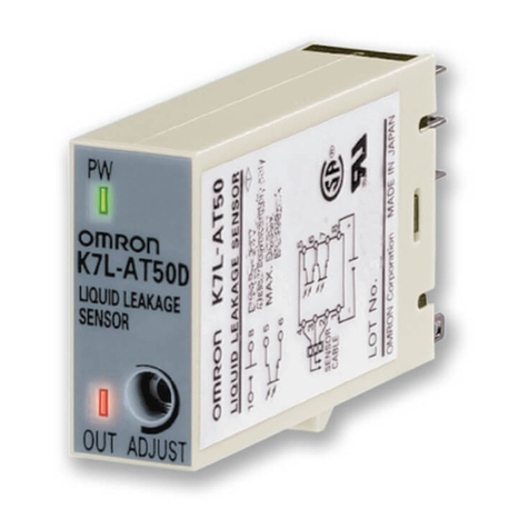
・K7L-AT50D
0 Ωto 50 MΩ, variable
Range 0: 0 to 250 kΩ
Range 1: 0 to 600 kΩ
Range 2: 0 to 5 MΩ
Range 3: 0 to 50 MΩ
Note:Setpins1,2,or3oftheDIP
switchonthesideoftheSensor
Amplifiertotheupwards position
accordingtotherangetobe
selected.Thesepins,whichare
arrangedinnumericalorderfrom
lefttoright,correspondto
ranges1through3.Besureto
setonlythecorrespondingpinto
theupwardposition.Forrange
0,setalltheseswitches
downwards.Theadjuster
(ADJUST)onthefrontpanel
allowsresistancechangesfrom
0Ωtotheupperlimitoftheset
range.Theadjusterissettothe
upperlimitasdefault.(Normally,
theadjustershouldbesettothe
upperlimit).
・K7L-UD
0 Ωto1MΩ,variable.
Note : Theadjusteronthefrontpanel
allowsresistancechangesfrom
0Ωtotheupperlimitoftheset
range.Theadjusterissettothe
upperlimitasdefault.(Normally,
theadjustershouldbesettothe
upperlimit).
Rated
power
supply
voltage
Operation
resistance
Model K7L-AT50D/AT50D-S
Model K7L-UD(F03-20T)
Liquid Leakage Sensor
Amplifier
1227587-5 C
INSTRUCTION MANUAL
Thank you for purchasing this OMRON product. Read
this instruction manual and thoroughly familiarize
yourself with the functions and characteristics of the
product before using it. Keep this instruction manual
for future reference.
Safety Precautions
Indicates a potentially hazardous
situation which, if not avoided, may
result in minor or moderate injury or in
property damage.
Do not touch the terminals.
Doing so may possibly result in electric
shock.
Do not allow pieces of metal or wire
clippings to enter the product while
power is being supplied. Electrical shock,
re or malfunction may result.
●Denition of Precautionary Information
●Precautionary Information
CAUTION
CAUTION
■Specications
K7L-AT50D : Terminal Block, Terminator and
scredriver are included.
K7L-AT50D-S : Terminal Block and screwdriver is
included. Please order F03-20T, the
terminator, spearately.
K7L-UD : Terminal Block, Terminator and
screwdriver are included in a box.
F03-20T : The terminator. Use together with
K7L-AT50D.
Model description /Accessories
Precautions for Safe Use
1.E
nvironmental Precautions
・Use and preserve within the proper temperature
and humidity described in the specications.
・Avoid preserving (including during
transportation) and using in a humid place, in a
corrosive gas environment, outdoors and in a
place which receives direct sunlight.
(To detect liquids with high impedances, do not
use in locations with high humidity.)
・Preserve and use without exposing to danger of
explosion, ammable dust, gas and vapor,
excessive dust, and saline spray or droplets.
・Avoid preserving (including during
transportation) and using in a place where
vibration and shock are strong.
・Do not store or use (including during
transportations) where an inuence of a static
electricity or an electric eld.
・Do not install the product near devices
generating strong high-frequency waves or
surges.
・Topreventinductivenoise,separateProduct
asfaraspossiblefromhigh-voltageor
high-currentlines.DonotplaceProductwiring
inparallelwithorinthesamepathas
high-voltageorhigh-currentlines.
・Donotinstallneardevicesthatgenerateheat,
suchasacoiloradevicecontainswinding
part,etc.
・
This is a class A product. In residential areas it
may cause radio interference, in which case the
user may be required to take adequate measures
to reduce interference.
2.Usage Precautions
・Read the instruction manual and catalog before
operating and maintaining the product.
・For items such as control power supply or power
supply to provide input power, as well as
distribution cable, use proper specied items.
[Recommended cable: three-core cabtire cable(s)
of completely insulated 600V 0.75mm2VCT]
・Use the product within the rated load.
・Check the usage, the wiring system and the
power source of this product again before using it.
・Pleasewipeofftheelectrodeareasoakedin
theliquid.
・Donottouchtheterminalswhilepoweris
beingsupplied.Notdoingsomayresultin
electricshock.
・DonotcleantheProductwithpaintthinneror
otherorganicsolvents.Usecommercial
alcohol.
・Donoholdandpullthecable
■Sockets
P2RF-08-E
16
4
85.5
max.
3.5-dia. hole
21.5 M3 screw
11.5
61 max.
35.5
39.5
3 dia.
2
48 max.
84 max.
(Including height of DIN track)
■Liquid Leakage Sensor Amplier
■Connections
K7L-AT50D : Total 60m max. (NOTE. Sensing Band length : 10m max.)
K7L-UD : Total 400m max.
234
423
5
6
7
8
4
3
2
1
K7L-AT50D/K7L-UD
(BOTTOM VIEW)
Liquid leakage
detection output
BURN OUT+
COM−
+
−
Terminator
F03-20T
(4-2)
2-4
100 mA at 30 VDC maximum
Open collector output
OUT+
Disconnection
detection output
Common
Signal
transmission
Level input 1
Level input 2
Commercial wiring cable
(more than 0.2 mm2)
12 VDC to 24 VDC
Terminal Block
for connection
F03-20
Liquid Sensing Band
F03-16PE
■Terminal Block ■Terminator Block
234
23
29.1
23.1
33
4
3.2 3.2 25
2
1
3
234
5×3=15 2.5
3.5 3.5
17.5
5.8
17
5.8
TYPE F03-20
23±0.2
2-M3
Mounting holes
3.2
3.2
25 TYPE F03-20T
18±0.2
2-M3
2-4
(4-2)
24.1
18.1
33
3.53.5
12.5
5.8
17
5.8
Mounting holes
・The resistance value adjuster is a precision component. Do not apply a torque to the resistance value adjuster
in excess of the specied one. Doing so may cause the resistance value adjuster to be damaged.
Applicable torque:
・Rotational torque : 9.81 m N・m max.
・Detent strength : 29.4 m N・m min.
・For liquid leakage detection, use Sensing Band for Omron made.
Omron Sensing Band : F03-15, F03-16PE, F03-16PT and F03-16SF.
Please refer to Precautions described in a datasheet.
・To wire correctly, please make sure terminal numbers.
・Check the application and power supply.
・Use DC power supply of "Class 2 Power Supply" as a condition of UL/CSA approval.
Precautions for Correct use
●Wiring
●Installation
●Adjuster
●Leakage Sensing Band
・The terminator must be needed for disconnection detection of wiring cable or wiring cable or Sensing Band.
・Be sure to connect the Sensing Band between K7L terminals 2 to 4, and the other end of Sensing Band must be
connected to a terminator (no matter the polarity of the terminator) (See Block Diagram for External
Connections below).
・Refer to Terminal Block for the connection, mounting method or materials.
・During disconnection detection, liquid leakage will not be detected. As well as, during liquid leakage
detection, disconnection will not be detected.
・Applicable torque : M3 scerws : 0.49 N・m type.
●Terminator (F03-20T, 2P)
・Use OMRON socket, P2RF-08/P2RF-08-E Surface Socket.
・Use the F03-20 Terminal Block included with the product.
To make connections, insert the cable from the side of the Terminal Block with a screwdriver inserted in the
top.
After work has been completed, ensure that the devices are still electrically connected.
The Terminal Block made with 66 nylon. Be sure to securely mount the Terminal Block with M3 scerws in a
place where it will not come into contact with chemicals.
・Applicable torque : M3 scerws : 0.49 N・m type.
・This product has been designed to limit the inuence of noise.
However, in order to limit the inuence of noise when the location to be monitored is far away, position the
Sensor and the Sensing Band/Point Sensor as close together as power supply and outputs far away.
●Surface Socket
●Terminal Block
●Wiring Cable
・Attach to a panel of thickness 1 to 5mm.
・In case of DIN rail clamping, attach the slider to the product and fasten it to the slider with the projecting
points of unit-side matched to the rail.
・When removing the product from the rail, insert screwdriver into the groove of slider and slide it outward.
12.8
28.8
46
Operate,Release:800msmax.
Disconnectiondetection:10smax.
Resetthepowersupplytostop
disconnectiondetection.
Response
time
105 % min. of operae resistance
Release
resistance
NPN open-collector transistor for both
liquid leakage detection an d
disconnection detection output with
100mA at 30 V DC max.
Note:ForoutputONwhenliquid
leakageisdetected:
Setpin4oftheDIPswich
locatedonthesideofthe
SensorAmplifierinthedown
position.
ForoutputOFFwhenliquid
leakageisdetected:
Setpin4oftheDIPswich
locatedonthesideofthe
SensorAmplifierintheup
position.
・K7L-AT50D
Wiring cable : 50 m max.
Sensing Band : 10 m max.
・K7L-UD
Overall cable length (wiring cable and
Sensing Band length total) : 400 m max.
Note: These values are possible on
condition that a completely
insulated 3-conductor VCT cable
with a thickness of 0.75 mm
2
and dielectric strength of 600 V
is used together with Liquid
Sensing Band Type F03-16PE
specied by OMRON. (A0.2-
mm
2
cable can also be used.)
Note: When using K7L by CE marking
or Safety Category 1 approved,
a power supply line is wired by
less than 10m.
Operation : -10 to +55 ℃
Operation : 45 to 85%RH
Output
conguration
Ambient
temperature
Ambient
humidity
Wiring
distance
Terminal block (for connecting wiring
cable and Sensing Band/Point Sensor)
F03-20T Terminator 1
(End unit for disconnection detection)
Screwdriver for ADJUST setting.
(Purchases the Sensing Band, Sensing
Band Sticker, Point Sensor, Wiring
cable, and Socket etc separately.)
The Terminal Block is 3P ; the Terminator
is 2P.
Accessories
Frequency : 10 to 150 Hz; Acceleration :
15m/s2, 10 sweeps of 8 min each in X, Y,
and Z directions.
Vibration
resistance
150 m/s23 times each in 3 axes, 6
directions.
Shock
resistance
Lit when power is being supplied :
PW LED (Green)
Lit when Liquid Leakage is detected :
OUT LED (Red)
The indicator ashes when disconnection
detected :
OUT LED (Red)
Indicator
Omron Companies shall not be responsible for conformity with
any standards, codes or regulations which apply to the
combination of the Product in the Buyer’s application or use of
the Product. At Buyer’s request, Omron will provide applicable
third party certication documents identifying ratings and
limitations of use which apply to the Product. This information by
itself is not sucient for a complete determination of the
suitability of the Product in combination with the end product,
machine, system, or other application or use. Buyer shall be solely
responsible for determining appropriateness of the particular
Product with respect to Buyer’s application, product or system.
Buyer shall take application responsibility in all cases.
NEVER USE THE PRODUCT FOR AN APPLICATION INVOLVING
SERIOUS RISK TO LIFE OR PROPERTY OR IN LARGE QUANTITIES
WITHOUT ENSURING THAT THE SYSTEM AS A WHOLE HAS BEEN
DESIGNED TO ADDRESS THE RISKS, AND THAT THE OMRON
PRODUCT(S) IS PROPERLY RATED AND INSTALLED FOR THE
INTENDED USE WITHIN THE OVERALL EQUIPMENT OR SYSTEM.
Suitability for Use
OMRON ELECTRONICS LLC.
One Commerce Drive Schaumburg, IL 60173-5302 U.S.A
Phone: 1-847-843-7900 Fax: 1-847-843-7787
OMRON EUROPE B.V.
Wegalaan 67-69, 2132 JD Hoofddorp The Netherlands
Phone: 31-23-56-81-300 Fax: 31-23-56-81-388
OMRON ASIA-PACIFIC PTE. LTD.
No.438AAlexandra Road #05-05/08(Lobby 2), Alexandra
Technopark, Singapore 119967
Phone: 65-6835-3011 Fax: 65-6835-2711
OMRON CORPORATION
3-4-10 Toranomon Minato-ku, Tokyo, 105-0001 Japan
Phone: 81-3-3436-7260 Fax: 81-3-3436-7261
Contact Information
