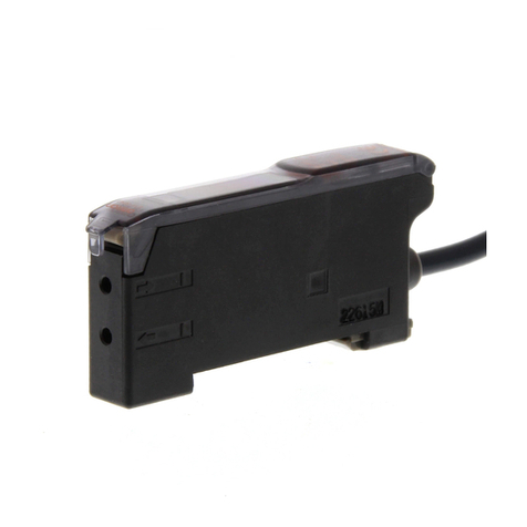
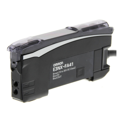
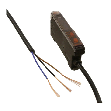
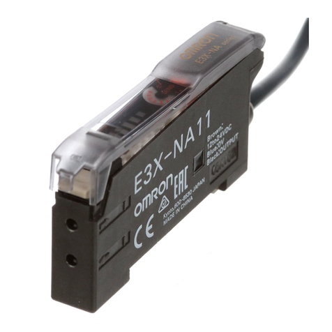
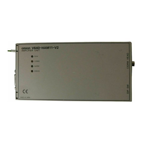
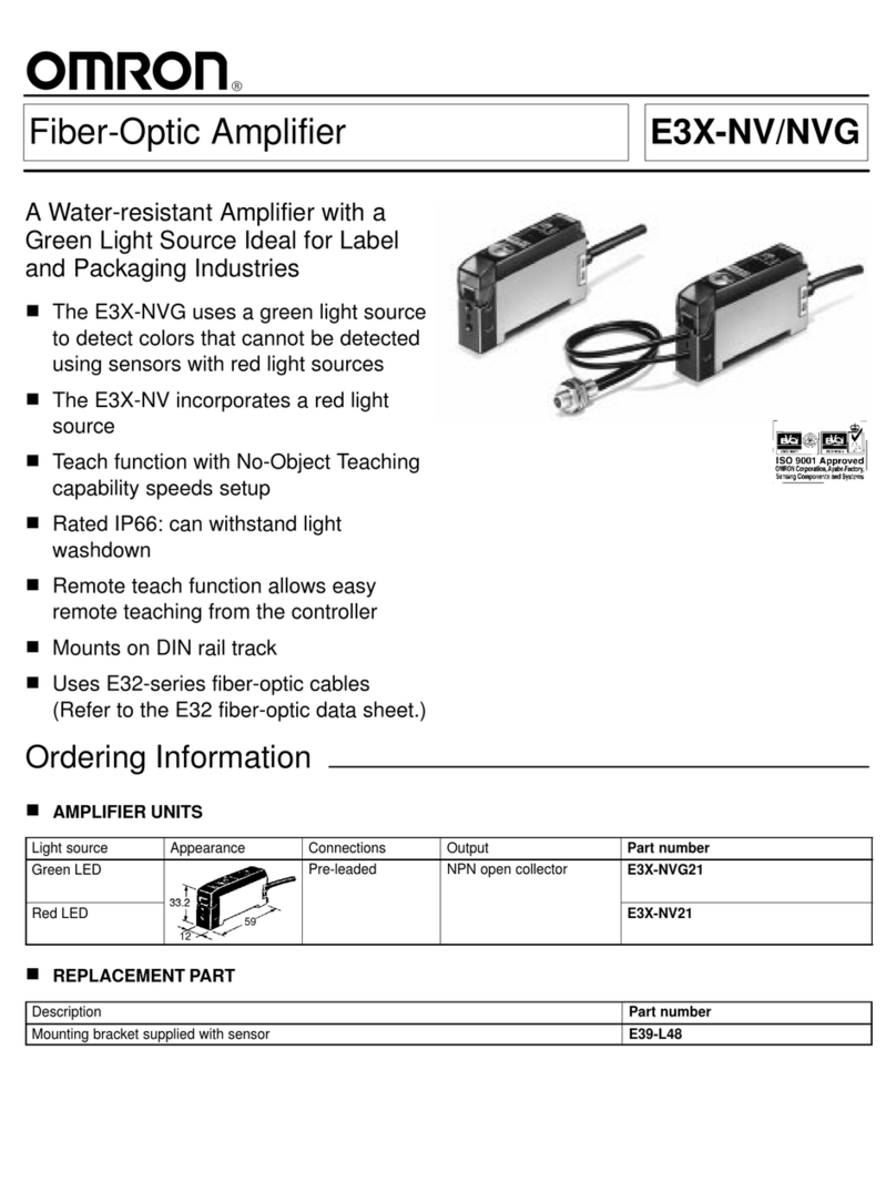
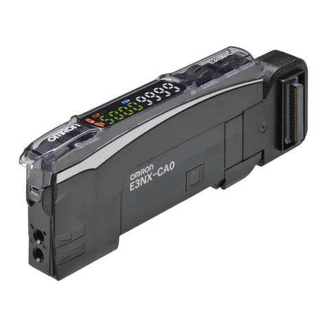
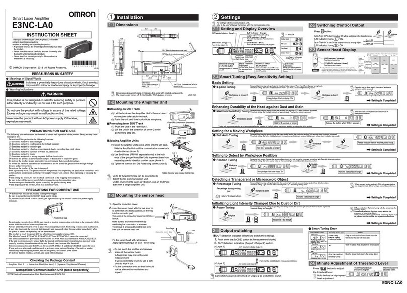
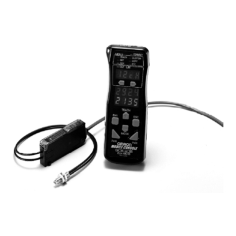
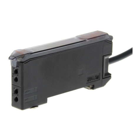
Omron E3X-NA - User manual

A-64 Photoelectric Sensors
Super Manual Fiber Amplifier
E3X-NA
Adjuster type standard that is the culmina-
tion of true ease and simplicity
Features
Instinctive LED bar displays of light levels
The previous manual type used the stability and incident level
indicators to display the light level change, which was difficult
to understand at a glance. The E3X-NA uses the LED bars to
display the light level, ensuring the light level change at a
glance.
Same "Wire-saving" Connector as
E3X-DA-N
OMRON's original wiring-saving connector, which was inher-
ited from the digital fiber amplifier E3X-DA-N, allows connec-
tion of up to 16 units.
* The vertical movement
of the LED light level
and operation display
shows the light level
at a glance.
Operation indicator
Approx. 20% or lower
Approx. 10% or lower
Approx. -10% or higher
Approx. -20% or higher
Unstable level
E3X-NA Conventional model
Power supply
pin
Optical
commu-
nications
Master connector Slave connector
Gang-mount up
to 16 Amplifiers

A-65E3X-NA
E3X-NA
Features
Reduced wiring and space requirements for
power lines
Example for 5 Amplifiers E3X-NA Series
Same Sensing Distance as Previous Long-
distance Models
200 mm Reflective Models
Approximately Seven Times the Detection
Accuracy
Applied Fiber: E32-T16P (screen fiber) set at 100 mm. E3X-
A1 1 (previous model) Minimum detection object: 2.0 mm dia.
E3X-NA 0.3 mm dia.
Addition of high-speed type and waterproof
type to the series
Optical Communications to Prevent Mutual
Interference
Optical communication between amplifiers prevents mutual
interference. Up to 5 fiber heads can be installed closely, ex-
cept E3X-NA#F.
Dimensions and Designs Inherited from the
E3X-DA-N Digital Fiber Amplifier
Relay connectors
Reduced Wiring and Space Requirements for Power Lines
Less space
required.
Power and output
lines required
for each amplifier.
15 lines
Power supplied from
master amplifier
through master
connector to
slave amplifiers.
7 lines
No relay connectors
required.
E3X-NA series
Example for 5 Amplifiers
Five previous
amplifiers
Output lines separate
from power
Output lines and power lines
Note: The above characteristics are ensured
with the E32-D11L Reflective Sensor
(long-distance model).
* The E3X-NA Series does not
have a long-distance model.
100mm
200
mm
E3X-NA
Long-distance:
E3X-H
Standard:
E3X-A
Standard model
50
mm
100
mm
150
mm
200
mm
Sensing
distance
Minimum
detection object:
Applied Fiber: E32-T16 (screen fiber) set at 100 mm.
E3X-A11 (previous model) E3X-NA
7 times
2.0 mm dia. 0.3 mm dia.
Optical
commu
nications
Up to 5
Amplifiers
Standard-feature
OFF delay timer
Digital Fiber Amplifier
E3X-DA-N
Non-removable hinged c
o
8-turn adjustment knob for
precise adjustment (with indicator)
Easy-to-see indicator
10mm
Super manual Amplifier
E3X-NA
Same 10-mm width as
the E3X-DA-N Digital
Fiber Amplifier
(Previously 12 mm) Same shape as the E3X-DA-N Digital Fiber Amplifier

A-66 Photoelectric Sensors
Ordering Information
Amplifier Units
Pre-wired
Connector type
Amplifier Units Connectors (Order Separately) Note: Stickers for Connectors are included as accessories.
Sensor I/O Connectors (Order separately)
Note: Refer to page NB-6 for details.
Accessories (Order Separately)
Item Shape Control output Model
NPN output PNP output
Standard models
ON/OFF output
E3X-NA11 E3X-NA41
High-speed detection E3X-NA11F E3X-NA41F
Mark-detecting models
E3X-NAG11 E3X-NAG41
Water-resistant models
E3X-NA11V E3X-NA41V
Item Shape Applicable Connector
(order separately) Control output Model
NPN output PNP output
Standard models
Master E3X-CN11
ON/OFF output
E3X-NA6 E3X-NA8
Slave E3X-CN12
Water-resistant models
(M8 Connector)
XS3F-M421-40#-A
XS3F-M422-40#-A E3X-NA14V E3X-NA44V
Item Shape Cable length No. of conductors Model
Master connector
2 m
3E3X-CN11
Slave connector 1 E3X-CN12
Size Cable type Shape Cable length Model
M8 Standard cable
2 m
4 conductors
XS3F-M421-402-A
5 m XS3F-M421-405-A
2 m XS3F-M422-402-A
5 m XS3F-M422-405-A
Precautions for ordering the connector type
Amplifier Units Applicable Connector (order separately)
Refer to the following tables when placing an order. Basical- Type NPN PNP
+
Master connector Slave connector
ly, Amplifier Units and connectors are sold separately.
Please place an order after referring to the combination giv-
Standard E3X-NA6
E3X-NA8
E3X-CN11 (3 wires) E3X-CN12 (1 wire)
When Using 5 Amplifier Units
Amplifier Units (5 Units)
+
1 Master Connector + 4 Slave Connectors
Straight
L-shaped
Mounting Brackets
Shape Applicable type Model Quantity
E3X-NA#
E3X-NA#F
E3X-NAG#
E39-L143
1
E3X-NA#V E39-L148
End Plate
Shape Model Quantity
PFP-M 1
A-67E3X-NA
E3X-NA
Applicable fiber unit type
Note: 1 . indicates a unit that can be cut freely.
2 . The values of the minimum sensing object for E3X-NA#(V) and E3X-NAG#through-beam models indicate those obtained where the sensing distance and
sensitivity are set to optimum values.
3 .The value of the minimum sensing object for E3X-NA#F through-beam models indicates that obtained at the rated sensing distance with the sensitivity set to
the optimum value.
4 .The size of standard sensing object is the same as the fiber core diameter (lens diameter for models with lens).
5 .The value of the minimum sensing object of the through-beam model assumes that the sensing distance and sensitivity are set to the optimum.
Long distance
Features Shape
Compatible
Amplifier
Units (E3X-)
Sensing distance (mm)
(Values in parentheses: when
using the E39-F1 Lens Unit)
Standard object (mm)
Minimum sensing object
(Opaque object) Typical
Model
Permissible
bending
radius
M4
NA#(V) 1.4 mm dia.
(0.03 mm dia.) E32-T11L
25 mm
NAG#
NA#F1.4 mm dia.
(0.5 mm dia.)
3.0 mm dia.
NA#(V) 1.4 mm dia.
(0.03 mm dia.) E32-T12LNAG#
NA#F1.4 mm dia.
(0.5 mm dia.)
M3
NA#(V) 0.9 mm dia.
(0.03 mm dia.) E32-T21L
10 mm
NAG#
NA#F0.9 mm dia.
(0.2 mm dia.)
2 mm dia.
(small diame-
ter)
NA#(V) 0.9 mm dia.
(0.03 mm dia.) E32-T22LNAG#
NA#F0.9 mm dia.
(0.2 mm dia.)
With M14
lens, ideal for
explosion-proof
applications
NA#(V) 10 mm dia.
(0.1 mm dia) E32-T17L 25 mm
NA#F10 mm dia.
(1.5 mm dia)
Free-cut
Red light Green light
Free-cut
M4 screw
700 (2,000)
130 (370)
210 (600)
Free-cut
3-mm dia.
700
130
210
Free-cut
M3 screw
200
40
60
Free-cut
2-mm dia.
200
40
60
Free-cut
M14 screw
14,000
4,200

A-68 Photoelectric Sensors
General purpose
Features Shape
Compatible
Amplifier
Units (E3X-)
Sensing distance (mm)
(Values in parentheses: when
using the E39-F1 Lens Unit)
Standard object (mm)
Minimum sensing object
(Opaque object) Typical
Model
Permissible
bending
radius
M4
NA#(V) 1.0 mm dia.
(0.03 mm dia.) E32-TC200 25 mm
NAG#
NA#F1.0 mm dia.
(0.2 mm dia.)
M4
NA#(V) 1.0 mm dia.
(0.03 mm dia.) E32-ET11R
1 mm
NAG#
NA#F1.0 mm dia.
(0.2 mm dia.)
3.0 mm dia.
NA#(V) 1.0 mm dia.
(0.03 mm dia.) E32-T12RNAG#
NA#F1.0 mm dia.
(0.2 mm dia.)
M3
Reflective
side-view
conversion
attachment
E39-F5
mountable
NA#(V)
1.0 mm dia.
(0.03 mm dia.)
E32-TC200A 25 mm
NAG#
NA#F1.0 mm dia.
(0.2 mm dia.)
M3
Minute work de-
tection
NA#(V) 0.5 mm dia.
(0.03 mm dia.) E32-TC200E 10 mm
NAG#
NA#F0.5 mm dia.
(0.1 mm dia.)
M3
NA#(V) 0.5 mm dia.
(0.03 mm dia.) E32-ET21R 1 mm
NAG#
NA#F0.5 mm dia.
(0.1 mm dia.)
Free-cut
M4 screw
400 (3,000)
75 (550)
120 (900)
Free-cut
M4 screw
280 (2,100)
50 (375)
80
Free-cut
3-mm dia.
280
50
80
Free-cut
(
)
M3 screw
360
65
100
Free-cut
M3 screw
100
20
30
Free-cut
M3 screw
60
12
18

A-69E3X-NA
E3X-NA
Note: 1 . indicates a unit that can be cut freely. The unit without the mark cannot be cut freely.
2 . The values of the minimum sensing object for E3X-NA#(V) and E3X-NAG#through-beam models indicate those obtained where the sensing distance and
sensitivity are set to optimum values.
3 .The value of the minimum sensing object for E3X-NA#F through-beam models indicates that obtained at the rated sensing distance with the sensitivity set to
the optimum value.
4 .The size of standard sensing object is the same as the fiber core diameter (lens diameter for models with lens).
5 .The value of the minimum sensing object of the through-beam model assumes that the sensing distance and sensitivity are set to the optimum.
Small diameter head
Flexible (resists breaking) (R4)
Features Shape
Compatible
Amplifier
Units (E3X-)
Sensing distance (mm)
(Values in parentheses: when
using the E39-F1 Lens Unit)
Standard object (mm)
Minimum sensing object
(Opaque object) Typical
Model
Permissible
bending
radius
2.0 mm dia.
Minute work
detection
NA#(V) 0.5 mm dia.
(0.03 mm dia.) E32-T22 10 mm
NAG#
NA#F0.5 mm dia.
(0.1 mm dia.)
2 mm dia. Small
work detection
NA#(V) 0.5 mm dia.
(0.03 mm dia.) E32-T22R 1 mm
NA#F0.5 mm dia.
(0.1 mm dia.)
With 1.2 mm
dia. sleeve
NA#(V) 1.0 mm dia.
(0.03 mm dia.) E32-TC200B
E32-TC200B4 25 mm
NAG#
NA#F1.0 mm dia.
(0.2 mm dia.)
With 0.9 mm
dia. sleeve
NA#(V) 0.5 mm dia.
(0.03 mm dia.) E32-TC200F
E32-TC200F4 10 mm
NAG#
NA#F0.5 mm dia.
(0.1 mm dia.)
Features Shape
Compatible
Amplifier
Units (E3X-)
Sensing distance (mm)
(Values in parentheses: when
using the E39-F1 Lens Unit)
Standard object (mm)
Minimum sensing object
(Opaque object) Typical
Model
Permissible
bending
radius
Ideal for
mounting on
moving sec-
tions (R4)
NA#(V) 1.0 mm dia.
(0.03 mm dia.) E32-T11
4 mm
NAG#
NA#F1.0 mm dia.
(0.2 mm dia.)
NA#(V) 0.5 mm dia.
(0.03 mm dia.) E32-T21NAG#
NA#F0.5 mm dia.
(0.1 mm dia.)
NA#(V) 0.5 mm dia.
(0.03 mm dia.) E32-T22BNAG#
NA#F0.5 mm dia.
(0.1 mm dia.)
Free-cut Free-cut
Red light Green light
Free-cut
2-mm dia.
100
20
30
Free-cut
2-mm dia.
60
18
Free-cut
1.2 dia.
M4 screw
( ): E32-
TC200B4
90mm(40mm)
400
75
120
Free-cut
M3 screw 0.9 dia.
90mm(40mm) ( ): E32-
TC200F4
100
20
30
Free-cut
M4 screw
360
65
100
M3 screw
100
18
30
1.5 mm dia.
100
18
30

A-70 Photoelectric Sensors
Side-view
Features Shape
Compatible
Amplifier
Units (E3X-)
Sensing distance (mm)
(Values in parentheses: when
using the E39-F1 Lens Unit)
Standard object (mm)
Minimum sensing object
(Opaque object) Typical
Model
Permissible
bending
radius
Long-distance
Space-saving
NA#(V) 1.0 mm dia.
(0.03 mm dia.) E32-T14L 25 mm
NAG#
NA#F1.0 mm dia.
(0.2 mm dia.)
Space-saving
NA#(V) 1.0 mm dia.
(0.03 mm dia.) E32-T14LR 1 mm
NA#F1.0 mm dia.
(0.2 mm dia.)
Small work
detection (small
diameter)
NA#(V) 0.5 mm dia.
(0.03 mm dia.) E32-T24 10 mm
NAG#
NA#F0.5 mm dia.
(0.3 mm dia.)
Small work
detection (small
diameter)
NA#(V) 0.5 mm dia.
(0.03 mm dia.) E32-T24R 1 mm
NA#F0.5 mm dia.
(0.3 mm dia.)
Screw-
mounting Model
NA#(V) 4.0 mm dia.
(0.03 mm dia.) E32-T14 25 mm
NAG#
NA#F4.0 mm dia.
(0.2 mm dia.)
Free-cut
3-mm dia.
240
45
70
Free-cut
3-mm dia.
110
33
Free-cut
1-mm dia.
90
12
27
Free-cut
1-mm dia.
30
9
Free-cut
1,800
330
540

A-71E3X-NA
E3X-NA
Chemical resistant
* Teflon is a registered trademark of Dupont Company and Mitsui Dupont Chemical Company for their fluoride resin.
Features Shape
Compatible
Amplifier
Units (E3X-)
Sensing distance (mm)
(Values in parentheses: when
using the E39-F1 Lens Unit)
Standard object (mm)
Minimum sensing object
(Opaque object) Typical
Model
Permissible
bending
radius
Teflon cover *
ensures envi-
ronmental re-
sistance
Operating am-
bient tempera-
ture: -30 to
+70°C
NA#(V)
4.0 mm dia.
(0.2 mm dia.)
E32-T12F
40 mm
NAG#
NA#F4.0 mm dia.
(0.7 mm dia.)
Teflon cover *
ensures envi-
ronmental re-
sistance Side-
view Operating
ambient tem-
perature: -30 to
+70°C
NA#(V)
3.0 mm dia.
(0.2 mm dia.)
E32-T14FNAG#
NA#F3.0 mm dia.
(0.7 mm dia.)
Teflon cover *
ensures envi-
ronmental re-
sistance
Operating am-
bient tempera-
ture: -40 to
+200°C
NA#(V) 1.0 mm dia.
(0.2 mm dia.)
E32-T81F 10 mm
NA#F1.0 mm dia.
(0.5 mm dia.)
Free-cut
5-mm dia.
1,600
300
480
Free-cut
m dia.
200
37
60
6-mm dia.
350
100

A-72 Photoelectric Sensors
Heat resistant
Features Shape
Compatible
Amplifier
Units (E3X-)
Sensing distance (mm)
(Values in parentheses: when
using the E39-F1 Lens Unit)
Standard object (mm)
Minimum sensing object
(Opaque object) Typical
Model
Permissible
bending
radius
150°C *1
Operating am-
bient tempera-
ture: -40 to
+150°C Fiber
sheath material:
Fluororesin
*1. For continuous operation, use the products within the temperature ranging from -40°C to 130°C.
NA#(V) 1.5 mm dia.
(0.03 mm dia.)
E32-ET51 35 mm
NA#F1.5 mm dia.
(1 mm dia.)
200°C
Operating am-
bient tempera-
ture: -40 to
+200°C Flexi-
ble: R10
Fiber sheath
material: Te-
flon*2
*2. Teflon is a registered trademark of Dupont Company and Mitsui Dupont Chemical Company for their fluoride resin.
NA#(V) 1.0 mm dia.
(0.2 mm dia.)
E32-T81R 10 mm
NA#F1.0 mm dia.
(0.5 mm dia.)
300°C *3
With spiral tube,
excellent in me-
chanical
strength Oper-
ating ambient
temperature: -
40 to +300°C
Fiber sheath
material: SUS
*3. Indicates the heat-resistant temperature at the fiber tip.
NA#(V) 1.0 mm dia.
(0.03 mm dia.)
E32-T61 25 mm
NA#F1.0 mm dia.
(0.5 mm dia.)
150°C
Side-view
minute work de-
tection Operat-
ing ambient
temperature:
-40 to +150°C
Fiber sheath
material: Fluo-
roresin
NA#(V) 1.0 mm dia.
(0.03 mm dia.)
E32-T54 35 mm
NA#F1.0 mm dia.
(0.3 mm dia.)
200 °C
L-shaped Fiber
sheath material:
SUS
NA#(V) 1.7 mm dia.
(0.03 mm dia.) E32-T84S 25 mm
NA#F1.7 mm dia.
(0.4 mm dia.)
Free-cut
M4 screw
400
120
M4 screw
180
50
M4 screw
300 (3,000)
90
Free-cut
2-mm dia.
130
35
3-mm dia.
700
210

A-73E3X-NA
E3X-NA
Note: 1 . indicates a unit that can be cut freely. The unit without the mark cannot be cut freely.
2 . The values of the minimum sensing object for E3X-NA#(V) and E3X-NAG#through-beam models indicate those obtained where the sensing distance and
sensitivity are set to optimum values.
3 .The value of the minimum sensing object for E3X-NA#F through-beam models indicates that obtained at the rated sensing distance with the sensitivity set to
the optimum value.
4 .The size of standard sensing object is the same as the fiber core diameter (lens diameter for models with lens).
5 .The value of the minimum sensing object of the through-beam model assumes that the sensing distance and sensitivity are set to the optimum.
Grooved
Narrow vision field
Features Shape
Compatible
Amplifier
Units (E3X-)
Sensing distance (mm)
(Values in parentheses: when
using the E39-F1 Lens Unit)
Standard object (mm)
Minimum sensing object
(Opaque object) Typical
Model
Permissible
bending
radius
Detection of film
sheet, beam
axis adjust-
ment unneces-
sary, easy
installation
NA#(V) 4.0 mm dia.
(0.1 mm dia.) E32-G14 25 mm
NAG#
NA#F4.0 mm dia.
(1.0 mm dia.)
Features Shape
Compatible
Amplifier
Units (E3X-)
Sensing distance (mm)
(Values in parentheses: when
using the E39-F1 Lens Unit)
Standard object (mm)
Minimum sensing object
(Opaque object) Typical
Model
Permissible
bending
radius
Ideal for wafer
detection
NA#(V) 1.7 mm dia.
(0.5 mm dia.) E32-T22S
10 mm
NA#F
Side-view
Ideal for wafer
NA#(V) 2.0 mm dia.
(0.03 mm dia.) E32-T24S
NA#F2.0 mm dia.
(0.5 mm dia.)
Free-cut Free-cut
Free-cut 10
10
10
Free-cut
3-mm dia.
1,000
300
Free-cut 3.5 mm dia.
x 3 700
210

A-74 Photoelectric Sensors
Area sensing
* The sensing distance is 100 mm and the value can be detected in each detection area. (The sensing object diameter is the value in stationary status.)
Features Shape
Compatible
Amplifier
Units (E3X-)
Sensing distance (mm)
(Values in parentheses: when
using the E39-F1 Lens Unit)
Standard object (mm)
Minimum sensing object
(Opaque object) Typical
Model
Permissible
bending
radius
Multi-point de-
tection (4 head)
NA#(V) 2.0 mm dia.
(0.03 mm dia.) E32-M21 25 mm
NA#F2.0 mm dia.
(0.3 mm dia.)
Detects in a 30
mm area
NA#(V)
(0.5 mm dia.) *
E32-T16W 10 mm
NAG#
NA#F (4.0 mm dia.) *
Detects in a 30
mm area
NA#(V) (0.5 mm dia.) *
E32-T16WR 1 mm
NA#F(4.0 mm dia.) *
Side-view type
Ideal for appli-
cations that do
not have suffi-
cient depth
NA#(V)
(0.3 mm dia.) *
E32-T16J 10 mm
NAG#
NA#F (2.0 mm dia.) *
Side-view type
Ideal for appli-
cations that do
not have suffi-
cient depth
NA#(V) (0.3 mm dia.) *
E32-T16JR 1 mm
NA#F(2.0 mm dia.) *
Detection in
area of 10 mm
width, long dis-
tance
NA#(V)
(0.9 mm dia.) *
E32-T16 25 mm
NAG#
NA#F (1.5 mm dia.) *
Stable detec-
tion of small
work in wide
area Protective
structure: IEC
60529 IP50
NA#(V)
(0.3 mm dia.) *
E32-T16P 10 mm
NAG#
NA#F (2.0 mm dia.) *
Stable detec-
tion of small
work in wide
area Protective
structure: IEC
60529 IP50
NA#(V) (0.3 mm dia.) *
E32-T16PR 1 mm
NA#F(2.0 mm dia.) *
M3 screw
300
90
Free-cut
30mm
920
170
270
Free-cut
30mm
690
200
Free-cut
11mm
520
95
150
Free-cut
11mm
390
110
Free-cut
10mm
1,500
275
450
Free-cut
11mm
600
110
180
Free-cut
11mm
450
130

A-75E3X-NA
E3X-NA
Note: 1 . indicates a unit that can be cut freely. The unit without the mark cannot be cut freely.
2 .The values of the minimum sensing object indicate those obtained at a distance where the smallest object can be sensed with the Reflective Fiber Unit.
Long distance
* Sensing distance indicates values for white paper.
Features Shape
Compatible
Amplifier
Units (E3X-)
Sensing distance (mm)
Standard object (mm)
Minimum sensing object
(Gold wire) typical
Model
Permissible
bending
radius
M6
NA#(V)
250 x 250
(0.01 mm dia.)
E32-D11L
25 mm
NAG#50 x 50
(0.1 mm dia.)
NA#F
100 x 100
(0.015 mm dia.)
3 mm dia.
(small diameter)
NA#(V)
150 x 150
(0.01 mm dia.)
E32-D12NAG#25 x 25
(0.1 mm dia.)
NA#F50 x 50
(0.015 mm dia.)
M4
NA#(V)
100 x 100
(0.01 mm dia.)
E32-D21L
10 mm
NAG#25 x 25
(0.1 mm dia.)
NA#F25 x 25
(0.015 mm dia.)
3 mm dia.
(small diame-
ter)
NA#(V)
100 x 100
(0.01 mm dia.)
E32-D22LNAG#25 x 25
(0.1 mm dia.)
NA#F25 x 25
(0.015 mm dia.)
Free-cut Free-cut
Red light Green light
Free-cut
M6 screw
200
35
65
Free-cut
3-mm dia.
120
20
40
Free-cut
M4 screw
50
10
17
Free-cut
3-mm dia.
50
10
17

A-76 Photoelectric Sensors
General purpose
* Sensing distance indicates values for white paper.
Features Shape
Compatible
Amplifier
Units (E3X-)
Sensing distance (mm)
Standard object (mm)
Minimum sensing object
(Gold wire) typical
Model
Permissible
bending
radius
M6
NA#(V)
200 x 200
(0.01 mm dia.)
E32-DC200 25 mm
NAG#50 x 50
(0.1 mm dia.)
NA#F75 x 75
(0.015 mm dia.)
M6
NA#(V)
150 x 150
(0.01 mm dia.)
E32-ED11R
1 mm
NAG#25 x 25
(0.1 mm dia.)
NA#F50 x 50
(0.02 mm dia.)
3.0 mm dia.
NA#(V)
150 x 150
(0.01 mm dia.)
E32-D12RNAG#25 x 25
(0.1 mm dia.)
NA#F50 x 50
(0.02 mm dia.)
M3 (small di-
ameter)
NA#(V) 50 x 50
(0.01 mm dia.)
E32-DC200E 10 mm
NAG#25 x 25
(0.1 mm dia.)
NA#F25 x 25
(0.02 mm dia.)
M3 (small di-
ameter)
NA#(V) 25 x 25
(0.01 mm dia.) E32-ED21R
1 mm
NA#F25 x 25
(0.03 mm dia.)
3 mm dia.
(small diame-
ter)
NA#(V) 25 x 25
(0.01 mm dia.) E32-D22R
NA#F25 x 25
(0.03 mm dia.)
Free-cut
M6 screw
150
25
50
Free-cut
M6 screw
90
15
30
Free-cut
3-mm dia.
90
15
30
Free-cut
M3 screw
36
6
12
Free-cut
M3 screw
15
5
Free-cut
3-mm dia.
15
5

A-77E3X-NA
E3X-NA
Thin fiber
* Sensing distance indicates values for white paper.
Flexible (resists breaking) (R4)
* Sensing distance indicates values for white paper.
Features Shape
Compatible
Amplifier
Units (E3X-)
Sensing distance (mm)
Standard object (mm)
Minimum sensing object
(Gold wire) typical
Model
Permissible
bending
radius
With 2.5 mm
sleeve
NA#(V) 200 x 200
(0.01 mm dia.)
E32-DC200B
E32-DC200B4
25 mm
NAG#50 x 50
(0.1 mm dia.)
NA#F75 x 75
(0.015 mm dia.)
With 1.2 mm
dia. sleeve
NA#(V) 50 x 50
(0.01 mm dia.)
E32-DC200F
E32-DC200F4 10 mm
NAG#25 x 25
(0.1 mm dia.)
NA#F25 x 25
(0.02 mm dia.)
0.8 mm minute
work detection
NA#(V) 25 x 25
(0.01 mm dia.) E32-D33 4 mm
NA#F25 x 25
(0.03 mm dia.)
0.5 mm dia.
Very small
work detection
NA#(V) 25 x 25
(0.01 mm dia.) E32-D331 4 mm
NA#F25 x 25
(0.05 mm dia.)
Features Shape
Compatible
Amplifier
Units (E3X-)
Sensing distance (mm)
Standard object (mm)
Minimum sensing object
(Gold wire) typical
Model
Permissible
bending
radius
Ideal for instal-
lation on mov-
ing sections
(R4)
NA#(V) 150 x 150
(0.01 mm dia.)
E32-D11
4 mm
NAG#25 x 25
(0.1 mm dia.)
NA#F50 x 50
(0.015 mm dia.)
NA#(V) 25 x 25
(0.01 mm dia.) E32-D21
NA#F25 x 25
(0.02 mm dia.)
NA#(V) 25 x 25
(0.01 mm dia.)
E32-D21BNAG#25 x 25
(0.1 mm dia.)
NA#F25 x 25
(0.02 mm dia.)
NA#(V) 25 x 25
(0.01 mm dia.) E32-D22B
NA#F25 x 25
(0.02 mm dia.)
Free-cut
2.5 dia.
M6 screw
90mm(40mm)
( ): E32-
DC200B4
150
25
50
Free-cut
1.2 dia.
M3 screw
90mm(40mm)
( ): E32-
DC200F4
36
6
12
Free-cut
3-mm dia.
0.8-mm dia.
10
3.3
2-mm dia.
0.5-mm dia.
1.5
0.5
Free-cut
Free-cut
Free-cut
M6 screw
90
15
30
M3 screw
15
5
M4 screw
15
2.4
5
1.5-dia.
7
2.3

A-78 Photoelectric Sensors
Note: 1 . indicates a unit that can be cut freely. The unit without the mark cannot be cut freely.
2 .The values of the minimum sensing object indicate those obtained at a distance where the smallest object can be sensed with the Reflective Fiber Unit.
Coaxial
* Sensing distance indicates values for white paper.
Features Shape
Compatible
Amplifier
Units (E3X-)
Sensing distance (mm)
Standard object (mm)
Minimum sensing object
(Gold wire) typical
Model
Permissible
bending
radius
M6 precision
positioning
NA#(V)
200 x 200
(0.01 mm dia.)
E32-CC200
25 mm
NAG#50 x 50
(0.1 mm dia.)
NA#F75 x 75
(0.015 mm dia.)
3 mm dia.
(small diame-
ter) precision
positioning
NA#(V)
100 x 100
(0.01 mm dia.)
E32-D32LNAG#25 x 25
(0.1 mm dia.)
NA#F50 x 50
(0.02 mm dia.)
M3 precision
positioning
Small spot lens
(E39-F3A-5/
F3B/F3C)
mountable
NA#(V) 50 x 50
(0.01 mm dia.)
E32-EC31NAG#25 x 25
(0.1 mm dia.)
NA#F25 x 25
(0.02 mm dia.)
M3 precision
positioning
Small spot lens
(E39-F3A-5/
F3B/F3C)
mountable
NA#(V) 25 x 25
(0.01 mm dia.)
E32-EC41
NA#F25 x 25
(0.02 mm dia.)
2 mm dia. preci-
sion positioning
Small spot lens
(E39-F3A)
mountable
Spot diameter
0.1 to 0.6 mm
variable
NA#(V) 25 x 25
(0.01 mm dia.)
E32-C42
NA#F25 x 25
(0.02 mm dia.)
2 mm dia. preci-
sion positioning
Small spot lens
(E39-F3A)
mountable
Spot diameter
0.5 to 1 mm
variable
NA#(V) 50 x 50
(0.01 mm dia.)
E32-D32NAG#25 x 25
(0.1 mm dia.)
NA#F25 x 25
(0.02 mm dia.)
Free-cut Free-cut
Red light Green light
Free-cut
M6 screw
150
25
50
Free-cut
3-mm dia.
80
12
25
Free-cut
M3 screw
40
6
13
M3 screw
15
5
( )
2-mm dia.
15
5
Free-cut
( )
2-mm dia.
40
6
13

A-79E3X-NA
E3X-NA
Side-view
* Sensing distance indicates values for white paper.
Chemical resistant
Features Shape
Compatible
Amplifier
Units (E3X-)
Sensing distance (mm)
Standard object (mm)
Minimum sensing object
(Gold wire) typical
Model
Permissible
bending
radius
6 mm dia. Long
distance
NA#(V) 50 x 50
(0.03 mm dia.)
E32-D14L 25 mm
NAG#25 x 25
(0.3 mm dia.)
NA#F25 x 25
(0.03 mm dia.)
6 mm dia.
NA#(V) 25 x 25
(0.03 mm dia.)
E32-
D14LR 1 mm
NA#F
2 mm dia.
(small diameter)
Space saving
NA#(V) 25 x 25
(0.03 mm dia.)
E32-D24 10 mm
NAG#25 x 25
(0.3 mm dia.)
NA#F25 x 25
(0.03 mm dia.)
2 mm dia.
(small diameter)
Space saving
NA#(V) 25 x 25
(0.03 mm dia.) E32-D24R 1 mm
NA#F
Features Shape
Compatible
Amplifier
Units (E3X-)
Sensing distance (mm)*1
*1. Sensing distance indicates values for white paper.
Standard object (mm)
Minimum sensing object
(Gold wire) typical
Model
Permissible
bending
radius
Teflon-covered *2
High environ-
mental resistance
Operating ambient
temperature:
-30 to +70°C
*2. Teflon is a registered trademark of Dupont Company and Mitsui Dupont Chemical Company for their fluoride resin.
NA#(V)
100 x 100
(0.03 mm dia.)
E32-D12F 40 mm
NAG#25 x 25
(0.3 mm dia.)
NA#F25 x 25
(0.03 mm dia.)
Free-cut 6-mm dia.
40
10
13
Free-cut 6-mm dia.
16
5
Free-cut
2-mm dia.
15
2.4
5
Free-cut
2-mm dia.
7
2.3
Free-cut
6-mm dia.
50
8
16

A-80 Photoelectric Sensors
Heat resistant
Area sensing
* Sensing distance indicates values for white paper.
Features Shape
Compatible
Amplifier
Units (E3X-)
Sensing distance (mm)*1
*1. Sensing distance indicates values for white paper.
Standard object (mm)
Minimum sensing object
(Gold wire) typical
Model
Permissible
bending
radius
150°C *2 Oper-
ating ambient
temperature:
-40 to +150°C
Fiber sheath
material: Fluo-
roresin
*2. For continuous operation, use the products within the temperature ranging from -40°C to 130°C.
NA#(V)
150 x 150
(0.03 mm dia.)
E32-ED51 35 mm
NA#F50
x
50
(0.03 mm dia.)
300°C *3 Oper-
ating ambient
temperature:
-40 to +300°C
Fiber sheath
material: SUS
*3. Indicates the heat-resistant temperature at the fiber tip.
NA#(V)
100 x 100
(0.03 mm dia.)
E32-D61
25 mm
NA#F25 x 25
(0.03 mm dia.)
400°C Operat-
ing ambient
temperature:
-40 to +400°C
Fiber sheath
material: SUS
NA#(V) 50 x 50
(0.03 mm dia.)
E32-D73
NA#F25 x 25
(0.03 mm dia.)
Features Shape
Compatible
Amplifier
Units (E3X-)
Sensing distance (mm)
Standard object (mm)
Minimum sensing object
(Gold wire) typical
Model
Permissible
bending
radius
Side-view type
Wide detection
of wide area
NA#(V)
100 x 100
(0.03 mm dia.)
E32-D36P1 25 mm
NA#F50 x 50
(0.03 mm dia.)
Free-cut
M6 screw
120
40
M6 screw
45
15
M4 screw 1.25-mm dia
.
30
10
Free-cut 75
25

A-81E3X-NA
E3X-NA
Note: 1 . indicates a unit that can be cut freely. The unit without the mark cannot be cut freely.
2 .The values of the minimum sensing object indicate those obtained at a distance where the smallest object can be sensed with the Reflective Fiber Unit.
Retroreflective
* Sensing distance indicates values for white paper.
Limited reflective
* Sensing distance indicates values for white paper.
Features Shape
Compatible
Amplifier
Units (E3X-)
Sensing distance (mm)
Standard object (mm)
Minimum sensing object
(Gold wire) typical
Model
Permissible
bending
radius
Opaque object
detection
NA#(V) 35.0 mm dia.
(0.3 mm dia.) E32-R21
+
E39-R3
(Attachment)
10 mm
NA#F35.0 mm dia.
(0.5 mm dia.)
Opaque object
detection Oper-
ating ambient
temperature: -
25 to +55°C
Protective
structure: IEC
60529 IP66
NA#(V) 35.0 mm dia.
(0.6 mm dia.) E32-R16
+
E39-R1
(Attachment)
25 mm
NA#F35.0 mm dia.
(0.4 mm dia.)
Features Shape
Compatible
Amplifier
Units (E3X-)
Sensing distance (mm)
Standard object (mm)
Minimum sensing object
(Gold wire) typical
Model
Permissible
bending
radius
Ideal for
positioning of
crystal glass
NA#(V)
--- E32-L56E1
E32-L56E2 35 mm
NA#F
Wafer/small
height differ-
ence detection
Operating
ambient tem-
perature:
-40 to +105°C
Protective
structure: IEC
60529 IP50
NA#(V) 25 x 25
(0.015 mm dia.)
E32-L24L
10 mm
NA#F25 x 25
(0.03 mm dia.)
NA#(V) 25 x 25
(0.015 mm dia.)
E32-L25L
NA#F25 x 25
(0.03 mm dia.)
Wafer/small
height differ-
ence detection
Protective
structure: IEC
60529 IP50
NA#(V) 25 x 25
(0.015 mm dia.) E32-L25
25 mm
NA#F25 x 25
(0.03 mm dia.)
NA#(V) 25 x 25
(0.015 mm dia.) E32-L25A
NA#F25 x 25
(0.03 mm dia.)
Free-cut Free-cut
Red light
Free-cut
E39-R3
reflector
M6 screw
10 to 250
10 to 250
Free-cut
E39-R1
reflector
150 to 1500
150 to 1000
Free-cut 4 to 12
4 to 12
Free-cut
4 ±2
4 ±2
7.2±1.8
7.2±1.8
Free-cut
3.3
3.3
3.3
3.3

A-82 Photoelectric Sensors
Fluid level detection
* Sensing distance indicates values for white paper.
Features Shape
Compatible
Amplifier
Units (E3X-)
Sensing distance (mm)
Standard object (mm)
Minimum sensing object
(Gold wire) typical
Model
Permissible
bending
radius
Fluid contact
type Unbend-
able section
L = 150, 350
mm (2 types)
NA#(V)
--- --- E32-D82F1
E32-D82F2 40 mm
NA#F
Tube mounting
type
NA#(V)
--- --- E32-L25T 10 mm
NA#F
L
Free-cut

A-83E3X-NA
E3X-NA
Rating/performance
Amplifier Units
* If 8 or more Units are installed side-by-side, the response time will be 350 ms max.
Pre-wired Connector type
Type Standard models High-speed de-
tection models
Mark-detecting
models
Water-resistant
models Standard models
Water-resistant mod-
els (M8 Connector)
Model
NPN
output
E3X-NA11 E3X-NA11F E3X-NAG11 E3X-NA11V E3X-NA6 E3X-NA14V
Item PNP
output
E3X-NA41 E3X-NA41F E3X-NAG41 E3X-NA41V E3X-NA8 E3X-NA44V
Light source (wave
length) Red LED (680 nm) Green LED
(520 nm) Red LED (680 nm)
Power supply volt-
age 12 to 24 VDC ±10%, ripple (p-p): 10% max.
Current consumption 35 mA max.
35 mA max. (at
power supply
voltage 24 VDC)
35 mA max.
Control output Load current 50 mA (residual voltage 1 V max. each) Open collector output type (depends on the NPN/PNP out-
put format) Light-ON/Dark-ON switch selectable
Response time
Operation or re-
set: 200
m
s max. *
Operating: 20
m
s
max. Reset: 30
m
s
max.
200 ms max. for operation and reset respectively (See note.)
Sensitivity adjust-
ment 8-turn endless adjuster (with indicator)
Protective circuits
Reverse polarity
protection, out-
put short-circuit
protection, mutu-
al interference
prevention (opti-
cally synchro-
nized)
Reverse polarity
protection, out-
put short-circuit
protection
Reverse polarity protection, output short-circuit protection, mutual interfer-
ence prevention (optically synchronized)
Timer function OFF-delay timer: 40 ms (fixed)
Ambient illuminance Incandescent lamp: 10,000 lux max. Sunlight: 20,000 lux max.
Ambient temperature Operating: Groups of 1 to 3 Amplifiers: -25 to +55°C, Groups of 4 to 11 Amplifiers: -25 to +50°C, Groups of 12 to
16 Amplifiers: -25 to +45°C Storage: -30 to +70°C (with no icing and condensation)
Ambient humidity Operating/Storage: 35% to 85% RH (with no condensation)
Insulation resistance 20 M Wmin. at 500 VDC
Dielectric strength 1,000 VAC at 50/60 Hz for 1 minute 500 VAC at
50/60 Hz for
1 minute
Vibration resistance 10 to 55 Hz with a 1.5 mm double amplitude for 2 hrs each in X, Y and Z directions
Shock resistance Destruction: 500 m/s2for 3 times each in X, Y, and Z directions
Protective structure IEC 60529 IP50 (with Protective Cover attached)
IEC 60529 IP66
(with Protective
Cover attached)
IEC 60529 IP50
(with Protective
Cover attached)
IEC 60529 IP66
(with Protective
Cover attached)
Connection method Pre-wired models (standard length: 2 m) Connector type
M8 connector
Weight (Packed
state) Approx. 100 g Approx. 110 g Approx. 55 g 65 g
Material
Case PBT (polybutylene terephthalate)
Cover Polycarbonate Polyethersul-
fone (PES)
Polycarbonate
Polyethersul-
fone (PES)
Accessories Instruction manual
Other manuals for E3X-NA -
4
Table of contents
Other Omron Amplifier manuals

Omron
Omron E3NC-LA0 User manual

Omron
Omron E3X-DA-N series User manual

Omron
Omron V640-HAM11-V3 User manual

Omron
Omron E3Z-B61 2M User manual

Omron
Omron E9NC-TA0 User manual

Omron
Omron V640 User manual

Omron
Omron SMARTSTEP2 User manual

Omron
Omron E3X-NA - User manual

Omron
Omron E3X-DAC-S Series User manual

Omron
Omron V640-HAM11-ETN User manual

Omron
Omron E3NC-SA0 User manual

Omron
Omron V1000 User manual

Omron
Omron E4C-UDA User manual

Omron
Omron E3X-DA-N series User manual

Omron
Omron E3X-NV User manual

Omron
Omron E3X-SD Series User manual

Omron
Omron E3X-SD Series User manual

Omron
Omron E3S User manual

Omron
Omron F10-C20 User manual

Omron
Omron V640 Series User manual