manuals.online logo
Brands
  1. Home
  2. •
  3. Brands
  4. •
  5. Omron
  6. •
  7. Amplifier
  8. •
  9. Omron K7L-AT50 User manual

Omron K7L-AT50 User manual

Liquid Leakage Sensor Amplifier K7L-AT50 3
Liquid Leakage Sensor Amplifier
K7L-AT50
Ultra-miniature Sensor Amplifier Reliably
Detects a Wide Variety of Liquids Ranging
from Water to Liquid Chemicals with Low
Conductivity.
• Detects liquids with impedance as high as 50 MΩusing inter-
electrode resistance detection. Detection of IPA and pure water
is possible.
• Four selectable sensing ranges ensure detection suited to the
characteristics of the liquid.
• Incorporates a noise canceller circuit connected to a 3-conduc-
tor cable, ensuring a high level of noise immunity and reliable
operation (patent pending).
• The power supply block and Sensing Band are isolated, allow-
ing the installation of more than one device in the same place.
Ordering Information
Note: 1. Compared with the standard model, F03-16PE.
2. One F03-20 Terminal Block is included as an accessory with the K7L-AT50.
3. The minimum order for the F03-25, F03-26PES, or F03-26PEN Sensing Band Stickers is one set (contains 30 Stickers).
4. The minimum order for F03-20 Terminal Blocks, F03-26PTN Sensing Band Stickers, or F03-26PS Point Sensor Mounting Brackets is one
set (contains 10 Terminal Blocks, Stickers, or Mounting Brackets).
■Available Sensing Band Lengths
Note: 1. To place an order for 1 m of the F03-16PE for example, specify F03-16PE-1M.
2. If you cannot find the length you need, please order the nearest larger length, then cut it to the required size.
Product name Model Characteristics
Liquid Leakage Sensor Amplifier K7L-AT50 ---
Sensors Sensing Band F03-16PE Standard model
F03-15 Greater durability and condensation resistance. (See note 1.)
F03-16PT Greater temperature and chemical resistance. (See note 1.)
F03-16SF Greater flexibility and superior workability. (See note 1.)
F03-16SFC Greater flexibility and enables visual confirmation when the inner color ap-
pears.
Point Sensor F03-16PS Easier to wipe off than the band type.
F03-16PS-F Electrodes have fluororplastic coating to resist chemicals.
Mounting Brackets
and Stickers
Sensing Band Stick-
ers
F03-25 Used for F03-15 or F03-16SF(C).
F03-26PES Used for F03-16PE (adhesive tape).
F03-26PEN Used for F03-16PE (screws).
F03-26PTN Used for F03-16PT (screws).
Point Sensor Mount-
ing Brackets
F03-26PS Used for F03-16PS.
Terminal Blocks F03-20 ---
Track-mounted Socket P2RF-08-E ---
P2RF-08 ---
1 m 2 m 5 m 10 m 15 m 20 m 25 m 30 m 40 m 50 m 60 m 70 m 75 m 80 m 90 m 100 m
F03-16PE OK OK OK OK OK OK OK OK
F03-15 OK OK OK OK OK OK OK OK OK OK
F03-16PT OK OK OK OK OK OK
F03-16SF(C) OK OK OK OK OK OK OK OK OK OK OK OK
4Liquid Leakage Sensor Amplifier K7L-AT50
Specifications
■Ratings
Note: UL File No. E138234
CSA File No. LR95291-21
CE EMS: EN 61000-6-2
EMI: EN 55011
■Characteristics
Rated power supply voltage 12 to 24 VDC (Allowable voltage fluctuation range: 10 to 30 VDC)
Operate resistance 0 Ωto 50 MΩ, variable
Range 0: 0 to 250 kΩ
Range 1: 0 to 600 kΩ
Range 2: 0 to 5 MΩ
Range 3: 0 to 50 MΩ
Note: The range is set using the DIP switch on the side of the Sensor Amplifier. (Refer to DIP Switch Set-
tings.) Set the corresponding pin of the DIP switch in the up position. (For range 0, set all 3 pins in
the down position.) The adjuster (ADJUST) on the top of the Sensor Amplifier sets the resistance
value for detection within the set range. It is factory-set to the upper limit. (Normally, the K7L can
be used with the adjuster at this setting.) With any range, resistance values can be set from 0 Ω.
Release resistance 105% min. of operate resistance
Output configuration NPN open-collector transistor output with 100 mA at 30 VDC max.
Note: If the rightmost pin of the DIP switch on the side of the Sensor Amplifier is set to the down position,
the output turns ON when liquid is detected; if it is set to the up position, the output turns OFF when
liquid is detected.
Wiring distance Connecting cable: 50 m max.
Sensing Band length: 10 m max.
Note: These values are possible on condition that a completely insulated 3-conductor VCT cable with a
thickness of 0.75 mm2and a dielectric strength of 600 V is used together with a Liquid Sensing
Band specified by OMRON. (A 0.2-mm2cable can also be used.)
Accessories F03-20 Terminal Block (for connecting the connecting cable and Sensing Band)
Screwdriver for ADJUST setting.
(Purchase the Sensing Band, Sensing Band Stickers, connecting cable, and Socket separately.)
Ambient temperature Operating: –10 to 55°C
Ambient humidity Operating: 45% to 85%
Insulation resistance 10 MΩat 100 VDC between case and current-carrying parts
Dielectric strength 1,000 VAC at 50/60 Hz for 1 min between case and current-carrying parts
Power consumption 1 W max.
Response time Operate: 800 ms max.
Release: 800 ms max.
Weight Approx. 14 g
Liquid Leakage Sensor Amplifier K7L-AT50 5
Nomenclature
■DIP Switch Settings
Setting Sensing Range
•Set the sensing range according to the impedance of the liquid to
be detected. (If the sensing range DIP switch pins are set in a way
not shown above, the actual range used will be the largest one by
default.) For the setting method, refer to the label on the side of the
Sensor Amplifier.
•It is possible to set the resistance value within the set sensing
range using the resistance value adjuster. At time of delivery, it is
set to the largest possible value and this setting can be used for
normal use.
•The resistance value adjuster is a precision component. Do not
apply a torque to the resistance value adjuster in excess of the
specified one. Doing so may cause the resistance value adjuster to
be damaged.
Applicable torque:
•Rotational torque: 9.81 m N·m max.
•Detent strength: 29.4 m N·m min.
Operation
■Countermeasures Against Noise
Noise Canceller Function for Highly
Sensitive Impedance Detection
The K7L Liquid Leakage Sensor Amplifier detects liquids with imped-
ance as high as 50 MΩand connects to the Sensing Band through a
cable that can be extended up to 50 meters. Countermeasures
against external noise are especially important for the Sensing Band
and connecting cable because they pick up external noise like an
antenna. The K7L incorporates the noise canceller function
described below.
Connected with 3-conductor Cable that
Offsets Inductive Noise (Patent Pending)
A VCT cable with three conductors (lines) is used. Line 1 is con-
nected to the Sensing Band and line 2 is left open. Lines 1 and 2 are
almost in the same position and thus will experience the same noise
level. The K7L obtains the difference between these signals. This
means that the noise signals in lines 1 and 2 are offset against each
other and a reading for the signal, without inductive noise, can be
made.
Output indicator (red)
(Lit when output
is ON.)
Resistance
value adjuster
Power indicator (green)
(Lit when power is sup-
plied.
DIP switch Range number Sensing range
Range 0 0 to 250 kΩ
Range 1 0 to 600 kΩ
[
Range 2 0 to 5 MΩ
Range 3 0 to 50 MΩ
DIP switch Output mode
Output OFF when liquid leakage
detected.
Output ON when liquid leakage
detected.
Sensing Band
Signal transmission
line
Line 1
Line 2
Connecting cable
K7L signal transmission circuit
Subtraction circuit
Resistance measurement circui
t
6Liquid Leakage Sensor Amplifier K7L-AT50
■Connections
■Connection Examples
NPN Output PNP Output
K
7
L
-
AT
5
0
Signal
transmission
Level input 1
Level input 2
12 to 24 VDC
Connecting cable
(0.2 mm
2
min.)
F03-20 Terminal Block
Sensing Band
OUT+ Open-collector output
OUT- 100 mA at 30 VDC max.
8
1
5
6
K7L
Load 8
1
5
6
K7L
Load

Other manuals for K7L-AT50

2

Other Omron Amplifier manuals

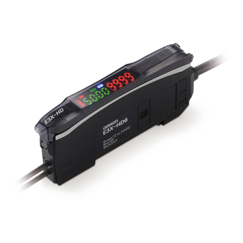
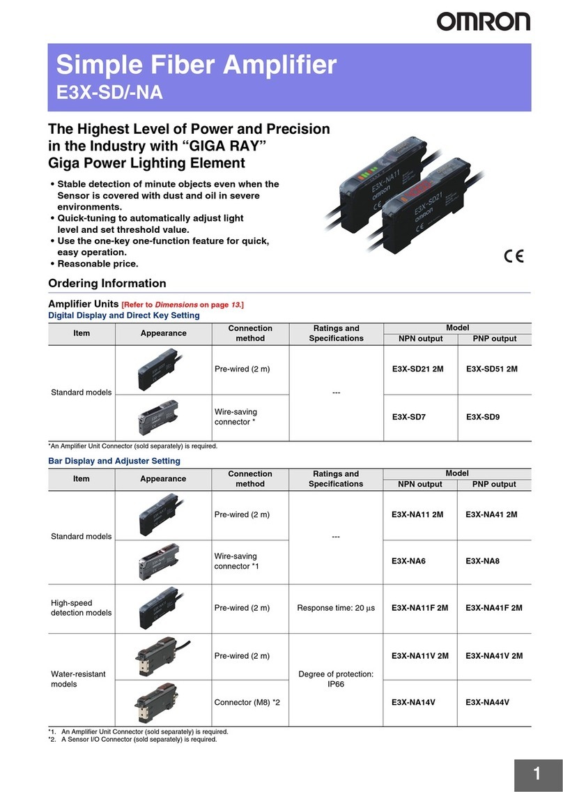
Omron E3X-SD Series User manual

Omron

Omron E3X-SD Series User manual

Omron E3X-NV User manual

Omron

Omron E3X-NV User manual

Omron V640-HAM11 User manual

Omron

Omron V640-HAM11 User manual

Omron E3X-MDA11 User manual

Omron

Omron E3X-MDA11 User manual

Omron E3X-DA-N series User manual

Omron

Omron E3X-DA-N series User manual

Omron E3X-NA - User manual

Omron

Omron E3X-NA - User manual

Omron E3X-CN11 User manual

Omron

Omron E3X-CN11 User manual

Omron E3NX-MA Series User manual

Omron

Omron E3NX-MA Series User manual

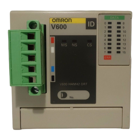
Omron V600-HAM42-DRT User manual

Omron

Omron V600-HAM42-DRT User manual

Omron E3X-NA - User manual

Omron

Omron E3X-NA - User manual

Omron E3X-NA - User manual

Omron

Omron E3X-NA - User manual

Omron E3X-NA F Series User manual

Omron

Omron E3X-NA F Series User manual

Omron E3S User manual

Omron

Omron E3S User manual

Omron K7L-AT50 User manual

Omron

Omron K7L-AT50 User manual

Omron V1000 User manual

Omron

Omron V1000 User manual

Omron V600-HA User manual

Omron

Omron V600-HA User manual

Omron V640 User manual

Omron

Omron V640 User manual

Omron V640-HAM11-ETN User manual

Omron

Omron V640-HAM11-ETN User manual

Omron E3X-DA-S User manual

Omron

Omron E3X-DA-S User manual

Omron V680-HA63 User manual

Omron

Omron V680-HA63 User manual

Omron V640 Series User manual

Omron

Omron V640 Series User manual

Omron E3NC-LA0 User manual

Omron

Omron E3NC-LA0 User manual

Omron V680 -  2 User manual

Omron

Omron V680 - 2 User manual

Omron E3Z-L User manual

Omron

Omron E3Z-L User manual

Popular Amplifier manuals by other brands

Peachtree Audio Grand Integrated user manual

Peachtree Audio

Peachtree Audio Grand Integrated user manual

IKUSI ONE+ SAT Configuration and user's guide

IKUSI

IKUSI ONE+ SAT Configuration and user's guide

Vibe SLICK C10A owner's manual

Vibe

Vibe SLICK C10A owner's manual

Classe Audio CA-3200 owner's manual

Classe Audio

Classe Audio CA-3200 owner's manual

Marantz PM8005 Getting started

Marantz

Marantz PM8005 Getting started

SMSL SA400 manual

SMSL

SMSL SA400 manual

LYNXTechnik D VO 5820 Reference manual

LYNXTechnik

LYNXTechnik D VO 5820 Reference manual

Sansui AU-777 operating instructions

Sansui

Sansui AU-777 operating instructions

Crown XTi 6000 brochure

Crown

Crown XTi 6000 brochure

Audyn AMP-200 user manual

Audyn

Audyn AMP-200 user manual

JL Audio JX360/2 owner's guide

JL Audio

JL Audio JX360/2 owner's guide

NPI ELC-01MX Operating instructions and system description

NPI

NPI ELC-01MX Operating instructions and system description

Pyle PLMRC400X4 user guide

Pyle

Pyle PLMRC400X4 user guide

Inter-m MA-206U Operation manual

Inter-m

Inter-m MA-206U Operation manual

Whyte WATS-1730 instruction manual

Whyte

Whyte WATS-1730 instruction manual

Eden WTB1000 Operation manual

Eden

Eden WTB1000 Operation manual

Revox M30 user manual

Revox

Revox M30 user manual

Unika A Series User instructions

Unika

Unika A Series User instructions

manuals.online logo
manuals.online logoBrands
  • About & Mission
  • Contact us
  • Privacy Policy
  • Terms and Conditions

Copyright 2025 Manuals.Online. All Rights Reserved.