Rane TTM 56 User manual

Manual-1
TTM 56
PERFORMANCE
MIXER
OPERATORS MANUAL
Quick Start
Congratulations! You are the proud owner of an exceptional
performance instrument. Experienced turntablists will find the
TTM 56 comfortable and familiar. The TTM 56 has many unique
features which are mastered quicker if you read the manual.
Right! We know you can’t resist jumping right in, but please read
at least this portion of the manual. It will help you get a good
start.
About the Faders: The Channel Faders and Crossfader are
magnetic, non-contact Faders. This means No travel noise – No
bleed – Ever! The electrical performance of the Faders is unaf-
fected by use. Old habits are hard to break, but you really don’t
have to mess with the Faders. The magnetic Faders in this mixer
are very different from what you are used to. Be sure and read the
Qand Asection on page Manual-10.
Special Features:
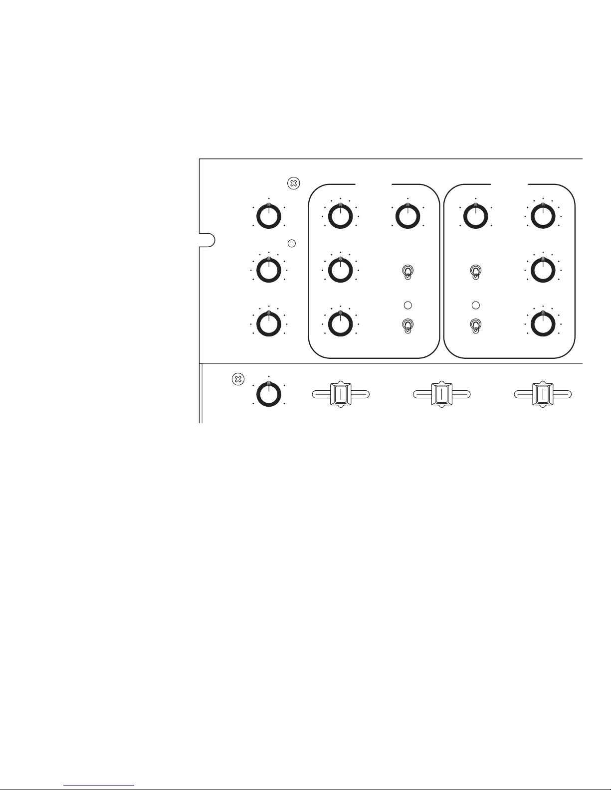
• Channel Fader MODE switches allow selecting two sets of
curves:
MODE 1 gives the familiar stereo fader response.
MODE 2 gives a left/right pan effect.
• Both curves allow continuous adjustment of CONTOUR,
giving smooth blend or fast cut.
• The CHANNEL REVERSE switch allows the left-hand or
right-hand Fader to control PGM 1 or PGM 2.
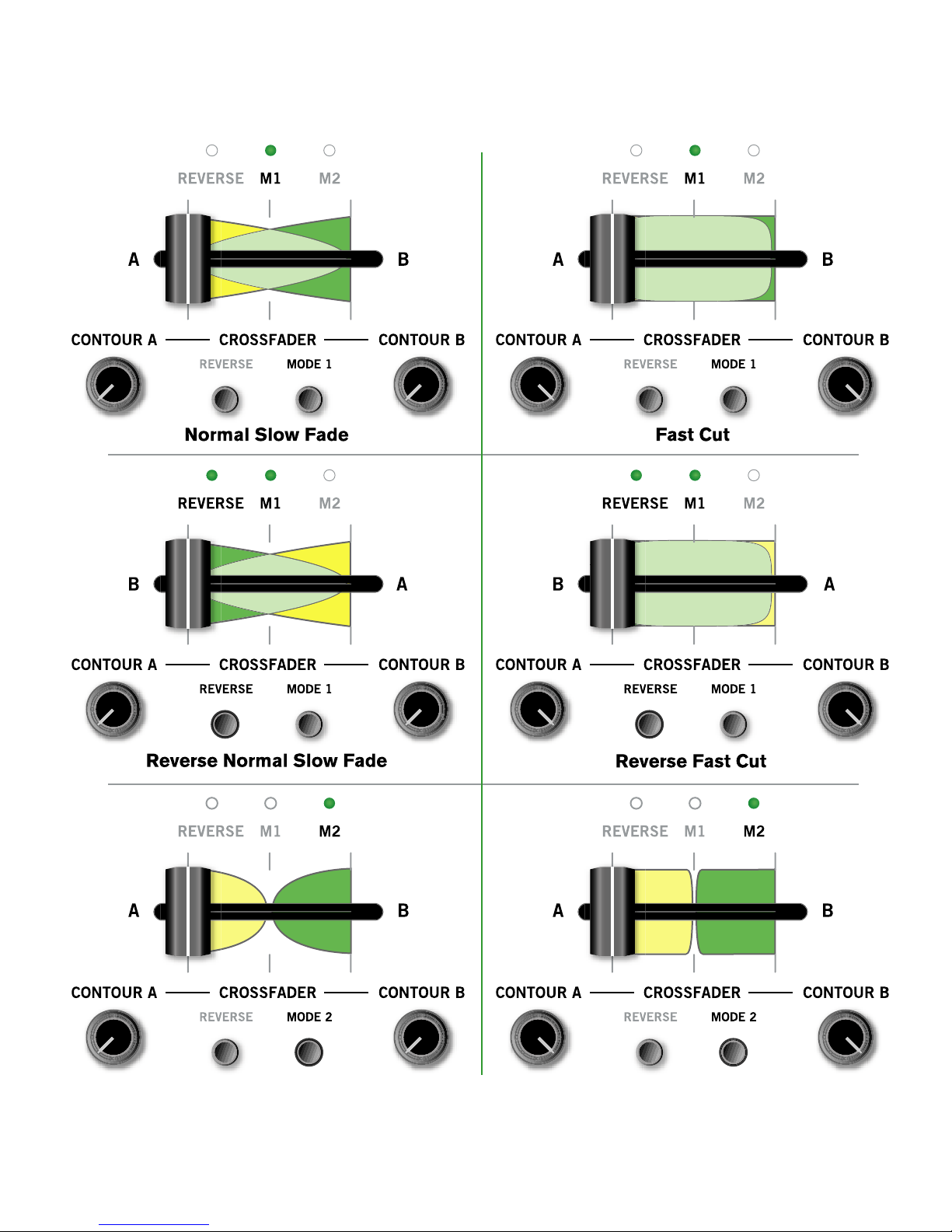
• The CROSSFADER MODE switch allows selecting two sets
of curves:
WEAR PARTS: This product contains the following wear parts subject to the ninety (90) day warranty period described on
page Warranty-1: ST 2 Phono/Line Switch Assembly (2).
MIC
LEVEL
HIGH
LOW
HIGH GAIN GAIN HIGH
MID
EQ EQ
MID AUX OUT
LOW
FlexFX FlexFX
LOW PHONES LEVEL
PGM 2PGM 1
MASTEROL
100
+12-12
+12-12
+6OFF
+6OFF
+6OFF
+6OFF
+6OFF
+6OFF
100
64
28
64
28
100
64
28
100
64
28
100
64
28
100
64
28
AUX IN
+10
+7
+4
+2
0
-4
-2
-7
-10
-20
100
64
28
PERFORMANCE MIXER
FAST
SLOW
TTM 56
L
REVERSE
CONTOUR
REVERSE
MODE 1
MODE 2
CONTOUR
MODE 1
MODE 2
CHANNEL REVERSE
TRANSFORM TRANSFORM
STEREO HOUSE
MONO PGM1 / PGM2
AB
PAN
RDRY WET L
PAN MASTER / CUE
R
PGM 1
CUE
PGM 2
REVERSE MODE 1 MODE 2
FAST
SLOW
MODE 1 gives the familiar PGM 1 to PGM 2 cross-fade response.
MODE 2 gives a center cut response (PGM 1 and PGM 2 are off in the center).
• Independent CONTOUR controls for each side of the Crossfader allow cut on one side and blending on the other (or any
combination).
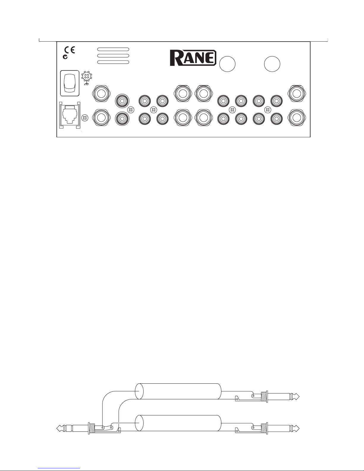
• Auxiliary Inputs and Outputs, with independent level controls, give session mixing ability.
AUX Inputs may be used for drum machine, tape, etc.
AUX Input is after the Crossfader and after the Effects loop.
AUX Outputs may be used for recording, booth monitoring, or a second zone.
AUX Output is the same as the Master Mix.
• FlexFX™allow assignment of PGM 1, PGM 2 or both to the effects loop. The effects loop is post-fader. You get great results
when using the Channel Faders or Crossfader with reverb or other delay effects. WET/DRY pan lets you control how much
effect is in the mix.
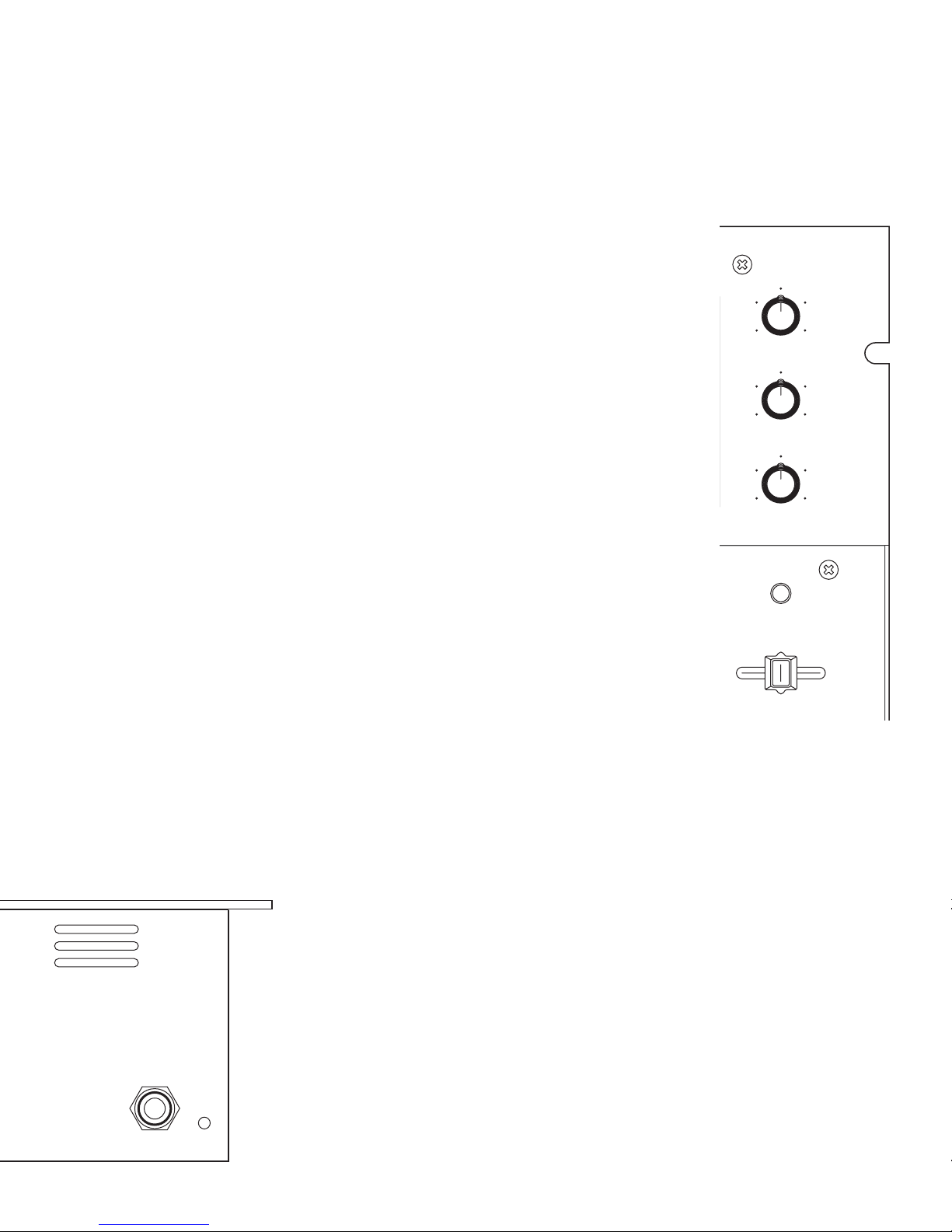
• Three-band Accelerated-Slope™ EQ allows full cut of each band. The EQ engage switch lets you A/B compare or quickly
transform the EQ effect.
• Two, 10-segment meters provide dual-mono-Cue or stereo-Master operation.
• Yes, we included a power switch on the rear.
The flexibility of the TTM 56 Faders can result in some initial confusion. We highly recommend trying one thing at a time.
This helps avoid initial confusion. Make sure the Channel reverse switch is off. Start by changing the Mode and Contour of each
fader, one at a time. See the diagrams on pages Manual-6-7 to understand the fader responses under different settings. Once you
understand the controls, start creating!

Manual-2
Rear Panel Hook-up
Inputs
PGM 1 and PGM 2 each have stereo PHONO and stereo LINE inputs.
PHONO 1 and PHONO 2 inputs are RIAA compensated inputs, for turntables only!
PHONO GND terminals provide independent ground connect points for turntables. It is very important that each turntable have
a very good ground connection to one of these terminals. The thumbscrews will come off if they are over-rotated, so be
careful not to spin them off and lose them.
LINE 1 and LINE 2 inputs are unbalanced line-level inputs with a sensitivity of -10 dBV (max gain).
AUX INPUT may be used with a drum machine, groovebox, sampler, or another mixer’s output for session mix. This Input is
mixed after the Crossfader and Effects loop.
MIC INPUT is a balanced input specifically designed for a dynamic microphone.
Power
POWER connector. This is not a telephone jack! Connect only the Rane RS 1 power supply included with your TTM 56.
The POWER switch is located just above the power connector. You know what to do with this one, but leave it off until every-
thing is connected.
Effects Loops
MIC EFFECTS insert jack is unbalanced. It is wired for TRS, Tip=Send, Ring=Return. This is an independent Effects Loop for
the Mic. There is no engage switch, so the Mic signal is always processed when you have an effects box connected. If you
are connecting to an effects processor with a Send/Return jack, a single TRS cable will work. If your effects processor has
separate Send and Receive jacks, you need a “Y” cable. You can buy a Send/Return cable from your local music store, or you
can make one of your own, as shown below.
FlexFX EFFECTS jacks are unbalanced mono ¼" TS (Tip/Sleeve). This stereo loop is used for output to (send) and input from
(return) an effects processor. The SEND jacks provide the output to your effects processor. The RETURN jacks provide input
for the signal returning from your effects processor. To use with effects insert devices with a single TRS, tip=send,
ring=return jack, you need a “Y” cable, as shown below.
1-CONDUCTOR SHIELDED CABLE
T = SEND
R = RETURN
S = SHIELD
RED RED SEND
RETURN
RED RED
SHIELD SHIELD
SHIELD
Send/Return Cable Wiring
TTM 56
FlexFXMASTER OUT
PHONO GND
EFFECTS
PGM 2AUX PGM 1
MIC
UNBALANCED
CLASS 2
EQUIPMENT
BALANCED
MADE IN U.S.A.
RANE CORP.
U.S. PATENT
PENDING
N108
R
L
L
R
L
OUT IN
RETURN
TIP = SEND
RING = RTRN
R
R
L
R
L
BAL INPUT
LINE 2
SEND
PHONO 2 PHONO 1LINE 1
750mA
POWER

Manual-3
Outputs
AUX OUT may be used for recording, booth monitoring, a second zone, or for connecting to another mixer for session mix.
AUX OUT is the same as the Master Mix with independent Level control.
MASTER OUT includes two sets of stereo outputs: The ¼" TRS jacks provide high current balanced (Tip-Ring-Sleeve) output.
Use the balanced output whenever driving equipment with a balanced input, or when running distances greater than 10 feet (3
meters). Due to the high drive capability and low impedance, never use a mono ¼" Tip/Sleeve (no ring) plug in this jack. Use
the RCA unbalanced outputs for shorter runs connecting to unbalanced devices. See RaneNote 110 if you need to convert
between balanced and unbalanced or run long distances.
Mic Section
MIC LEVEL sets the gain of the
Mic Input. The range of
operation is OFF to +50 dB.
There is no engage switch, so
set the MIC LEVEL to zero
(0) when not in use.
The OL indicator lights 6 dB
before clipping. Adjust MIC
LEVEL so the OL indicator
flashes only when you shout
into the mic.
MIC HIGH and LOW tone
controls provide as much as
12 dB of boost or 12 dB of
cut. These controls have no
effect when the controls are
set to their center detent (12
o'clock).
Program and Aux Input Section
PGM 1 inputs are sent to the left side of the Crossfader. (with the REVERSE switch out)
PGM 2 inputs are sent to the right side of the Crossfader. (with the REVERSE switch out)
AUX INPUT adds another line-level input to the mix. This input comes in after the Crossfader and FlexFX Loop.
GAIN controls adjust the signal level before it gets to the Faders. Set the GAIN controls to indicate an average signal level of +4
on the meter with the Program Faders set to maximum. Don't use the GAIN controls to set the output level...use the MAS-
TER LEVEL control to set the output level. This is a very simple thing, yet makes a huge difference in the performance of
your mixer.
EQ switches engage the 3-band tone controls. EQ switches may be used in conjunction with the Hi, Mid and Low controls as
“kill” switches. Set the rotary controls and flip the switch.
HIGH tone controls affect frequencies above 4 kHz. The range of control is +6 dB to OFF (full kill). The center detent position
leaves this filter inactive. This filter is just above the vocal range, and can make small tonal changes, or eliminate high
frequency signals.
MID tone controls affect frequencies from 300 Hz to 4 kHz (vocal midrange). The range of control is +6 dB to OFF (full kill).
The center detent position leaves this filter inactive. Use for small tonal changes or to cut midrange signals.
LOW tone controls affect frequencies below 300 Hz. The range is +6 dB to OFF (full kill). The center detent position leaves the
filter inactive. These filters influence signals below the vocal range. Use to adjust or eliminate bass beats.
PAN controls adjust the Left and Right balance of PGM 1 and PGM 2. Don't use these excessively for left/right pan effect, they
are not as durable as the Faders. For left/right pan effect, use the Channel Faders in Mode 2.
MIC
LEVEL
HIGH
LOW
HIGH GAIN GAIN HIGH
MID
EQ EQ
MID
LOW
FlexFX FlexFX
LOW
PGM 2PGM 1
OL
100
+12-12
+12-12
+6OFF
+6OFF
+6OFF
+6OFF
+6OFF
+6OFF
100
64
28
64
28
100
64
28
AUX IN
100
64
28
L
PAN
RDRY WET L
PAN
R

Manual-4
+10
+7
+4
+2
0
-4
-2
-7
-10
-20
PERFORMANCE MIXER
FAST
SLOW
TTM 56
REVERSE
CONTOUR
MODE 1
MODE 2
CHANNEL REVERSE
TRANSFORM TRANSFORM
STEREO HOUSE
MONO PGM1 / PGM2
AB
REVERSE MODE 1 MODE 2
CONTOUR A CROSSFADER CONTOUR B
MODEREVERSE
CHANNEL REVERSE switch allows
the left-hand or right-hand Fader to
alternately control PGM 1 or PGM
2. (Don't confuse with the Channel
Fader REVERSE switch, see
below.)
TRANSFORM switches provide two
functions:
• PHONO / LINE source selection for
PGM 1 and 2.
• Quick cut between the used and
unused input.
The switches are easily field
replaceable and may be rotated in
45° increments. See page Manual-
10 for instructions.
Faders
The Channel Faders and Crossfader are magnetic, non-
contact Faders. This means No travel noise – No bleed –
Ever! The electrical performance of the Faders is unaffected
by use. The Channel Faders and Crossfader each have their
own CONTOUR, REVERSE (hamster) and MODE controls.
Magnetic Faders are very different from what you are used
to. Read Maintaining Magnetic Faders on pages Manual 8-
9, and the Magnetic Fader Q & Asection on page Manual-
10.
Channel Fader MODE switch: Channel Fader Mode switches
allow selecting two sets of curves. MODE 1 gives the
familiar stereo fader response. MODE 2 gives left/right pan
effect.
Channel Fader CONTOUR controls allow smooth, continuous
adjustment of contour for both MODE 1 and MODE 2. The
range of control is from SLOW blend to FAST cut.
Channel Fader REVERSE switches change the direction of the
channel Faders. When the reverse switch is engaged, up is
down and down is up (hamster).
CROSSFADER MODE switch allows selecting two sets of
curves for the Crossfader. MODE 1 gives the familiar PGM
1 / PGM 2 crossfade response. MODE 2 gives a center cut
response (PGM 1 and PGM 2 off in the center).
CROSSFADER CONTOUR A & B provide Independent
Contour controls for each side of the Crossfader. This allows
a fast cut on one side and slow blending on the other (or any
combination you choose).
Meters
Meters provide switchable true stereo Master Mix or dual-mono
PGM1 / PGM2 indication of Pre-Program Fader signal
levels. Ten-segment resolution is provided with a one
second, peak hold. Use the meter to set the GAIN controls.
With the Program Fader set to maximum, the input GAIN
should be set to indicate an average level of about +4 dB.

Manual-5
FlexFX Loop
FlexFX switches send PGM 1, PGM 2 or both to the stereo effects loop. The effects loop is post-Fader and post-Crossfader. You
get great results when using the Channel Faders or Crossfader with reverb or other delay effects. The effects loop provides
separate stereo send and return jacks. The green indicators light when FlexFX is engaged.
WET/DRY pan control lets you set the amount of effect in the mix. DRY equals no effect, WET gives maximum effect.
Output Section
MASTER control sets the level for both the unbalanced and balanced Master Outputs.
AUX OUTPUT control sets the level of the Auxiliary Outputs.
Headphone Cueing
The headphone amp in the TTM 56 has a high power output (unlike most you have used before).
There are notable differences…
• The headphone output of the TTM 56 delivers very high volume to your headphones.
• To avoid pain, never put headphones on your head before plugging them in.
• Always start with the PHONES LEVEL turned down, and then turn it up to the desired level.
• Because of the high current and low output impedance, never short one side to ground, or short
left and right together as is possible with mono cup headphones.
• Low power headphone stages typically use large resistors on their outputs, which allow shorting,
but prevent high power. The TTM 56 gives you high power, but does not allow shorting.
MASTER / CUE switch is used to select the headphone monitor source:
• Use MASTER (out) to rehearse your performance. This signal is the same as the MASTER
OUT, but is not affected by the MASTER LEVEL control.
• Use CUE (in) to monitor the Program Input signal before fading in. This signal is not
affected by the Program Faders or Crossfader. Because the Effects Loop is after the Fader, you
will not hear effects in the Cue.
CUE slider allows you to PAN between PGM 1 and PGM 2 in the headphones when the MASTER/CUE switch is depressed.
When the switch is released, this control has no effect.
PHONES LEVEL control sets the output level of the headphone amplifier.
HEADPHONES
PWR
AUX OUT
PHONES LEVEL
MASTER
100
64
28
100
64
28
100
64
28
MASTER / CUE
PGM 1
CUE
PGM 2

Manual-6
FULL ON
OFF
FULL ON
OFF
FULL ON
OFF
FULL ON
OFF
LEFT
RIGHT
LEFT
RIGHT
Channel Fader Response
Channel Fader Response showing effect of Reverse, Mode 1, Mode 2, and Contour controls.

Manual-7
Crossfader Response showing effect of Reverse, Mode 1, Mode 2, and Contour controls.
Crossfader Response

Manual-8
Maintaining Magnetic Faders
There are no electrical contacts to clean!
The Faders in the TTM 56 are designed with materials highly resistant to corrosion and most chemicals. While the Faders will
handle millions of operations, they may become dirty over time. Bad things may be spilled or sprayed into the Faders. In either case,
the Faders are not damaged and the sound quality is unaffected. Cleaning is only required to maintain the feel of the Faders.
The Faders are self-lubricating and with normal use, should not require additional lubrication. If you wish, you can use a light
silicone lubricant rated for use with electrical parts. This will help maintain the feel. If you cannot find a silicone lubricant, you may
use any quality lubricant intended for use in electrical parts containing plastic. Recommended cleaners and lubricants are listed at
the bottom of page Manual-9.
Never use a heavy lubricant or grease. Doing so will not damage the Faders, but can undo the feel. If grease was used, it may be
removed by following the cleaning instructions. See the Recommended Cleaner list below.
Light lubrication is possible with the Lexan plate on. A couple of drops or a short spray are all that is required. Again, make sure the
products you use are suitable for use with electrical parts that contain plastic.
For more effective cleaning and lubrication, follow the directions outlined below:
1. Required Tool: #1 Philips screwdriver
2. Disconnect the power.
3. Remove knobs from controls covered by the Lexan faceplate.
4. Remove the four, 4-40 screws attaching the Lexan faceplate.
5. Remove the Lexan faceplate. See the picture and instructions below. The rails of the fader are now accessible for normal cleaning
and lubrication.
Sensors
Rails
Torsion
Spring
Magnetic Slider Rail Cleaning
a. Move the carrier all the way to one side.
b. Use a soft lint-free cloth to wipe off rails.
c. Add a drop of silicone lubricant (or quick spray from aerosol)
to the center of each rail.
d. Move the carrier back and forth to distribute lubricant.
e. Do not bend torsion spring or touch sensors.

Manual-9
Torsion spring
Sensors
Remove ribbon
Remove
#4 screw
Remove
#4 screw
Mark location before
disconnecting ribbon:
PGM 1
PGM 2
XFADER
Recommended Cleaners & Lubricants
http://www.caig.com/prod.htm
CaiLube X-10S Lubricant
Any generic silicone lubricant intended for use with electronic parts
CaiKleen TRP Cleaner
6. Remove Fader from mixer if more thorough cleaning is required.
7. NOTE: Do not disturb the position of the small sensors at each end of the Fader. If you do, make sure the parts are standing
straight before reinstalling.
8. NOTE: In order to achieve the highest possible accuracy, each magnetic Fader is factory calibrated for the location in which it
was shipped. If you remove the Faders for cleaning, make sure you mark them. This allows you to put them back in the correct
location.
9. Remove the Fader by removing the two #4 screws securing it. Then disconnect the ribbon cable.
10. Sugary liquids spilled into a Fader may be removed by thoroughly rinsing the part in hot water. Make sure the part is clean and
dry before lubricating or reinstalling.
11. Removal of grease or other stubborn debris may require alcohol or contact cleaner. Make sure the part is clean and dry before
lubricating or reinstalling.
12. To reassemble, reverse the disassembly procedure.
13. Problems? Contact Rane Corporation customer service at 425-355-6000.

Manual-10
©Rane Corporation 10802 47th Ave. W., Mukilteo WA 98275-5098 USA TEL (425)355-6000 FAX (425)347-7757 WEB http://www.rane.com
106266
Rotating or Replacing Transform (Phono/Line) Switches
1. Required tool: #1 Philips screwdriver
2. Disconnect the power.
3. Remove knobs from controls covered by the Lexan faceplate.
4. Remove the four 4-40 screws attaching the Lexan faceplate.
5. Remove the two 4-40 switch mounting plate screws.
6. If rotating controls only, go to step 10.
7. Remove the two 2.5 mm screws holding the switch to the plate.
8. Remove the ribbon cable from the switch.
9. Attach the ribbon cable to the new switch.
10. Reattach the switch to the mounting plate.
11. Rotate the switch to the desired location.
12. Reinstall 4-40 screws holding the switch mounting plate.
13. Reinstall the decor faceplate and re-attach control knobs.
Transform
Switch
Important Note
CHASSIS GROUNDING
If your system exhibits excessive hum or buzzing, there is an incompatibility in the grounding configuration between units
somewhere. Here are some things to try:
1. Check that the turntable grounding wires are connected to the PHONO GND posts.
2. Try combinations of lifting grounds on units that are supplied with ground lift switches or links.
3. If your equipment is in a rack, verify that all chassis are tied to a good earth ground, either through the line cord grounding
pin or the rack screws to another grounded chassis, or tied to the ground screw located next to the POWER switch.
4. This unit’s outboard power supply does not ground the chassis through the line cord. Make sure that this unit is grounded
either to another chassis which is earth grounded, or directly to the grounding screw on an AC outlet cover by means of a wire
connected to a screw on the chassis with a star washer to guarantee proper contact.
Please refer to the RaneNote, “Sound System Interconnection” (supplied with this manual and available on our website) for
further information on system grounding.
Magnetic Fader Q and A
Q: Will I damage the faders if I spray them with bad stuff or spill bad things in them?
A: No. The Faders in the TTM 56 are designed with materials highly resistant to corrosion and most chemicals. There are no
electrical contacts to clean or damage. While bad things may change the feel of the Faders, bad things will not affect the
sound. To clean Faders that have had a bad thing put in them, follow the simple instructions on page Manual-8.
Q: Can I install magnetic Faders in a TTM 54, TTM 52 or any other mixer?
A: Sorry. The connectors may be similar, but the circuits are very different. Connecting the Faders to anything other than the
intended cable in the TTM 56 could permanently damage them.
Q: Can I install other Faders in my TTM 56?
A: No. The cable connections are specially designed for Rane magnetic Faders.
Q: Can I install a different magnetic Fader in my mixer or swap the position of my Faders?
A: No. In order to achieve the highest possible accuracy, each magnetic Fader is factory calibrated for the location in which it
was shipped. For information about replacement or calibration, contact Rane Customer Service. If you remove the Faders for
cleaning, make sure you mark them. This allows you to put them back in the same location.
Other manuals for TTM 56
2
Table of contents
Other Rane Music Mixer manuals