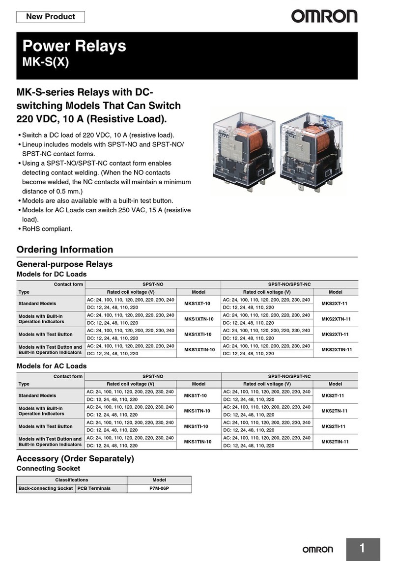
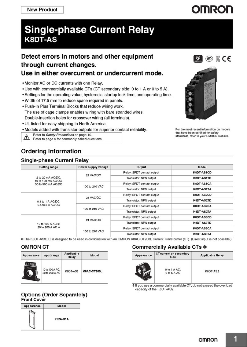
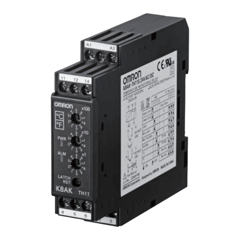
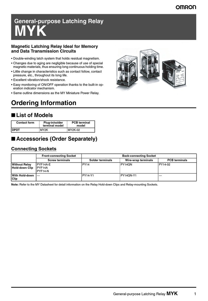
Omron F3SP-T01 User manual

CSM_F3SP-T01_DS_E_3_1
1
Safety Terminal Relays (for F3SJ-A@@@@P@@)
F3SP-T01
Simplifies wiring from Safety Light
Curtains to the Safety Relay outputs.
• Simplifies wiring inside the panel and helps prevent incorrect
wiring.
• Terminals are numbered to make it easy to check terminal
connections.
• Replacement of relays is easy, improving maintainability.
• Screw-less clamp terminals eliminate the need for extra
tightening.
• The Support Software can be connected, enabling on-site
adjustment of Light Curtains.
Ordering Information
Safety Terminal Relays
Optional Accessories (Sold Separately)
Specifications (Refer to Instruction Manual for details.)
Ratings
Power supply
Contacts
Characteristics
Durability
As of June 2009
Be sure to read the “Safety Precautions” on page 8 and
the “Precautions for All Safety Sensors” .
Type Applicable models Model
Safety Terminal Relay F3SJ-A@@@@P@@ F3SP-T01
Type Model
Cable for connecting Support Software (cable length: 1.5 m) E39-Z12-1
Replacement Relay G7SA-3A1B
Rated voltage 24 VDC+10%/−15%
Rated power
consumption
DC 1.7 W max. (not including sensor's power
consumption)
Rated load 250 VAC 3 A, resistive load
30 VDC 3 A, resistive load
Rated current 3 A
Applicable Relays G7SA-3A1B: 24 VDC
Operation time 100 ms max.
(not including sensor's response time)
Response time 10 ms max.
(not including sensor's response time)
Vibration
resistance
10 to 55 to 10 Hz
Single amplitude: 0.35 mm
(Double amplitude: 0.7 mm)
Shock resistance Destruction: 300 m/s2, Malfunction: 100 m/s2
Ambient operating
temperature −10 to 55°C
Ambient operating
humidity 35 to 85%
Weight Approx. 215 g
Electrical
durability
100,000 operations min.
Rated load
Switching frequency: 1,800 operations/h
Mechanical
durability
5,000,000 operations min.
Switching frequency: 7,200 operations/h

F3SP-T01
2
Connections
Internal Circuit Diagrams
Wiring Diagrams
Relay contact output terminal
K1
K2
Modular Connector
I/O terminals
NC L1
MA0
L8
MB0 MA1 MA2 MB1 MB2
L1 L3 L4 D1
K2 K1
D3 D4
TST RST
V V NC V
FB1
VVVVL2L8L5D2D8D5VV
G G NC G
FB2
G G G G L7 G L6 D7 G D6 G G
AUX
V
G
1234
13 14 23 24 NC NC
23
24
33
34
43
44
43
44
11
12
11
12
Receiver
Emitter
L1: Muting input 1 (White)
L2: 24 V (Brown)
L3: Test input (Green)
L4: Reset input (Yellow)
L5: Communications line + (Gray):
L6: Communications line −(Pink)
L7: 0 V (Blue)
L8: Muting input 2 (Red):
G: Shield
D1: Control output 2 (White)
D2: 24 V (Brown)
D3: Control output 1 (Green)
D4: Auxiliary output (Yellow)
D5: Communications line + (Gray)
D6: Communications line −(Pink)
D7: 0 V (Blue)
D8: External device monitoring input (Red)
G: Shield

F3SP-T01
3
Wiring Example
The following example is for when two muting sensors are connected in the auto reset mode, and the
external device monitoring function is enabled.
The following example is for when two muting sensors are connected in auto reset mode, and the
external device monitoring function is disabled.
24 V
0 V
Muting output
24 V
0 V
Muting output Muting Sensor 1
Muting Sensor 2
NC L1
MA0
L8
MB0 MA1 MA2 MB1 MB2
L1 L3 L4 D1 D3 D4
TST RST
V V NC V FB1 V V V V L2 L8 L5 D2 D8 D5 V V
GG
13 14 23 24 NC NC
NC G FB2 G G G G L7 G L6 D7 G D6 G G
AUX
V
G
KM1
M
KM2
KM1
24 V DC
KM2
KM2
F2F1
KM1
L1
(R)
L2
(S)
L3
(T)
S1: External test switch
KM1, KM2: Magnet contactor
M: 3-phase motor
F1, F2: Fuse
PLC
S1
Receiver
Emitter
24 V (Brown)
Muting input 1 (White)
0 V (Blue)
Muting input 2 (Red)
Test input (Green)
Shield
Communications line + (Gray)
Reset input (Yellow)
Communications line – (Pink)
24 V (Brown)
Control output 2 (White)
0 V (Blue)
External device monitoring input (Red)
Control output 1 (Green)
Shield
Communications line + (Gray)
Auxiliary output (Yellow)
Communications line – (Pink)
24 V
0 V
Muting output
24 V
0 V
Muting output
24 V
0 V
Muting output
24 V
0 V
Muting output
L1
MA0
L8
MB0 MA1 MA2 MB1 MB2
VVVV
GGGG
Muting Sensor 1
Muting Sensor 2
Muting Sensor 3
Muting Sensor 4
Note: 1. To use the muting function, a
Muting Keycap (F39-CN6)
must be mounted to the F3SJ.
2. If a lockout reset is required,
connect a switch between RST
and V.
Connecting Four Muting Sensors
Note: If you are connecting four muting
sensors, connect the sensor outputs to
MA1, MA2, MB1, and MB2. Also
short-circuit MA0 to L1, and MB0 to L8.
24 V
0 V
24 V
0 V
KM1
M
KM2
13 14 23 24 NC NC
24 V DC
KM2
F2F1
KM1
L1
(R)
L2
(S)
L3
(T)
NC L1
MA0
L8
MB0 MA1 MA2 MB1 MB2
L1 L3 L4 D1 D3 D4
TST RST
V V NC V FB1 V V V V L2 L8 L5 D2 D8 D5 V V
G G NC G FB2 G G G G L7 G L6 D7 G D6 G G
AUX
V
G
PLC
S1
Muting output
Muting output Muting Sensor 1
Muting Sensor 2
S1: External test switch
KM1, KM2: Magnet contactor
M: 3-phase motor
F1, F2: Fuse
Receiver
Emitter
24 V (Brown)
Muting input 1 (White)
0 V (Blue)
Muting input 2 (Red)
Test input (Green)
Shield
Communications line + (Gray)
Reset input (Yellow)
Communications line – (Pink)
24 V (Brown)
Control output 2 (White)
0 V (Blue)
External device monitoring input (Red)
Control output 1 (Green)
Shield
Communications line + (Gray)
Auxiliary output (Yellow)
Communications line – (Pink)
Note: 1. To use the muting function, a
Muting Keycap (F39-CN6)
must be mounted to the F3SJ.
2. If a lockout reset is required,
connect a switch between RST
and V.
24 V
0 V
24 V
0 V
24 V
0 V
24 V
0 V
L1
MA0
L8
MB0 MA1 MA2 MB1 MB2
VVVV
GGGG
Muting output
Muting output
Muting output
Muting output
Muting Sensor 1
Muting Sensor 2
Muting Sensor 3
Muting Sensor 4
Connecting Four Muting Sensors
Note: If you are connecting four muting
sensors, connect the sensor outputs to
MA1, MA2, MB1, and MB2. Also
short-circuit MA0 to L1, and MB0 to L8.

4
F3SP-T01
The following example is for when no muting sensors are connected in the auto reset mode, and the
external device monitoring function is enabled.
The following example is for when no muting sensors are connected in the auto rest mode, and the
external device monitoring function is disabled.
13 14 23 24 NC NC KM1
M
KM2
KM1
24 V DC
KM2
KM2
F2F1
KM1
L1
(R)
L2
(S)
L3
(T)
S1: External test switch
KM1, KM2: Magnet contactor
M: 3-phase motor
F1, F2: Fuse
NC L1
MA0
L8
MB0 MA1 MA2 MB1 MB2
L1 L3 L4 D1 D3 D4
TST RST
V V NC V FB1 V V V V L2 L8 L5 D2 D8 D5 V V
G G NC G FB2 G G G G L7 G L6 D7 G D6 G G
AUX
V
G
PLC
S1
Receiver
Emitter
24 V (Brown)
Muting input 1 (White)
0 V (Blue)
Muting input 2 (Red)
Test input (Green)
Shield
Communications line + (Gray)
Reset input (Yellow)
Communications line – (Pink)
24 V (Brown)
Control output 2 (White)
0 V (Blue)
External device monitoring input (Red)
Control output 1 (Green)
Shield
Communications line + (Gray)
Auxiliary output (Yellow)
Communications line – (Pink)
Note: If a lockout reset is required, connect a switch between RST and V.
KM1
M
KM2
13 14 23 24 NC NC
24 V DC
KM2
F2F1
KM1
L1
(R)
L2
(S)
L3
(T)
S1: External test switch
KM1, KM2: Magnet contactor
M: 3-phase motor
F1, F2: Fuse
NC L1
MA0
L8
MB0 MA1 MA2 MB1 MB2
L1 L3 L4 D1 D3 D4
TST RST
V V NC V FB1 V V V V L2 L8 L5 D2 D8 D5 V V
G G NC G FB2 G G G G L7 G L6 D7 G D6 G G
AUX
V
G
PLC
S1
Receiver
Emitter
24 V (Brown)
Muting input 1 (White)
0 V (Blue)
Muting input 2 (Red)
Test input (Green)
Shield
Communications line + (Gray)
Reset input (Yellow)
Communications line – (Pink)
24 V (Brown)
Control output 2 (White)
0 V (Blue)
External device monitoring input (Red)
Control output 1 (Green)
Shield
Communications line + (Gray)
Auxiliary output (Yellow)
Communications line – (Pink)
Note: If a lockout reset is required, connect a switch between RST and V.

F3SP-T01
5
The following example is for when two muting sensors are connected in the manual reset mode, and
the external device monitoring function is enabled.
The following example is for when two muting sensors are connected in manual reset mode, and the
external device monitoring function is disabled.
NC L1
MA0
L8
MB0 MA1 MA2 MB1 MB2
L1 L3 L4 D1 D3 D4
TST RST
V V NC V FB1 V V V V L2 L8 L5 D2 D8 D5 V V
G G NC G FB2 G G G G L7 G L6 D7 G D6 G G
AUX
V
G
13 14 23 24 NC NC
KM1
M
KM2
KM1
24 V DC
KM2
KM2
F2F1
KM1
L1
(R)
L2
(S)
L3
(T)
PLC
24 V
0 V
24 V
0 V
S1
S2
Connecting
Cable
E39-Z12-1
Computer Tool
for F3SJ
F39-GWUM
Muting output
Muting output Muting Sensor 1
Muting Sensor 2
S1: External test switch
S2: Interlock/lockout reset switch
KM1, KM2: Magnet contactor
M: 3-phase motor
F1, F2: Fuse
Receiver
Emitter
24 V (Brown)
Muting input 1 (White)
0 V (Blue)
Muting input 2 (Red)
Test input (Green)
Shield
Communications line + (Gray)
Reset input (Yellow)
Communications line – (Pink)
24 V (Brown)
Control output 2 (White)
0 V (Blue)
External device monitoring input (Red)
Control output 1 (Green)
Shield
Communications line + (Gray)
Auxiliary output (Yellow)
Communications line – (Pink)
Note: 1. To use the muting function, a
Keycap for Muting (F39-CN6)
must be mounted to the F3SJ.
2. To use the manual reset mode
while using the muting function,
the F3SJ setting must be
changed using the Support
Software.
3. It is recommended that you use
the E39-Z12-1 as the modular
cable to connect the Support
Software.
L1
MA0
L8
MB0 MA1 MA2 MB1 MB2
VVVV
GGGG
24 V
0 V
24 V
0 V
24 V
0 V
24 V
0 V
Muting output
Muting output
Muting output
Muting output
Muting Sensor 1
Muting Sensor 2
Muting Sensor 3
Muting Sensor 4
Connecting Four Muting Sensors
Note: If you are connecting four muting sensors,
connect the sensor outputs to MA1, MA2,
MB1, and MB2. Also short-circuit MA0 to
L1, and MB0 to L8.
NC L1
MA0
L8
MB0 MA1 MA2 MB1 MB2
L1 L3 L4 D1 D3 D4
TST RST
V V NC V FB1 V V V V L2 L8 L5 D2 D8 D5 V V
G G NC G FB2 G G G G L7 G L6 D7 G D6 G G
AUX
V
G
13 14 23 24 NC NC
KM1
M
KM2
24 V DC
KM2
F2F1
KM1
L1
(R)
L2
(S)
L3
(T)
PLC
24 V
0 V
24 V
0 V
S1
S2
Muting output
Muting output Muting Sensor 1
Muting Sensor 2
S1: External test switch
S2: Interlock/lockout reset switch
KM1, KM2: Magnet contactor
M: 3-phase motor
F1, F2: Fuse
Receiver
Emitter
24 V (Brown)
Muting input 1 (White)
0 V (Blue)
Muting input 2 (Red)
Test input (Green)
Shield
Communications line + (Gray)
Reset input (Yellow)
Communications line – (Pink)
24 V (Brown)
Control output 2 (White)
0 V (Blue)
External device monitoring input (Red)
Control output 1 (Green)
Shield
Communications line + (Gray)
Auxiliary output (Yellow)
Communications line – (Pink)
Connecting
Cable
E39-Z12-1
Computer Tool
for F3SJ
F39-GWUM
Note: 1. To use the muting function, a Keycap
for Muting (F39-CN6) must be
mounted to the F3SJ.
2. To use the manual reset mode while
using the muting function, the F3SJ
setting must be changed using the
Support Software.
3. It is recommended that you use the
E39-Z12-1 as the modular cable to
connect the Support Software.
L1
MA0
L8
MB0 MA1 MA2 MB1 MB2
VVVV
GGGG
24 V
0 V
24 V
0 V
24 V
0 V
24 V
0 V
Muting output
Muting output
Muting output
Muting output
Muting Sensor 1
Muting Sensor 2
Muting Sensor 3
Muting Sensor 4
Connecting Four Muting Sensors
Note: If you are connecting four muting
sensors, connect the sensor outputs to
MA1, MA2, MB1, and MB2. Also
short-circuit MA0 to L1, and MB0 to L8.

6
F3SP-T01
The following example is for when no muting sensors are connected in the manual reset mode, and the
external device monitoring function is enabled.
The following example is for when no muting sensors are connected in the manual rest mode, and the
external device monitoring function is disabled.
NC L1
MA0
L8
MB0 MA1 MA2 MB1 MB2
L1 L3 L4 D1 D3 D4
TST RST
V V NC V FB1 V V V V L2 L8 L5 D2 D8 D5 V V
GG
13 14 23 24 NC NC
NC G FB2 G G G G L7 G L6 D7 G D6 G G
AUX
V
G
KM1
M
KM2
KM1
24 V DC
KM2
KM2
F2F1
KM1
L1
(R)
L2
(S)
L3
(T)
PLC
S1
S2
S1: External test switch
S2: Interlock/lockout reset switch
KM1, KM2: Magnet contactor
M: 3-phase motor
F1, F2: Fuse
Receiver
Emitter
24 V (Brown)
Muting input 1 (White)
0 V (Blue)
Muting input 2 (Red)
Test input (Green)
Shield
Communications line + (Gray)
Reset input (Yellow)
Communications line – (Pink)
24 V (Brown)
Control output 2 (White)
0 V (Blue)
External device monitoring input (Red)
Control output 1 (Green)
Shield
Communications line + (Gray)
Auxiliary output (Yellow)
Communications line – (Pink)
NC L1
MA0
L8
MB0 MA1 MA2 MB1 MB2
L1 L3 L4 D1 D3 D4
TST RST
V V NC V FB1 V V V V L2 L8 L5 D2 D8 D5 V V
G G NC G FB2 G G G G L7 G L6 D7 G D6 G G
AUX
V
G
KM1
M
KM2
13 14 23 24 NC NC
24 V DC
KM2
F2F1
KM1
L1
(R)
L2
(S)
L3
(T)
PLC
S1
S1: External test switch
S2: Interlock/lockout reset switch
KM1, KM2: Magnet contactor
M: 3-phase motor
F1, F2: Fuse
S2
Receiver
Emitter
24 V (Brown)
Muting input 1 (White)
0 V (Blue)
Muting input 2 (Red)
Test input (Green)
Shield
Communications line + (Gray)
Reset input (Yellow)
Communications line – (Pink)
24 V (Brown)
Control output 2 (White)
0 V (Blue)
External device monitoring input (Red)
Control output 1 (Green)
Shield
Communications line + (Gray)
Auxiliary output (Yellow)
Communications line – (Pink)

7
F3SP-T01
Dimensions (Unit: mm)
Relay contact output terminals
180
Two, 4.2 dia. holes
55
(169)
51
(40)
I/O terminals
Status indicators (LEDs)
From left to right: PWR, RY1 (K1), RY2 (K2), TEST, RESET, and AUX.
G7SA-3A1B (K1)
G7SA-3A1B (K2)
Modular Connector
for Light Curtain
Support Software
F3SP-T01

8
F3SP-T01
Safety Precautions
!WARNING
Do not operate the product in atmospheres containing
flammable or explosive gas. Arcs or heating of relays
during switching may cause fire or explosion.
Do not use a load that exceeds the contact ratings or
switching capacity. Doing so may cause the product to fail
to perform its specified functions, causing insulation failure,
contact welding, or contact failure. It may also cause
damage to the F3SP-T01 or burning.
The service life will depend on the switching conditions. Be
sure to check the actual operating conditions using the
actual devices, and make sure that the number of switching
operations will not cause performance problems. If you
continue to use the device with deteriorated performance, it may
result in breakdown of insulation between circuits, or cause burning of
the product.
Handle with Care
Do not drop the product or expose it to excessive vibration or shock.
Doing so may prevent it from functioning properly.
Adhesion of Solvent
Do not allow solvents, such as alcohol, thinner, trichloroethane, or
gasoline, to come into contact with the product. Such solvents may
make the markings illegible and cause deterioration of parts.
Installation Location
Do not install or store the product in the following locations. Doing so
may result in product failure or malfunction.
•Locations subject to direct sunlight
•Locations subject to temperatures outside the range −10 to 55°C
•Locations subject to humidity levels outside the range 35% to 85%
•Locations subject to condensation due to extreme temperature
changes
•Locations subject to atmospheric pressures outside the range 86
to 106 kPa
•Locations subject to corrosive or flammable gases
•Locations subject to shock or vibration in excess of the product
ratings
•Locations subject to exposure to water, oil, or chemicals
•Locations subject to dust (including iron dust) or salts
Take appropriate and sufficient countermeasures when using the
product in the following locations.
•Locations subject to static electricity or other forms of noise
•Locations subject to possible exposure to radioactivity
•Locations close to power supply lines
Installation
•Do not use products that have been dropped or have its internal
parts disassembled. Specified characteristics may not be
achieved, and may cause damage to the product or burning.
•If the products are installed side-by-side, the rated current is 1 A.
Do not exceed 1 A.
•Use the F3SP-T01 in an enclosure that provides at least IP54
degree of protection.
Installation and Wiring
•Use the following electrical wiring for external I/O devices.
Compatible Ferrules
•Use ferrules that meet the following standards for length and width.
If the standards are not met, connection may fail, or the ferrules
may not be able to be plugged in and out of the terminals.
•Ferrule Dimensions (for Power Supply Terminal of F3SP-T01)
•Recommended Ferrule and Crimping Tool
Precautions for Safe Use
Solid wire 0.2 to 1.3 mm2AWG24 to 16
Flexible
wires
1.3 to 2.0 mm2, AWG16 to 14
If flexible wires are used, terminate the wires with
insulated ferrules (DIN 46228-4 compatible type)
before connecting them.
Square
Ferrules
Dimension A 1.0 to 2.3 The cross-sectional
area after crimping
must be less than
4.8 mm2.
Dimension B 0.8 to 2.65
Cylindrical
Ferrules Dimension C 0.8 dia. to 2.3 dia.
Type of
ferrule
Manufacturer
Size Model
Recommended
crimping tool
Square
Ferrules
Phoenix
Contact
AWG24 AI0.25-8YE
UD6
ZA3
AWG22 AI0.34-8TQ
AWG20 AI0.5-10WH
AI0.5-8WH
AWG18 AI0.75-10GY
AI0.75-8GY
AWG16 AI1.5-10BK
AWG14 AI2.5-10BU
Weidmuller
AWG24 H0.25/12
PZ6 roto
AWG22 H0.34/12
AWG20 H0.5/16
H0.5/14
AWG18 H0.75/16
H0.75/14
AWG16 H1.5/16
Cylindrical
Ferrules Nichifu
AWG22
TGV TC-1.25-11T
TGN TC-1.25-11T
NH11
NH32
NH65
AWG20
AWG18
AWG16
B
C dia.
Square Ferrules Cylindrical Ferrules
A

F3SP-T01
9
•Apply the specified voltages to the input terminals. Applying an
inappropriate voltage may prevent specified functions from
operating properly, which may cause damage to the product or
burning.
•Disconnect the power supply before wiring.
•Check the condition of the emitter and receiver before connecting
them.
•You cannot use the product if the positive side is connected to
ground.
•NC terminals have no function. Do not connect them.
Wiring the Terminal Block
•Insert the wires using the following procedure.
Flexible wires: (1) Use a flat-blade screwdriver to push in the lever
and (2) insert the wire.
Solid wires or ferrules: Insert the wire into the wire hole and push
all the way to the back. (Operating the lever is not required.)
•Remove the wires using the following procedure (same for flexible
wires, solid wires, and ferrules).
(1) Use a flat-blade screwdriver to push in the lever and (3) pull out
the wire.
•Use a flat-blade screwdriver that has the same thickness from tip
to base and is within the following standards.
Mounting to and Removing from DIN Track
•To mount the product to a DIN Track, release the slider lock, place
the product on the DIN track, and then lock the slider.
•After using the slider lock, make sure that the lock is engaged on
the DIN Track.
•To dismount the product from the DIN Track, place the driver in the
slider section, release the lock, and then remove the product from
the DIN Track.
•Secure both ends of the Safety
Terminal Relays with End Plates.
The following products are sold
separately.
Selecting the Power Supply
•Use the rated power supply voltage. Do not use power supplies
with large ripple component or intermittent irregular voltages.
•To meet IEC 61496-1 and UL 508 safety standards and to prevent
electrical shock, make sure that the power supply and load satisfy
the requirements outlined in the sensor's user manual.
Periodic Checks and Maintenance
•Do not attempt to disassemble, repair, or modify the product.
•Make sure that the power supply is turned OFF before replacing
parts.
Disposal
•Exercise caution to prevent injury when disassembling the F3SP-
T01.
Durability of Contact Outputs
The durability of the contact outputs on Safety Terminal Relays varies
considerably depending on switching conditions. Always confirm the
usage conditions by testing the Safety Terminal Relay in an actual
application, and use the Safety Terminal Relay only for the number of
switching operations that its performance allows. Restarting may not
be possible if the switching capacity is exceeded. If this occurs,
replace the relevant relays immediately. If a Safety Terminal Relay is
used after performance has deteriorated, it may result in reduced
safety.
(3) (2)
(1)
Lever
Insert wire here
Side
view
Front
view
DE
We recommend the following flat-blade
screwdrivers for inserting wires.
Recommended Screwdrivers
Dimension D 0.3 to 0.8
Dimension E 2.9 to 3.6
Model
XW4Z-00B
XW4Z-00C
DIN Tracks PFP-50N
PFP-100N
End Plate PFP-M
Precautions for Correct Use
Screwdriver
Slider

Read and Understand This Catalog
Please read and understand this catalog before purchasing the products. Please consult your OMRON representative if you have any questions or
comments.
Warranty and Limitations of Liability
WARRANTY
OMRON's exclusive warranty is that the products are free from defects in materials and workmanship for a period of one year (or other period if specified)
from date of sale by OMRON.
OMRON MAKES NO WARRANTY OR REPRESENTATION, EXPRESS OR IMPLIED, REGARDING NON-INFRINGEMENT, MERCHANTABILITY, OR
FITNESS FOR PARTICULAR PURPOSE OF THE PRODUCTS. ANY BUYER OR USERACKNOWLEDGES THAT THE BUYER OR USERALONE HAS
DETERMINED THAT THE PRODUCTS WILL SUITABLY MEETTHE REQUIREMENTS OF THEIR INTENDED USE. OMRON DISCLAIMSALL OTHER
WARRANTIES, EXPRESS OR IMPLIED.
LIMITATIONS OF LIABILITY
OMRON SHALL NOT BE RESPONSIBLE FOR SPECIAL, INDIRECT, OR CONSEQUENTIAL DAMAGES, LOSS OF PROFITS OR COMMERCIAL LOSS
IN ANY WAY CONNECTED WITH THE PRODUCTS, WHETHER SUCH CLAIM IS BASED ON CONTRACT, WARRANTY, NEGLIGENCE, OR STRICT
LIABILITY.
In no event shall the responsibility of OMRON for any act exceed the individual price of the product on which liability is asserted.
IN NO EVENT SHALL OMRON BE RESPONSIBLE FOR WARRANTY, REPAIR, OR OTHER CLAIMS REGARDING THE PRODUCTS UNLESS
OMRON'S ANALYSIS CONFIRMS THAT THE PRODUCTS WERE PROPERLY HANDLED, STORED, INSTALLED,AND MAINTAINED AND NOT
SUBJECTTO CONTAMINATION, ABUSE, MISUSE, OR INAPPROPRIATE MODIFICATION OR REPAIR.
Application Considerations
SUITABILITYFOR USE
OMRON shall not be responsible for conformity with any standards, codes, or regulations that apply to the combination of products in the customer's
application or use of the products.
At the customer's request, OMRON will provide applicable third party certification documents identifying ratings and limitations of use that apply to the
products. This information by itself is not sufficient for a complete determination of the suitability of the products in combination with the end product,
machine, system, or other application or use.
The following are some examples of applications for which particular attention must be given. This is not intended to be an exhaustive list of all possible
uses of the products, nor is it intended to imply that the uses listed may be suitable for the products:
•
Outdoor use, uses involving potential chemical contamination or electrical interference, or conditions or uses not described in this catalog.
•
Nuclear energy control systems, combustion systems, railroad systems, aviation systems, medical equipment, amusement machines, vehicles,
safety equipment, and installations subject to separate industry or government regulations.
•
Systems, machines, and equipment that could present a risk to life or property.
Please know and observe all prohibitions of use applicable to the products.
NEVER USE THE PRODUCTS FORANAPPLICATION INVOLVING SERIOUS RISK TO LIFE OR PROPERTY WITHOUT ENSURING THAT THE
SYSTEMAS A WHOLE HAS BEEN DESIGNED TO ADDRESS THE RISKS,AND THAT THE OMRON PRODUCTSARE PROPERLY RATED AND
INSTALLED FOR THE INTENDED USE WITHIN THE OVERALL EQUIPMENT OR SYSTEM.
PROGRAMMABLE PRODUCTS
OMRON shall not be responsible for the user's programming of a programmable product, or any consequence thereof.
Disclaimers
CHANGE IN SPECIFICATIONS
Product specifications and accessories may be changed at any time based on improvements and other reasons.
It is our practice to change model numbers when published ratings or features are changed, or when significant construction changes are made.
However, some specifications of the products may be changed without any notice. When in doubt, special model numbers may be assigned to fix or
establish key specifications for your application on your request. Please consult with your OMRON representative at any time to confirm actual
specifications of purchased products.
DIMENSIONSAND WEIGHTS
Dimensions and weights are nominal and are not to be used for manufacturing purposes, even when tolerances are shown.
PERFORMANCE DATA
Performance data given in this catalog is provided as a guide for the user in determining suitability and does not constitute a warranty. It may represent the
result of OMRON’s test conditions, and the users must correlate it to actual application requirements. Actual performance is subject to the OMRON
Warranty and Limitations of Liability.
ERRORS AND OMISSIONS
The information in this document has been carefully checked and is believed to be accurate; however, no responsibility is assumed for clerical,
typographical, or proofreading errors, or omissions.
2009.9
In the interest of product improvement, specifications are subject to change without notice.
OMRON Corporation
Industrial Automation Company
http://www.ia.omron.com/
(c)Copyright OMRON Corporation 2009 All Right Reserved.
Table of contents
Other Omron Relay manuals

Omron
Omron G9SA-501 User manual

Omron
Omron ZEN User manual

Omron
Omron G9SE-201 User manual

Omron
Omron MYK User manual

Omron
Omron G3PA-450B-VD-2 User manual

Omron
Omron K8AK-VW2 24 VAC/DC User manual

Omron
Omron K8DT-VS Series User manual

Omron
Omron K8AB-TH User manual

Omron
Omron K8AB-VS Series User manual

Omron
Omron K6EL User manual