Omron K8AB-PH User manual

Cat. No. N145-E1-01 Phase-sequence Phase-loss Relay K8AB-PH 1
Phase-sequence Phase-loss Relay
K8AB-PH
Ideal for phase sequence and phase loss
monitoring for industrial facilities and
equipment.
• Simultaneously monitor phase sequence and phase loss for
three-phase 3-wire power supplies.
• One SPDT output relay, 6 A at 250 VAC (resistive load).
• Relay warning status easily monitoring using LED indicator.
• Easy wiring with ferrules
2 ×2.5 mm2solid or 2 ×1.5 mm2standard ferrules.
• CE mark compliance certified by third party.
UL certification pending.
Model Number Structure
■Model Number Legend
1. Basic Model
K8AB: Measuring and Monitoring Relays
2. Functions
PH: Phase-sequence Phase-loss Relay
3. Rated Input Voltage
1: 200 to 500 VAC
123
K8AB-@@

2Phase-sequence Phase-loss Relay K8AB-PH Cat. No. N145-E1-01
Ordering Information
■List of Models
Note: The power supply is shared with the rated input voltage.
Ratings and Specifications
■Ratings
Phase-sequence Phase-loss Relay Rated input voltage (See note.) Model
200 to 500 VAC K8AB-PH1
Rated input voltage Non-isolated 200 to 500 VAC (15 VA)
Phase sequence, phase loss operating time 0.1 s max. (value when rated operating voltage changes quickly from 0% to 100%)
(Relays are normally ON and turn OFF for phase sequence or loss phase errors.)
Resetting method Automatic reset
Input frequency 45 to 65 Hz
Input impedance 100 kΩmin.
Indicators Power (PWR): Green LED, Relay output (RY): Yellow LED
Output relays One SPDT relay (6 A at 250 VAC, resistive load)

Cat. No. N145-E1-01 Phase-sequence Phase-loss Relay K8AB-PH 3
■Specifications
Ambient operating temperature −20 to 60°C (with no condensation or icing)
Storage temperature −40 to 70°C (with no condensation or icing)
Ambient operating humidity 25% to 85%
Storage humidity 25% to 85%
Altitude 2,000 m max.
Voltage fluctuation range 85% to 110% of rated input voltage
Input frequency 50/60 Hz ±5 Hz (AC power supply)
Output relays Resistive load 6 A at 250 VAC (cos φ = 1)
6 A at 30 VDC (L/R = 0 ms)
Inductive load 1 A at 250 VAC (cos φ = 0.4)
1 A at 30 VDC (L/R = 7 ms)
Minimum load 10 mA at 5 VDC
Maximum contact voltage 250 VAC
Maximum contact current 6 A AC
Maximum switching
capacity
1,500 VA
Mechanical life 10,000,000 operations
Electrical life Make: 50,000 times, Break: 30,000 times
Terminal screw tightening torque 1.2 N·m
Crimp terminals Two solid wires of 2.5 mm2, two crimp terminals of 1.5 mm2with insulation sleeves, can be
tightened together
Insulation resistance 20 MΩ(at 500 V) between charged terminals and exposed uncharged parts
20 MΩ(at 500 V) between any charged terminals (i.e., between input, output, and power
supply terminals)
Degree of protection Terminal section: IP20, Rear case: IP40
Case color Munsell 5Y8/1 (ivory)
Case material ABS resin (self-extinguishing resin) UL94-V0
Weight 200 g
Mounting Mounted to DIN Track or via M4 screws
Dimensions 22.5 (W) x 90 (H) x 100 (D) mm
Installation environment Overvoltage Category III, Pollution Degree 2
Application standards EN60255-5/-6
Safety standards EN60664-1
EMC EMI: EN61326 Industrial applications
Electromagnetic interference wave
CISPR11 Group 1, Class A: CISPR16-1/-2
Terminal interference wave voltage
CISPR11 Group 1, Class A: CISPR16-1/-2
EMS: EN61326 Industrial applications
Electrostatic discharge EN61000-4-2: 8 kV (in air)
Radiating radio-frequency electromagnetic field EN61000-4-3:
10 V/m 1 kHz sine wave amplitude modulation (80 MHz to 1 GHz)
Burst EN61000-4-4: 1 kV (I/O signal line), 2 kV (power line)
Surge EN61000-4-5: 1 kV with line (power line),
2 kV with ground (power line)
Conducted RF EN61000-4-6: 3 V (0.15 to 80 MHz)
Power frequency magnetic field immunity
EN61000-4-8: 30 A/m
Voltage dip/short interruptions
EN61000-4-11: 0.5 cycle, 0.180° each, polarity 100% (rated voltage)

4Phase-sequence Phase-loss Relay K8AB-PH Cat. No. N145-E1-01
Connections
■Wiring Diagram
Phase Sequence and Phase Loss Operation Diagram
Note: 1. Motor load phase loss cannot be detected. To detect motor
load phase loss, use the K8AB-PM or K8AB-PA.
2. The K8AB-PH output relay is normally operative.
Nomenclature
■Front Indicators
L1
L2
L3
L1
L3
L2
L3
L2
L1
L1
L2
L3
Relay
Phase Loss Operation Phase Sequence Operation
Input
Load
Alarm
Input
Output
L1
L2
L3
L3L2L1
The power
supply is
shared with
the rated in-
put voltage.
14
12
11
Power indicator
Relay status indicator
Item Meaning
Power indicator (PWR:
Green)
Lit when power is being supplied.
Relay status indicator (RY:
Ye l l o w )
Lit when relay is operating (normally lit).

Cat. No. N145-E1-01 Phase-sequence Phase-loss Relay K8AB-PH 5
Dimensions
22.5 5
90
100
5
K8AB-PH

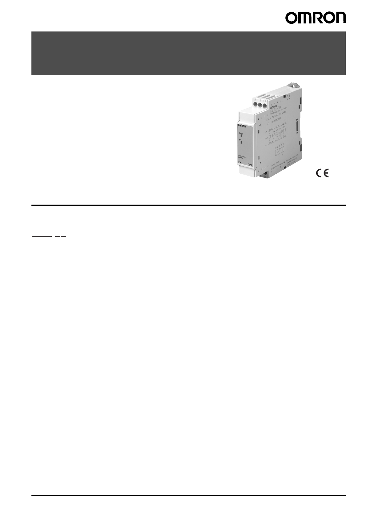
6Phase-sequence Phase-loss Relay K8AB-PH Cat. No. N145-E1-01
Safety Precautions
■Precautions for Safe Use
Make sure to follow the instructions below to ensure safety.
1. Do not use or keep this product in the following environments.
•Outdoors, or places subject to direct sunlight or wearing
weather.
•Places where dust, iron powder, or corrosive gases (in
particular, sulfuric or ammonia gas) exist.
•Places subject to static electricity or inductive noise.
•Places where water or oil come in contact with the product.
2. Make sure to install this product in the correct direction.
3. There is a remote risk of electric shock. Do not touch terminals
while electricity is being supplied.
4. Make sure to thoroughly understand all instructions in the
Instructions Manual before handling this product.
5. Make sure to confirm terminal makings and polarity for correct
wiring.
6. Tighten terminal screws firmly using the following torque.
Recommended torque: 0.54 N·m
7. Operating ambient temperature and humidity for this product
must be within the indicated rating when using this product.
8. There is a remote risk of explosion. Do not use this product where
flammable or explosive gas exists.
9. Make sure that no weight rests on the product after installation.
10.To enable an operator to turn off this product easily, install
switches or circuit breakers that conform to relevant requirements
of IEC60947-1 and IEC60947-3, and label them appropriately.
■Precautions for Correct Use
For Proper Use
1. Do not use the product in the following locations.
•Places subject to radiant heat from heat generating devices.
•Places subject to vibrations or physical shocks.
2. Make sure to use setting values appropriate for the controlled
object. Failure to do so can cause unintended operation, and may
result in accident or corruption of the product.
3. Do not use thinner or similar solvent for cleaning. Use commercial
alcohol.
4. When discarding, properly dispose of the product as industrial
waste.
5. Only use this product within a board whose structure allows no
possibility for fire to escape.
About Installation
1. When wiring, use only recommended crimp terminals.
2. Do not block areas around the product for proper dissipation of
heat. (If you do not secure space for heat dissipation, life cycle of
the product will be compromised.)
3. To avoid electrical shocks, make sure that power is not supplied to
the product while wiring.
4. To avoid electrical shocks, make sure that power is not supplied to
the product when performing DIP switch settings.
Noise Countermeasures
1. Do not install the product near devices generating strong high
frequency waves or surges.
2. When using a noise filter, check the voltage and current and
install it as close to the product as possible.
3. In order to prevent inductive noise, wire the lines connected to the
product separately from power lines carrying high voltages or
currents. Do not wire in parallel with or on the same cable as
power lines.
Other measures for reducing noise include running lines along
separate ducts and using shield lines.
To avoid faulty operations,
malfunctions, or failure, observe the
following operating instructions.
1. When turning on the power, make sure to realize rated voltage
within 1 second from the time of first supply of electricity.
2. Make sure to use power supply for operations, inputs, and
transformer with the appropriate capacity and rated burden.
3. Maintenance and handling of this product may only be performed
by qualified personnel.
4. Distortion ratio of input wave forms must be 30% or less. Use of
this product with circuits that have large distortion in wave forms
may result in unwanted operations.
5. Using this product for thyristor controls or inverters will result in
errors.
6. When setting the volume, adjust the control from the minimum
side to the maximum side.

In the interest of product improvement, specifications are subject to change without notice.
ALL DIMENSIONS SHOWN ARE IN MILLIMETERS.
To convert millimeters into inches, multiply by 0.03937. To convert grams into ounces, multiply by 0.03527.
Cat. No. N145-E1-01
OMRON Corporation
Industrial Automation Company
Industrial Devices and Components Division H.Q.
Industrial Control Components Department
Shiokoji Horikawa, Shimogyo-ku,
Kyoto, 600-8530 Japan
Tel: (81)75-344-7119/Fax: (81)75-344-7149
Warranty and Application Considerations
Read and Understand this Catalog
Please read and understand this catalog before purchasing the products. Please consult your OMRON representative if you have any
questions or comments.
Warranty and Limitations of Liability
WARRANTY
OMRON's exclusive warranty is that the products are free from defects in materials and workmanship for a period of one year (or other
period if specified) from date of sale by OMRON.
OMRON MAKES NO WARRANTY OR REPRESENTATION, EXPRESS OR IMPLIED, REGARDING NON-INFRINGEMENT,
MERCHANTABILITY, OR FITNESS FOR PARTICULAR PURPOSE OF THE PRODUCTS. ANY BUYER OR USER ACKNOWLEDGES
THAT THE BUYER OR USER ALONE HAS DETERMINED THAT THE PRODUCTS WILL SUITABLY MEET THE REQUIREMENTS
OF THEIR INTENDED USE. OMRON DISCLAIMS ALL OTHER WARRANTIES, EXPRESS OR IMPLIED.
LIMITATIONS OF LIABILITY
OMRON SHALL NOT BE RESPONSIBLE FOR SPECIAL, INDIRECT, OR CONSEQUENTIAL DAMAGES, LOSS OF PROFITS, OR
COMMERCIAL LOSS IN ANY WAY CONNECTED WITH THE PRODUCTS, WHETHER SUCH CLAIM IS BASED ON CONTRACT,
WARRANTY, NEGLIGENCE, OR STRICT LIABILITY.
In no event shall the responsibility of OMRON for any act exceed the individual price of the product on which liability is asserted.
IN NO EVENT SHALL OMRON BE RESPONSIBLE FOR WARRANTY, REPAIR, OR OTHER CLAIMS REGARDING THE PRODUCTS
UNLESS OMRON'S ANALYSIS CONFIRMS THAT THE PRODUCTS WERE PROPERLY HANDLED, STORED, INSTALLED, AND
MAINTAINED AND NOT SUBJECT TO CONTAMINATION, ABUSE, MISUSE, OR INAPPROPRIATE MODIFICATION OR REPAIR.
Application Considerations
SUITABILITY FOR USE
OMRON shall not be responsible for conformity with any standards, codes, or regulations that apply to the combination of products in
the customer's application or use of the products.
Take all necessary steps to determine the suitability of the product for the systems, machines, and equipment with which it will be used.
Know and observe all prohibitions of use applicable to this product.
NEVER USE THE PRODUCTS FOR AN APPLICATION INVOLVING SERIOUS RISK TO LIFE OR PROPERTY WITHOUT ENSURING
THAT THE SYSTEM AS A WHOLE HAS BEEN DESIGNED TO ADDRESS THE RISKS, AND THAT THE OMRON PRODUCTS ARE
PROPERLY RATED AND INSTALLED FOR THE INTENDED USE WITHIN THE OVERALL EQUIPMENT OR SYSTEM.
Disclaimers
PERFORMANCE DATA
Performance data given in this catalog is provided as a guide for the user in determining suitability and does not constitute a warranty.
It may represent the result of OMRON's test conditions, and the users must correlate it to actual application requirements. Actual
performance is subject to the OMRON Warranty and Limitations of Liability.
CHANGE IN SPECIFICATIONS
Product specifications and accessories may be changed at any time based on improvements and other reasons. Consult with your
OMRON representative at any time to confirm actual specifications of purchased product.
DIMENSIONS AND WEIGHTS
Dimensions and weights are nominal and are not to be used for manufacturing purposes, even when tolerances are shown.
This manual suits for next models
1
Table of contents
Other Omron Relay manuals

Omron
Omron G9SA - User manual

Omron
Omron G3PA-450B-VD-2 User manual

Omron
Omron K8AK-AS1 24VAC/DC User manual

Omron
Omron G3PA-260B-VD User manual

Omron
Omron K8AB-VW Series User manual

Omron
Omron K8AB-PA1 User manual

Omron
Omron ZEN User manual

Omron
Omron K8AK-VW2 24 VAC/DC User manual

Omron
Omron MY4H User manual

Omron
Omron K8AK-VS User manual

Omron
Omron K8DT-PZ Series User manual

Omron
Omron MYK User manual

Omron
Omron K8AB-TH User manual

Omron
Omron MK-I - User manual

Omron
Omron Sti SR101A Operation manual

Omron
Omron K8AK-PH1 200/500VAC User manual

Omron
Omron J7KNA-AR User manual

Omron
Omron SR107AD Operation manual

Omron
Omron K8AK-AS User manual

Omron
Omron F3SP-T01 User manual