One Lux OMNI-LED DST OL12/2/M3/DST User manual

Features
> Fully compliant DALI, self-contained emergency lighting device (type 1)
> Intelligent, automatic self-test scheduling for non-DALI applications
> Integralstatus/identicationsounderwithuser-override
> Input for optional low-voltageemergencytestinitiationswitch
> Bi-colourred/greenstatusindicatorLEDwith500mm
leads supplied as standard
> User-selectable 1 or 3 hour autonomy
> Emergencyoutputpower(Typical):1.5W(2-cell),3W(3-cell),
4W(55V4-cell),3.5W(90V4-cell)and3W(200V4-cell)
> 3-poleswitchingprovidesfullisolationoflampconnectionsandmains
driver’spowersupplyduringemergencyoperation(Compatiblewith
mostdrivertypesupto2.5A)
> Constant-currentchargerwithreverse polarity and short-
circuit protection
> Designed and manufactured in Great Britain
> Complieswith:EN60598-2-22,EN61347-1,EN61347-2-7,EN61347-2-
13,EN62034,EN62386,EN55015,EN61000-3-2,EN61547
www.one-lux.com 1
Common Technical Data
InputSupplyVoltage 230V+/-10%
Supply Frequency 50/60Hz
OutputVoltageoftheRange 3-200Vdc
MaximumTCPoint 70°C
AmbientTemperatureRange 0°C-50°C
BatteryChargeTime 24Hours
EarthLeakageCurrent <0.5mA
IPRating IP20
Weight 90g
Model Number LED Voltage
Range
Number of
Battery Cells
OL12/2/M3/DST 3-12V 2
OL55/3/M3/DST 9-55V 3
OL55/4/M3/DST 9-55V 4
OL90/4/M3/DST 55-90V 4
OL200/4/M3/DST 90-200V 4
OL12andOL55productsareSELVcompliant.
Allversionssuppliedinstandardpackquantitiesof50weighing5.0Kg
Accessories
Seepages5to7forourrangeofbatteriesandbatteryaccessories.
Productspecicationsmaybesubjecttochangewithoutpriornotice.
Issue_4Nov2016
Product description
Omni-LEDDSTTMisarangeofDALISelf-Testemergencylighting
conversionmoduleshousedinacompactlow-proleenclosure,
andsuitableforusewithmaintained,self-containedLEDluminaires.
Theirconstant-powerdrivertechnologyhasaSELVisolatedoutput
andavailableinarangefrom3Vto200VDC.Theywillrunalmost
anyLEDlamporarray(includingsomeGU10andLineartubes),
so making it easy to produce a self-testing and addressable,
emergencyversionofyourexistingLEDluminairewithouttheneed
for separate ‘emergency’ LEDs or connectors.
Theyareavailablein2,3and4cellversionsforusewithNiCdor
NiMHbatteries.
EMERGENCY | ONE-LEDTM
OMNI-LED DSTTM | LED DALI EMERGENCY CONVERSION MODULE WITH SELF-TEST

www.one-lux.com 2
Model Number
Input Characteristics - Charging Mode
Duration selection CircuitWatts* InputCurrent InrushCurrent PowerFactor
OL12/2/M3/DST
1Hour 2.8W 0.03A 5Apk 0.45
3Hour 3W 0.03A 5Apk 0.45
OL55/3/M3/DST
1Hour 2.8W 0.03A 5Apk 0.44
3Hour 4.2W 0.04A 5Apk 0.47
OL55/4/M3/DST,OL90/4/M3/DST,
OL200/4/M3/DST
1Hour 3.4W 0.04A 5Apk 0.45
3Hour 4.8W 0.05A 5Apk 0.45
TECHNICAL INFORMATION
*ThisguremaybeusedforLENI‘ParasiticPower’calculations.
Model Number
Battery & Emergency Output Characteristics
Duration selection Battery
Type
Numberof
BatteryCells
BatteryVolts
(Range) RatedCapacity DDPVoltage ChargeCurrent
(Constant)
DischargeCurrent
Nominal/Range
LEDVoltage
Range
TypicalOutput
Power**
Uout Max
(openCircuit)
OL12/2/M3/DST
1 hour
NiCd/
NiMH
22-2.8V 1.6Ah 1.8V(min) 75-95mA 1.05A/(0.8-1.2A) 3-12V 1.5W 12V
3 hours 22-2.8V 4Ah 1.8V(min) 140-260mA 1.05A/(0.8-1.2A) 3-12V 1.5W 12V
OL55/3/M3/DST
1 hour 3 3-4.2V 1.6Ah 2.5V(min) 75-95mA 1.05A/(0.8-1.2A) 9-55V 3W 60V
3 hours 33-4.2V 4Ah 2.5V(min) 140-260mA 1.05A/(0.8-1.2A) 9-55V 3W 60V
OL55/4/M3/DST
1 hour 44-5.6V 1.6Ah 3.5V(min) 75-95mA 1.05A/(0.8-1.2A) 9-55V 4W 60V
3 hours 4 4-5.6V 4Ah 3.5V(min) 140-260mA 1.05A/(0.8-1.2A) 9-55V 4W 60V
OL90/4/M3/DST
1 hour 4 4-5.6V 1.6Ah 3.5V(min) 75-95mA 1.05A/(0.8-1.2A) 55-90V 3.5W 100V
3 hours 44-5.6V 4Ah 3.5V(min) 140-260mA 1.05A/(0.8-1.2A) 55-90V 3.5W 100V
OL200/4/M3/DST
1 hour 44-5.6V 1.6Ah 3.5V(min) 75-95mA 1.05A/(0.8-1.2A) 90-200V 3W 205V
3 hours 4 4-5.6V 4Ah 3.5V(min) 140-260mA 1.05A/(0.8-1.2A) 90-200V 3W 205V
EMERGENCY | ONE-LEDTM
OMNI-LED DSTTM | LED DALI EMERGENCY CONVERSION MODULE WITH SELF-TEST
**Seegraphsonpages3and4foroutputcharacteristics.

www.one-lux.com 3
TECHNICAL INFORMATION
LED lamp output - Shaded area indicates typical forward voltage (Vf) vs forward current (If) expected throughout discharge duration.
4W - OL55/4/DST
0
100
200
300
400
500
600
3681114
LED current [mA]
LED voltage [V]
1.5W - OL12/2/DST 3W - OL55/3/DST
0
50
100
150
200
250
300
350
400
450
500
550
600
9 1114171922252730333538414346485154
LED current [mA]
LED voltage [V]
0
50
100
150
200
250
300
350
400
450
500
550
600
9 1114171922252730333538414346485154
LED current [mA]
LED voltage [V]
EMERGENCY | ONE-LEDTM
OMNI-LED DSTTM | LED DALI EMERGENCY CONVERSION MODULE WITH SELF-TEST

www.one-lux.com 4
TECHNICAL INFORMATION
EMERGENCY | ONE-LEDTM
OMNI-LED DSTTM | LED DALI EMERGENCY CONVERSION MODULE WITH SELF-TEST
LED lamp output - Shaded area indicates typical forward voltage (Vf) vs forward current (If) expected throughout discharge duration.
30
40
50
60
70
80
55 60 65 70 75 79.5 84.7 89.8
LED current [mA]
LED voltage [V]
3.5W - OL90/4/DST
0
10
20
30
40
50
60
70
80
90 101.3 109.2 117 124.8 132.6 140.4 148.1 155.9 163.7 171.4 179.1 186.8 200
LED current [mA]
LED voltage [V]
3.0W - OL200/4/DST

www.one-lux.com 5
Model Number
NiCd Batteries NiMH Batteries
Duration selection NCD24SS NCD24BS NCD34SS NCD34BS NCD44SS NCD44BS NCD216SS NCD316SS NCD416SS NMH24SS NMH34SS NMH44SS
ApplicableEndCaps
(2 required per battery) E-E-E-E/SubC E/SubC E/SubC E/18700 E/18700 E/18700
OL12/2/M3/DST
1Hour 4
3Hour 4 4 4
OL55/3/M3/DST
1Hour 4
3Hour 4 4 4
OL55/4/M3/DST,OL90/4/
M3/DST,OL200/4/M3/DST
1Hour 4
3Hour 4 4 4
BATTERY AND END CAP ACCESSORY ASSIGNMENT
Applicable Battery Packs and End Caps to OMNI-LEDTM models
EMERGENCY | ONE-LEDTM
OMNI-LED DSTTM | LED DALI EMERGENCY CONVERSION MODULE WITH SELF-TEST
Product description
> Endcapssuitableforusewith‘stick’Dsizebatteries
> Endcapsuitableforusewith‘stick’SubCbatteries
> Endcapsuitableforusewith‘stick’18700NickelMetalHydridebatteries
Properties
> Providesaconvenientandsecuremountingoptionforcylindricalbatteries
> MouldedinUL94-V0ratedplastic
> ‘E’versionoffersslidetogetherfeaturetoproducesecureside-bysideconguration
> Linkwiresavailableseparately
> Slotted for tag connection or outlet for pre-soldered connections
BATTERY END CAPS NiCd Batteries - Ordering Information
ProductCode E E/Slotted E/18700 E/SubC
FixingCenters
whentted
Battery
Length (L)
+20mm
Battery
Length (L)
+17mm
Battery
Length (L)
+16mm
Battery
Length (L)
+19mm
Maximum
Lengthwhen
tted
Battery
Length (L)
+37mm
Battery
Length (L)
+34mm
Battery
Length (L)
+23mm
Battery
Length (L)
+40mm

www.one-lux.com 6
ACCESSORIES | NICKEL CADMIUM (NiCd) BATTERIES
Product description
> HightemperatureNickelCadmiumbatteries
for Emergency Lighting use
> SuitableforusewithallOne-LUXproducts
> 1-yearwarranty
Properties
> Ratedforcontinuousoperationat55°Cand
meets the 4 year design life as per Annex A of
EN60598-2-22
> ComplieswithIEC61951-1
> Suppliedwithsuitableconnectors
> Availableincustomcongurations
> 4Ah‘D’sizecells
> Other capacities available
> Refertobatterydatasheetforfurther
information
Common Technical Data
AbsoluteMaximumTemperature 70˚C
MaximumContinuousTemperature 55˚C
MinimumAmbientTemperature 5˚C
ChargeRequirements C/20for24hoursConstantCurrent(CC)
Storage 0-25˚Cfor12months
Disposal at registered treatment facility only
Table of Dimensions
Dimensions NCD24SS NCD24BS NCD34SS NCD34BS NCD44SS NCD44BS NCD216SS NCD316SS NCD416SS
Length (L) 116mm 68mm 175mm 102mm 234mm 136mm 86mm 131mm 175mm
Width(W) 34mm 63mm 34mm 63mm 34mm 63mm 23mm 23mm 23mm
Height(H) 34mm 36mm 34mm 36mm 34mm 36mm 23mm 23mm 23mm
Fixing (l) n/a 32mm 64mm
Fixing(w) 40mm 40mm 40mm
IECCellSize ‘D’ ‘Sub-C’(SC/Cs)
NiCd Cable Assemblies Connector Type Wire Length Connector Dimensions
CAS031requiredwithpacks(BS)
(Sold separately)
MiniJSTplugto
Amp ‘mate-n-lok’ (male)
250mm N/A
N/A
CAS020requiredwithsticks(SS)
(Sold separately)
MiniJSTplugtoRed&Black
wireswithsockets
500mm 4.8mmx0.8mm
6.3mmx0.8mm
CAS012-linkwire
(Sold separately)
Whitewire
(female/female) 100mm 6.3mmx0.8mm(positive)
4.8mmx0.8mm(negative)
NiCd Batteries - Ordering Information
ProductCode NCD24SS NCD34SS NCD34BS NCD44SS NCD44BS NCD216SS NCD316SS NCD416SS
Box Quantity 40 30 30 20 22 140 60 60
Weight 11kg 12kg 13kg 10.8kg 12kg 14.5kg 10kg 12kg
PositiveNegative
Length (L)
Height(H)
Length (L)
Fixing (l)
Fixing(w)
Height(H)
Width(W)
EMERGENCY | ONE-LEDTM
OMNI-LED DSTTM | LED DALI EMERGENCY CONVERSION MODULE WITH SELF-TEST

www.one-lux.com 7
ACCESSORIES | NICKEL METAL HYDRIDE (NiMH) BATTERIES
Product description
> HightemperatureNickelMetalHydride
batteries for emergency lighting use
> SuitableforusewithallOne-LUXproducts
> 1-yearwarranty
Properties
> Ratedforcontinuousoperationat50°Cand
meets the 4 year design life as per Annex A of
EN60598-2-22
> ComplieswithIEC61951-2
> Suppliedwithsuitableconnectors
> Availableincustomcongurations
> 4Ah‘18700’sizecells
> Other capacities available
> Refertobatterydatasheetforfurther
information
Common Technical Data
AbsoluteMaximumTemperature 70˚C
MaximumContinuousTemperature 50˚C
MinimumAmbientTemperature 5˚C
ChargeRequirements C/20for24hoursConstantCurrent(CC)
Storage 0-25˚Cfor6months
Disposal at registered treatment facility only
Table of Dimensions
Dimensions NMH24SS NMH34SS NMH44SS
Length (L) 140.5mm 214.5mm 284mm
Diameter (D) 20mm 20mm 20mm
IECCellSize ‘18700’
NiMH Cable
Assemblies Connector Type Wire Length Connector Dimensions
CAS024/JST-wireset
(Sold separately)
MiniJSTplugtoRed&Black
wireswithspade&socket 700mm Red4mm(socket)
Black3.5mm(spade)
CAS070-linkwire
(Sold separately) Blackwire(male/female) 300mm 3.5mm&4mm(spade&
socket)
NiMH Batteries - Ordering Information
ProductCode NMH24SS NMH34SS NMH44SS
Box Quantity 50 45 54
Weight 7kg 11kg 14.5kg
Length (L)
Diameter (D)
NickelMetalHydride(Ni-MH)
EMERGENCY | ONE-LEDTM
OMNI-LED DSTTM | LED DALI EMERGENCY CONVERSION MODULE WITH SELF-TEST

www.one-lux.com 8
Disclaimers
Omni-LEDDSTTM module and its associated accessory products have been
manufacturedanddesignedtocomplywiththerequirementsofEN60598-2-22
in addition to the standards detailed on page 1 of this document. Operation
beyondtheparametersspeciedinthisdocumentandtheassociated
standards may result in reduced performance and ultimate premature failure,
withthewarrantymadevoid.Itistheluminairemanufacturer’sresponsibility
toensurecomplianceoftheluminairetorelevantStandards.Thespecier/
systemdesignershouldfollowtheluminairemanufacturer’sspecicationsand
beawareoftheenvironmenttowhichtheluminaireandthesecomponentsare
usedandensurecompatabilityofOne-LUXproductswithothercomponents
inthelighting/DALIsystem.Installationshouldbeinlinewiththefollowing
guides.PleasecontactourTechnicaldepartmentifyouareinanydoubt.
Precautions
Omni-LEDDSTTMmoduleshouldbeinstalledasperthefollowingguidelines,
electric shock or damage to the product may result if incorrectly installed.
Theluminaireshouldbeinstalledbyaqualiedandcompetentelectrician.
If the luminaire is to be mounted in an external location, consider the battery
astemperaturesbelow0°Cmaybefrequentincoldmonths.Inthiscase,
thedesignlifeof4yearswillbecompromisedandmorefrequentbattery
replacementsmaybeneeded.Likewise,iftheluminaireissituatedinahot
environmentwherethetemperatureismaintainedat25°Corabove,orsited
nexttolargepanesofglassinwhichcaseitmaybeexposedtothermal
magnication.
ItisrecommendedthatIP65luminairesareavoidedforuseininternal
applications as undue thermal stress may result.
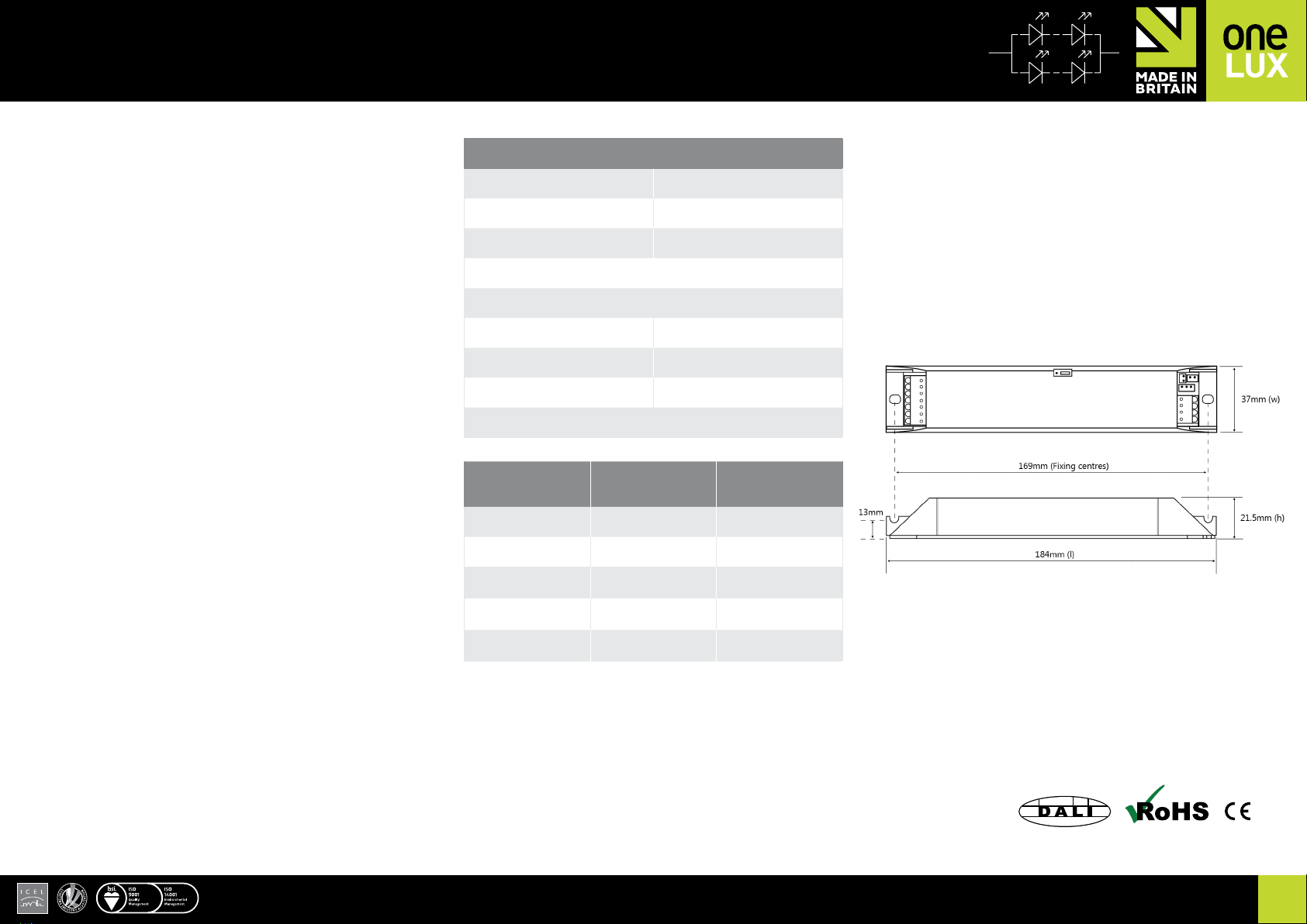
Installation notes
WirePreparation:maximumstriplength10mm(recommended6mm)
Min/maxConductorsizes:0.5-1.5mm2.
BesteffortshouldbemadetokeeptheOmni-LEDDSTTM module and battery
awayfromdirectsourcesofheat,i.e.mainsLEDdriversandLEDlamps.Avoid
obstructingairowaroundthesidesoftheOmni-LEDDSTTM module and other
electronicproducts.Allowaclearanceof10mmormorewhereverpossible.
LampConnectionsshouldbekeptasshortaspossibleandunderno
circumstances exceed 1m for self-contained luminaires.
TheOmni-LEDDSTTMmoduleshouldbesecuredusingbothxingpointsand
theuseofM4x6mmscrewsarerecommendedformostapplications.
Test Switch input (Optional accessory)
TheOmni-LEDDSTTM module offers the facility for the user to perform a
multiplefunctionswithaswitchconnectedtothe‘TESTSWITCH’input.
Anon-latchingpush-to-makeswitchshouldbeusedasshowninthewiring
diagramsonPage11.Seebelowfordetailsofuse.
EMCconsiderations:Mainsinputconnectionsshouldbeasfarfromthelamp
leadsaspossibleandnoideallylessthan10cm.Mainsinputwiresshouldbe
as short as possible and run direct from input terminations to the Omni-LED
DSTTM product; they should not run alongside the case.
OtherEMCtips:
> Keepthelampwiresraisedoffanyearthedmetalwork
> Twistmainsleadstogetherwhen‘looping’or‘throughwiring’
Theswitchedandun-switchedlivesmaybejoinedtogetherforcontinuous
operation(un-switched)applications.
TheOmni-LEDDSTTMmoduleprovidesSELVreinforcedinsulationbetween
the mains supply and battery charging circuit and employs self-resetting
INSTALLATION
EMERGENCY | ONE-LEDTM
OMNI-LED DSTTM | LED DALI EMERGENCY CONVERSION MODULE WITH SELF-TEST
protectionagainstshort-circuitofbatteryterminals.Normalchargingwill
resumeautomaticallyonceafaultisremoved.Themainssupplyshouldalways
bedisconnectedwhenservicingtheluminaire.
Ifotherdevicesareconnectedtotheun-switchedsupply,pleasebeawarethat
tomaintaincompliancewithEN60598-2-22thatineventofitsfailureitwillnot
affectotherdevicesonthesamecircuit.Inthiscasewerecommendtheuseof
separate fused terminal blocks to each device.
InternalfusesusedwithinOmni-LEDDSTTM module product are not user
serviceable.
CAUTION! Ensure the jumper setting located in the product lid is
congured correctly for the intended application and the associated
battery is of the correct capacity. See battery selection guide on page 5.
Autonomy Selection Information
Emergency Duration
Required Jumper Setting
3Hours(DefaultSetting)
1Hour
Test Switch Information
Function Test Switch Action
Disable Sounder Pressandholdforlongerthan5seconds
(Sounderbleepsonceforconrmation)
Enable Sounder Pressandholdforlongerthan5seconds
(Sounderbleepstwiceforconrmation)
StartaFunctionTest* Pressandrelease2timeswithin5seconds
Conrmphysicalselection Pressonceduringphysicalselectionmode
initiated by DALI system
StopIdentication Pressonceduringidenticationmode
to exit.

EMERGENCY | ONE-LEDTM
OMNI-LED DSTTM | LED DALI EMERGENCY CONVERSION MODULE WITH SELF-TEST
www.one-lux.com 9
INSTALLATION & OPERATION
Automatic Testing
Oncecommissioned,theOmni-LEDDSTTMmodulewillautomatically
determineifitisbeingusedinStandaloneSelf-Testmodeorconnectedtoa
DALInetwork.
IfStandaloneSelf-Testisdetected,itwillestablishrandomiseddelaytimes
toensurethenextscheduledtestsdonotcoincidewiththesametestof
adjacentluminaires.(Seetablebelowfordetailsof‘TestDelayTime’ranges).
Subsequentroutinetestingwillthentakeplaceaccordingtothe‘TestInterval’
timesdetailedinthetablebelow.
Whenascheduledtestisdue,theOmni-LEDDSTTMmodulewillcheckstatus
ofthe‘ControlSwitchLiveLin’totryanddetermineifthelampisalreadyin
useandavoiddisruptiontotheuserforupto36hourswhereverpossible.
IftheOmni-LEDDSTTMmoduledetectsitisinstalledonaDALInetwork,itwill
congureitselfaccordingtothedefaultDALIspecication. (Seetablebelow).
It is important to note that in DALI mode, randomisation will not be set
and it will await test delay times to be congured by the DALI master.
IntheeventoflossofcommunicationwiththeDALImaster,automatic
testingwillrevertbacktotheSelf-Test‘TestIntervals’,but‘TestDelayTimes’
willremainasconguredbytheDALImaster.
Automatic Testing Information
Test Type Mode Duration Test Delay time Test Interval / Occurrence Notes
CommissioningTest
Self-Test 1or3Hours* 24Hours Once* ThemodulewillcarryoutaDurationTest24hoursafterinitialpowerup.*Thistestcyclewillberepeatedifun-successfull
DALI 1or3Hours* 24Hours Once* ThemodulewillcarryoutaDurationTest24hoursafterinitialpowerup.*Thistestcyclewillberepeatedifun-successfull
FunctionTest
Self-Test 20Seconds 1-15Days Every28Days -
DALI 20Seconds 0 Every7Days Caution!FactorydefaultofzerotestdelaytimeissetforDALIMode
DurationTest
Self-Test 1or3Hours* 1-51Weeks Every51Weeks Themodulechecksifthelampisinusebeforeinitiatingatesttoavoiddisruption.Maximumtestdelayis36hours
DALI 1or3Hours* 0 Every52Weeks Caution!FactorydefaultofzerotestdelaytimeissetforDALIMode
Commissioning:
Oncetheluminairehasbeeninstalledandavailabilityoftheun-switched
supply is deemed stable, connect the battery, then apply mains power
to begin the commissioning process.Afterapplyingpower,theOmni-
LEDDSTTMindicatorLEDwillashredthengreenandthemodulewillcarry
outaninitial24hourchargeandathenafullDurationTest.Oncethis
commissioningtestiscomplete,afurther24hourswillbeneededtorecharge
the battery before normal use.
Thedurationofthetestwillbedeterminedbythecongurationlink,whichis
accessiblethroughtheenclosurelid.(Seepage8fordetails).
Caution should be taken to ensure the battery charge current
compatibility before adjusting conguration.
Ifitisanticipatedthattheun-switchedsupplymaybeinterrupted
beforenormaluse,weadvisethatthebatteryisleftdisconnectedand
commissioning is delayed until the supply is stable. If mains is not applied
afterconnectingthebattery,theunitwillcontinuetodrawaminimalamount
ofpowerfromthebatterywhilstinstandbymode.Continued use in this
state in excess of several months can cause permanent damage to some
batteries.
It may be necessary to repeat the initial charge/discharge process several
times to re-condition the battery and achieve full rated emergency duration.
Thiscanbeinitiatedbycyclingtheunswitchedmainssupplyoffand
on,oractivatingthetestswitchtwicewithin5seconds.Aftersuccessful
commissioning,thebatteryshouldbemarkedwiththedateofcommission.
AnOmni-LEDDSTTM module can be returned to standalone self test at any
timebydisconnectingitfromtheDALInetworkandforcingaFunctionTest
fromthetestswitchorbycyclingtheun-switchedmainssupply.(Seepage
10fordetails).
Tofullyresetalltesttimes,disconnectthemains,batterypowerand
DALIconnections.Oncepowerisrestored,thecommissioningcycleand
randomisationprocesswillbere-initiated.
ShortdischargeperiodseachmonthfortheFunctionTestwillnotadversely
affectOne-LUXbatteriesandshouldbeconsideredasamaintenance
exerciseforthebattery.Regularfulldischargecycleswillhoweveradversely
affect the design life of the battery, so excessive testing should be avoided
whereverpossible.
Afullsummaryofautomatictesttimingscanbeseeninthetablebelow.
ThestatusoftheOmni-LEDDSTTM module can be determined at any time
from the indicator LED. Details of the indicator LED status conditions and
optionaltestswitchfunctionalitycanbefoundonpage10.

INSTALLATION & OPERATION Continued
EMERGENCY | ONE-LEDTM
OMNI-LED DSTTM | LED DALI EMERGENCY CONVERSION MODULE WITH SELF-TEST
www.one-lux.com 10
Module Status Information
LED Colour LED Status On Time
(Seconds)
Off Time
(Seconds)
Sounder Purpose Action required
Green
VerySlowFlash 10 0.5 -Normalstatuswithfullychargedbattery(Commissionedunit) None-Instandbymodeandoperatingasnormal
SlowFlash 1.5 0.5 -First24hourchargeandDurationTest.(Non-Commissionedunit) None-Awaitcommissioningprocesstocomplete
Fast Flash 0.5 0.5 -FunctionTestorDurationTestinprogress.(Commissionedunit) None-Awaitcurrenttesttocomplete
Varied On Off On Off Purpose Action required
Green Long‘On’thenash 10 0.5 0.5 0.5 -Batterybeingcharged(Commissionedunit) None-Awaitbatterytocharge(Normally24Hours)
Red&Green(alternate) Fast Flash 0.5 0.5 0.5 0.5 -PhysicalselectenabledbyDALIsystemonly ConrmPhysicalselectwithoptionalTestSwitch
Module Status Information (Fault Conditions)
*A function test can also be initiated at anytime whilst mains power is present by cycling the un-switched mains supply or test switch off-on, 2 times within 5 seconds.
LED Colour LED Status On Time (Seconds) Off Time (Seconds) Sounder Cause Suggested action required
Red
SlowFlash 0.5 1.5 Yes 1)Possibleinitialcommissioning
durationtestfailed:
2)Possiblebatteryconnectionfault:
3)Possibleopencircuitorshort
circuitbattery:
4)Possiblebatterycapacityfault:
1)Ifitisanewinstallation,youcandetermineiftheOmni-LEDDSTTM passed the initial commissioning duration
testbycyclingthemainspoweroffthenon,whilstobservingtheindicatorLED.
a)IftheindicatorLEDashesredthengreenatpoweron,theOmni-LEDDSTTM module did not pass its
initialcommissioningdurationtestandwasawaitingfurtherinstruction.Cyclingthepowerasperabovehas
nowresettheprocessandanewtestwillbeattemptedin24hstime.(Aslongasthemainssupplyisnot
interrupted).Thisprocessmayneedtoberepeatedseveraltimestore-conditionnewbatteriestorestorefull
capacity, especially if they have been in storage for some time.
b)Ifaftercyclingthemainspoweroffthenon,theredindicatorremains,theunithaspasseditscommissioning
test,butmayhavefailedaroutinefunctionordurationtestbecauseofthecausesbelow.
2)Turnoffmainspower.Checkthebatteryconnectionsandrepair/replacefaultypartsifnecessary.Initiatea
function test to try and clear the fault indication. If the fault indication does not clear, proceed to step 3).
3)Turnoffmainspower.Disconnectthebatteryandmeasureifitsvoltageisbetween0.8-1.6VDCpercell.
Ifitsoutsidethisrange,thebatteryisfaultysoitshouldbereplaced.Onceanewoneisinstalled,turnonthe
mainspowertoinitiatethecommissioningprocess.Ifthevoltageiswithintherange,proceedtonextstep.
4)Totestthebatterycapacity,ensureithashad24hoursuninterruptedcharge,thenturnoffthemainspowerand
observeiftheratedemergencydurationisachieved.Ifitexceedstheratedduration,youcanreinstatepower
andinitiateafunctiontesttoclearthefaultindication.Iftherateddurationisnotachieved,anditwasa
commissionedbatterybefore,replacethebatteryandturnthemainspowerontoinitiateanew
commissioningtest.(Seepage9).
Fast Flash 0.5 0.5 Yes 1)Possiblelampfault:
2)Possibleinternalcircuitfault:
1)Disconnectthebatteryandturnoffmainspower.Checkthelampandwiringforfaultsordamage.Repair/
replaceasnecessary.Reconnectthebatteryandmainspower,theninitiateafunctiontesttoseeifthefaulthas
cleared. If the fault does not clear, proceed to step 2)
Caution, high voltages can be present at the lamp when the battery is connected even if the mains power
is turned off!!
2)Ifrepairing/replacingthelamporwiringdoesnotclearthefault,theremaybeaproblemwiththeOmni-LED
DSTTM. Turnoffmainspower,replacethemoduleandreinstatepowertocommissionthenewmodule.

www.one-lux.com 11
INSTALLATION
Wiring diagrams
EMERGENCY | ONE-LEDTM
OMNI-LED DSTTM | LED DALI EMERGENCY CONVERSION MODULE WITH SELF-TEST
This manual suits for next models
4
Table of contents
Popular Control Unit manuals by other brands

Instrutech
Instrutech CVM211 user manual

Keysight Technologies
Keysight Technologies 81490A user guide

EnOcean
EnOcean TCM 515 user manual

Sit
Sit 650 DELTA Use and Installation Instructions

Belimo
Belimo SHP Series Installation Recommendations

CIAT
CIAT XtraConnect 2 Installation, Operation, Commissioning, Maintenance