ONE OE-AC7000K-34 User guide

1
AC Charger
Installer Manual
OE-AC7000K-34 & OE-AC022K-34

2
Contents
1. Warning 3
2. Safety Precautions 4
3. Introduction
3.1 Product Technical Specication
3.2 Package Contents
3.3 Module Dierence
3.4 External Structure
5
6
7
8
8
4. Installation Instructions
4.1 Installation Preparation
4.2 Safety of Installation
4.3 Installation Process
9
9
10
10
5. Electrical Connection
5.1 Charger Appearance
5.2 Overview of Internal Structure
5.3 Wiring
13
13
14
15
6. Conguration
6.1 Power On
17
17
7. Hardware Setup 18
8. Charging Operation 21
9. Troubleshooting 22
10. Disposal 24
11. Warranty 24
12. Installation Details 29

3
WARNING
Do not try to open the charger. This EV
charger operates under high input and
output voltages, that are harmful to
human life.
Please strictly observe all warnings on
the device and user manual.
Unauthorized and non-professional
service personnel are forbidden to
remove the cover of this device.
Thank you for choosing One Electrical. We oer a wide range of
market leading electric vehicle charging products. To nd out
more, visit our website: www.oneelectrical.com

4
2. Safety Precautions
Before installing or operating the EV charger, please read the
user manual carefully to understand the correct practice of use.
Keep the user manual for future review.
1) Keep the charger away from explosive or ammable materials,
chemicals, vapors and other hazard objects.
2) Keep the charger socket clean and dry. If it gets dirty, please
wipe it with clean dry cloth. Do not clean when charger is in use.
3) Touching the socket core is strictly forbidden when power on.
4) Check the device defects, cracks, abrasions, and bare leakage.
If any of these conditions occur, do not use charger and contact
a professional.
5) Do not attempt to dissemble, repair, or ret the charger. Please
contact the relevant professional if necessary. Improper opera-
tion will result in device damage, electric leakage, etc.
6) In case any abnormal condition happens, please cut o all
input and output power supplies immediately.
7) Please protect charger from water and extreme weather
conditions, including rain and lightning.
8) Keep children away from the charger.
9) During charging, do not drive the electric vehicle. Charger
may only be used when the vehicle is stationary. Hybrid vehicles,
must only be charged when the engine is switched o.

5
3. Introduction
The OE-AC7000-34/AC7000-BE-34 is a single-phase AC
charger used for electric vehicle charging, with a protection
grade of IP65.
Designed according to Electric Vehicle Charging System Stand-
ard EN 61851-1: 2011 and EN 61851-22: 2002, the charger is
compliant with the relevant industrial
standards and safe for usage.
The charger is operated by scanning the RFID card which starts
or stops the charging session. The LED indicator on the front
panel helps you to understand what state the charger is in by
indicating dierent colours.
Compatible with all types of cables, the socket locks the charging
cable into the charger to ensure safe charging. It is water and
rust proof, making it suitable for outdoor operation and
maintenance.
The charger is provided with a wall-mounted bracket, and an
optional oor-stand accessory is available at an additional cost.
With internet connection through 4G/WIFI/Ethernet, users are
able to monitor and manage the charger operation from the PC
backend or mobile app.
6
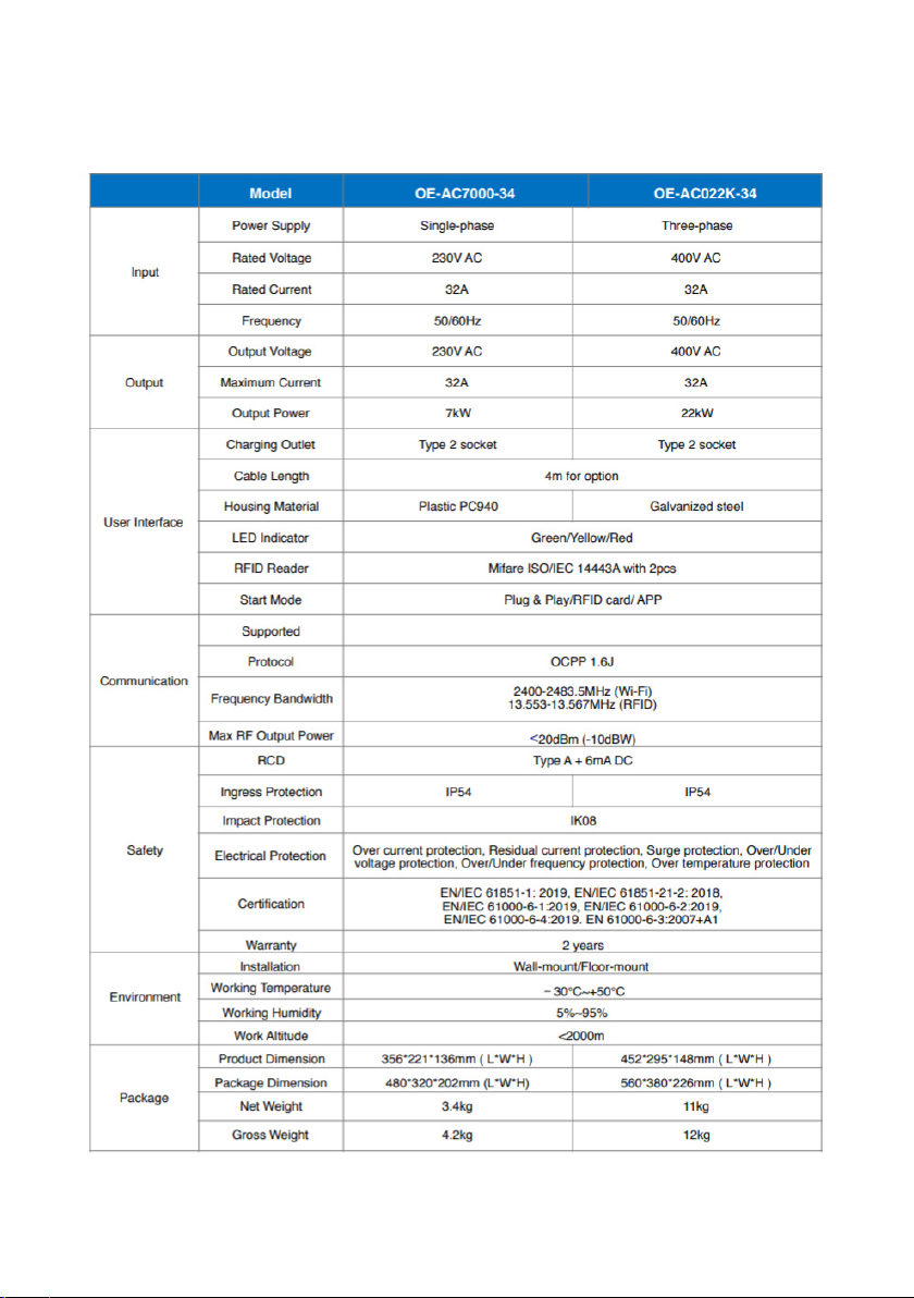
3.1 Product Technical Specication
Wi-Fi / SIMWi-Fi / SIM

7
3.2 Package Contents
Your package should contain the following items:
Please ensure you have all items and complete a visual
inspection. If there is any damage or missing items, please notify
the seller immediately.
8
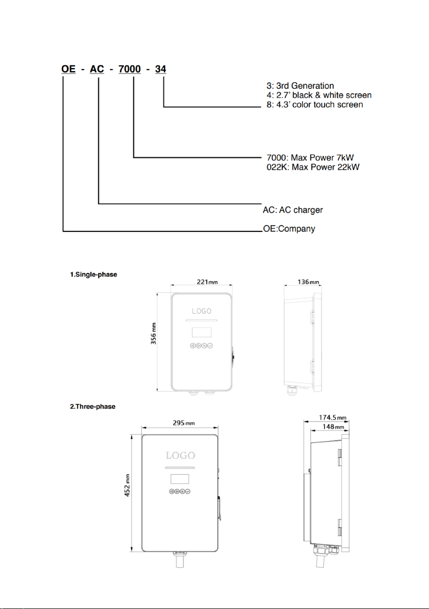
3.3 Module Dierence
3.4 External Structure

9
4. Installation Instructions
4.1 Installation Preparation
Tools Required
Cables & Materials

10
4.2 Safety of Installation
Installation Notice
Electrical devices should only be installed, operated, and
maintained by a qualied professional. The manufacturer does
not assume responsibility for any consequences arising out of
the use of this device. A qualied person is one who has certied
skills and knowledge related to the construction, installation and
operation of this type of electrical device and who has received
safety training to recognize and avoid the hazards involved.
All applicable local, regional, and national regulations must be
applied when installing, repairing and maintaining this device.
Installation Inspection
Ensure the charger’s location allows good operational access for
normal use and repair & maintenance.
Check that the AC input components within the premise’s pow-
er supply are correctly tted with the required protection items
prior to installation of the charger.
4.3 Installation Process
Wall-mount Installation: single-phase
1. Based on the prole of the attached installation board, drill 3 x
Φ 6*35 mm holes on the wall, and insert the expansion pipe.
2. Lock the 2 x M4*32mm self-tapping screws into the expansion
pipe, leaving a 5mm space, between the screw head to the wall.
3. Open the upper cover of charger, hang it on the 2x M4*32 mm
screws, lock it into the bottom M4*32 mm self-tapping screw
and then cover the sealing cap.
This manual suits for next models
1
Table of contents
Other ONE Batteries Charger manuals


