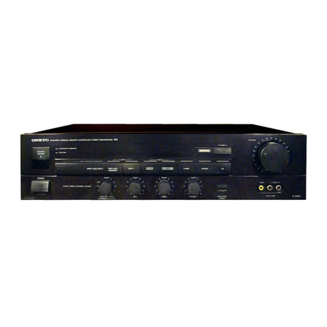
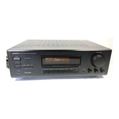
Onkyo R-100 User manual

Artistry
in
Sound
ONKYO.
R-1
00
FM/AM
Tuner
Amplifier
UKW/MW-Receiver
Ampli-Tuner
FM/AM
Sintonizador
de
FM/AM-Amplificador
FM/AM
Tuner/Versterker
Férstarkare
med
Inbyggd
FM/AM-Radiodel
Amplificatore
Sintonizzatore
FM/AM
Instruction
Manual
.............::000+
3
Bedienungsanleitung...........+
15
Manuel
d’instructions
.............
27
Manual
de
instrucciones
........
40
Gebruiksaanwijzing...........00
52
BrukSanviSning
........cssssseeeeeee
65
Istruzioni
per
|’USO
.........:.2:ee00
78

e
Congratulations
on
your
purchase
of
the
ONKYO
R-100
Tuner-Amoplifier.
@
Please
read
this
manual
thoroughly
before
making
connections
and
turning
power
on.
@
Following
the
instructions
in
this
manual
will
enable
you
to
obtain
optimum
performance
and
listening
enjoyment
from
your
new
R-100.
®
Please
retain
this
manual
for
future
reference.
Features
oe
(AAPA
®
Elegant
New
Design
Features
Sleek,
Unadorned
Styling
and
Titanium
Steel.Colored
Finish
@
Plenty
of
Clean
Power
:
35
watts
of
rated
power
per
channel
into
8
ohms
with
no
more
than
0.025%
total
harmonic
distortion.
45
watts
per
channel
into
8
ohms
(DIN).
(2
x
105
watts
dynamic
power
at
2
ohms.)
®
Discrete
Output
Stage
Instead
of
|C
power
amp
circuitry,
the
R-100
employs
a
discrete
output
stage
for
effortless
drive
of
low
impedance
loads.
Low
distortion
Linear
Switching
and
the
high
quality
parts
used
throughout
reflect
Onkyo’s
dedication
to
audio
excellence
not
merely
in
its
high
end
amplifiers
but
across
the
board.
Direct
Input
Function
for
All
Sources
Automatic
Tuning
Processor
Input
and
Output
Jacks
30-Station
FM/AM.
Random
Preset
Tuning
with
“Jump”
Function
to
Skip
Over
Non-Preset
Stations
Attractive
Liquid
Crystal
Display
Allows
Instant
Confirmation
of
Essential
Information
Included
45-Key
System
Remote
Control
Unit
Even
Covers
Tone
Controls
@
Heavy
Duty
Speaker
Terminals
Accommodate
Banana
Plugs
Important
safeguards
“WARNING”
“TO
REDUCE
THE
RISK
OF
FIRE
OR
ELECTRIC
SHOCK,
DO
NOT
EXPOSE
THIS
APPLIANCE
TO
RAIN
OR
MOISTURE.”
CAUTION
“TO
REDUCE
THE
RISK
OF
ELECTRIC
SHOCK,
DO
NOT
REMOVE
COVER
(OR
BACK).
NO
USER-SERVICEABLE
PARTS
INSIDE.
REFER
SERVICING
TO
QUALIFIED
SERVICE
PERSONNEL.”
ATTENTION
FOR
BRITISH
MODEL:
@
Replacement
and
mounting
of
an
AC
plug
on
the
power
supply
cord
of
this
unit
should
be
performed
only
by
qualified
service
personnel.
@
IMPORTANT:
The
wires
in
the
mains
lead
are
coloured
in
ac-
cordance
with
the
following
code:
Blue:
Neutral
Brown:
Live
As
the
colours
of
the
wires
in
the
mains
lead
of
this
apparatus
may
not
correspond
with
the
coloured
markings
identifying
the
terminals
in
your
plug,
proceed
as
follows:
The
wire
which
is
coloured
blue
must
be
connected
to
the
terminal
which
is
marked
with
the
letter
N
or
coloured
black.
The
wire
which
is
coloured
brown
must
be
connected
to
the
terminal
which
is
marked
with
the
letter
L
or
coloured
red.
Observe
the
following
precautions
to
obtain
troublefree
perform-
ance
for
many
years.
1.
Avoid
places
subject
to
direct
sunlight
or
extremely
high
or
low
temperatures.
2.
Avoid
damp
or
dusty
places
and
places
directly
affected
by
vibrations
from
the
speakers.
In
particular,
avoid
placing
the
unit
on
or
above
one
of
the
speakers.
3.
Avoid
unstable
locations
and
high
places
from
which
the
unit
could
fail.
4.
Ventilation
—
The
unit
should
be
situated
so
that
its
location
or
position
does
not
interfere
with
proper
ventilation.
For
ex-
ample,
the
unit
should
not
be
placed
on
a
bed,
sofa,
rug
of
similar
surface
that
could
block
the
ventilation
openings
or
placed
in
a
built-in
installation,
such
as
a
bookcase
or
cabinet,
that
could
impede
the
flow
of
air
through
the
ventilation
openings.
5.
Heat
—
The
unit
should
be
situated
away
from
heat
sources
such
as
radiators,
heat
registers,
or
other
appliances
(including
amplifiers)
that
produce
heat.
6.
Cleaning
of
the
internal
parts
should
be
performed
only
by
qualified
service
personnel.
7.
Spillage
—
Care
should
be
taken
so
that
objects
do
not
fall
and
liquids
are
not
spilled
into
the
enclosure
through
the
openings.
8.
Damage
Requiring
Service
-
The
unit
should
be
serviced
by
~
qualified
service
personnel
when:
A.
The
power
supply
cord
or
the
plug
has
been
damaged;
or
B.
Objects
have
fallen
or
liquid
has
been
spilled
into
the
unit;
|
or
C.
The
unit
has
been
exposed
to
rain;
or
D.
The
unit
does
not
appear
to
operate
normally
or
exhibits
a
marked
change
in
performance;
or
E.
The
unit
has
been
dropped
or
the
enclosure
damaged.
9.
Servicing
—
The
user
should
not
attempt
to
service
the
unit
beyond
that
described
in
the
operating
instructions.
All
other
servicing
should
be
referred
to
qualfied
service
personnel.
@
This
apparatus
complies
with
requirements
of
EC
directive
87/308/EEC.

®@
Control
positions
and
functions
(See
page
7,
8)
©
Bedienungselemente
und
Funktionen
(Siehe
Seite
18,
19,
20)
®
Position.et
fonction.
des
commandes
(Voir
en
page
31,
32)
@
Ubicacién
y
funciones
de
los
controles
(Consulte
la
pagina
43,
44,
45)
®
Plaats
en
funktie
van
de
bedieningsorganen
(Zie
biz
56,
57)
@
Reglage,
deras
placering
och
funktioner
..
(Se
sidan
68,
69,
70)
oe
®
Posizione
e
funzione
dei
comandi
(Vedere
pagina
81,
82,
83)
Artistry
in
Sound
TIMER
STAND-BY
SLEEP
STEREO
AUTO
MONO
SOURCE
DIRECT
MUTING
MEMORY
ONKYO
Ac174s
Remote
CONTROL
THANSMiTreR
FRI
POWER
INPUT
SELECTOR
TAPE
Tur
Loading
the
batteries
(See
page
13)
Einlegen
der
Batterien
(Siehe
Seite
25)
Mise
en
place
des
piles
(Voir
en
page
38)
Insercién
de
las
pilas
(Consulte
la
papina
50)
Plaatsen
van
de
batterijen
(Zie
biz.
63)
Batteriernas
isdttning
(Se
sidan
76)
inserimento
delle
batterie
(Vedere
pagina
88)
O

CONTENTS
CRATES
ciso2k
cele
sects
c
be
eels
Wa
ened
ee
eh
Operations
................:ccccscsecedseseieecresedscneeeterts
Important
safequards
...........ccceeteee
ences
eeeeene
Using
the
remote
control
transmitter..........
Precautions......sccccceeeen
Seber
evcteeeevaceduasyoss
feces
Troubleshooting
Quide
..........c.cccccsececeereeenenes
SySteEM
CONNECTIONES.........ceeceecsseeeeeeeeeeeens
eae
Specifications............cceeees
fire
eeie
vas
gdbuanaakactses
Control
positions
and
functions..................
INHALT
Eigenschatten
........::cseseeeeeeeeeeesenneseeeeseueeeeenas
15
Bedienung.
.......ccccceccseesssecsecccnececeeeeeeersaeereurers
Aufstellung
und
Wartungen
.......-..e
eee
Verwendung
des
Fernbedienungsteils
.........
VorsichtsmaBnahmen
..........ccceeeceeereeeeeenenees
Betriebsprobleme
und
deren
Behebung
AnschluBdiagra
mmm
........cccciccccceeeeeeeneeereeeeenes
Technische
Daten
Bedienungselermmente
und
Funktionen
..........
TABLE
DES
MATIERES
CaractGristiques
........ccccccsceesecnseeeeeeseeeeeeeearees
27
FONCTIONNEMENT
.........cceseecseceeeeeceeeneneseasenenoes
32
Mises
en
garde
importantes..............ccecceee
27
Utilisation
de
la
télécommande.........c.ccceeeee
38
Pr&CAUTIONS.
00.0
cecsccccecscencsccsnecenesrenrecesecsnenenses
27.
Tableau
de
d6pannage.
.......ccccccseeseecenveeneeneres
38
Connexions
Gu
SYSTEM...
eee
cere
eeeeeenes
238
SPECIFICATIONS
........
cece
eee
e
cece
eenteenteeneeuanes
39
Position
et
fonction
des
commandes...........
INDICE
CAracteriStiCAS
......cccccsesecesecsceseeeeeeenereseeseseaee
40
Operacione.
.........cseceeseccneeeeceeeeeeweneeeeaeesaneees
Normas
de
seguridad
importantes.
...............
Empleo
del
transmisor
de
contro!
remoto...
PreCAUGIONES
..-...ccccescccsessereceneeeeeeneeaneneeeeneees
Guia
para
la
solucién
de
los
problemas
.......
Conexiones
con
el
Sistema
...........cccceeeseeenees
Especificaciones
Ubicacién
y
funciones
de
los
controles.......
OPPO
Pee
errr
rer eer
re
rrr
reer
ere
rerre
riers
INHOUDSOPGAVE
KeNMErKen......ccceceeccerceesteceeeeencnseseeaeeeeeseeceneee
52
Bediening..........cccsccsessesneneesaneeunesereseesenenegscees
57
Belangrijke
voorzorgsmaatregelen
...............
52
Gebruik
van
de
afstandsbediening
...............
63
Wetenswaardig
heden
...........:ccccseeeerteneneeeenees
52
Verhelpen
van
Storingen
.......cccccccccseceseenesenes
63
AansluitinGeNn.........cccccccnecreseereeeeneeneneeeeeeenten
ee
53
Technische
Gegevens..........cccccccssecsseesseecereeres
64
Plaats
en
funktie
van
de
bedieningSOrgane
...........c::scceseceneeeeeeeeseees
INNEHALL
Egenskaper
.....-::.sceeeeeteeeneercsssneereresenseneerenenens
ANVANANING........-ececeeecee
ence
eeeneeeneneeneeesaaensaaans
Viktiga
sakerhetsatgarder
...........:scseseeeeees
Fjarrstyrning
med
fjarrkontrollen
............068
FérsiktighetSatgarder
............csccccsseseecseneneeeee
FOISGKIING
00305
.0ci
cisnedirsicdsdesciceasestadndsedccisdetvare
Systemanslutningar
..........cccecccerereeeeeseeeees
Tekniska
data
Reglage,
deras
placering
och
funktioner
.....
Caratteristiche
Funzionamento
importante
Uso
del
telecomando
Precauzioni
Guida
alla
soluzione
di
problemi
Collegamenti
di
sistema
Caratteristiche
tecniche
Posizione
e
funzione
dei
comandi

Precautions
1.
Warranty
Card
The
serial
number
is
written
on
the
rear
panel
of
this
unit.
Copy
the
serial
number
and
model
number
onto
your
warranty
card
and
keep
it
in
a
safe
piace.
2.
Recording
Copyright
Recording
of
copyrighted
material
for
other
than
personal
use
is
illegal
without
permission
of
the
copyright
holder.
3.
AC
Fuse
The
fuse
is
located
inside
the
chassis
and
is
not
user
serviceable.
if
power
does
not
come
on,
contact
your
Onkyo
service
center.
4.
Care
From
time
to
time.
you
should
wipe
off
the
front
and
rear
panels
and
the
cabinet
with
a
soft
cloth.
For
heavier
dirt,
dampen
a
soft
cloth
in
a
weak
solution
of
mild
detergent
and
water,
wring
it
out
dry,
and
wipe
off
the
dirt.
Following
this,
dry
immediately
with
a
clean
cloth.
Do
not
use
rough
material,
thinners,
alcohol
or
other
chemical
solvents
or
cloths
since
these
could
damage
the
finish
or
remove
the
panel
lettering.
5.
Power
WARNING
BEFORE
TURNING
ON
POWER
FOR
THE
FIRST
TIME,
READ
THE
FOLLOWING
SECTION
CAREFULLY.
@
Some
models
are
designed
for
use
only
with
the
power
supply
voltage
of
the
region
where
they
are
sold.
European
models,
(except
U.K.):
.
AC220V,
50Hz
U.K.
&
Australian
models:
AC
240V,
50Hz
Worldwide
models:
120
and
220V
switchable,
50/60Hz
®@
Voltage
Selector
(Rear
Panel)
Worldwide
models
are
equipped
with
a
voltage
selector
to
conform
with
local
power
supplies.
Be
sure
to
set
this
switch
to
match
the
voltage
of
the
power
supply
in
your
area
before
turning
the
power
switch
on.
Voltage
is
changed
by
sliding
the
groove
in
the
switch
with
a
screwdriver
to
the
right
or
left.
Contirm
that
the
switch
has
been
moved
all
the
way
to
the
right
or
left
before
turning
the
power
switch
on.
Models
without
a
voltage
selector
can
only
be
used
in
areas
where
the
power
supply
is
the
same
as
that
of
the
unit.
220V
120V
™
220V™,
120V
TU
at
AC120V
at
AC220V
@
Tuning
Step
Frequency
Switch
(Rear
Panel)
Worldwide
models
are
equipped
with
a
switch
that
controls
the
AM
(9kHz/10kHz)
and
FM
(50kHz/200kHz)
band
tuning
steps.
Be
sure
to
set
this
switch
to
match
the
tuning
step
frequency
in
your
area.
U.S.A.
and
Canada
10kHz/200kHz
Other
area
9kHz/50kHz
System
connections
General
Switch
the
power
button
off
before
performing
connections.
Also
be
sure
to
perform
left
and
right
channel
connections
properly.
AC
Outlets
@
SWITCHED:
These
outlets
are
switched
on
and
off
by
the
power
button
on
the
front
panel
and
remote
control
transmitter.
The
capacity
is
100
watts.
FM
Antenna
Connections
Use
the
T-shaped
antenna
if
you
live
in
an
area
where
signal
strength
of
FM
broadcasts
is
high.
Connect
the
antenna
to
the
FM.75
ohms
terminals
and
place
the
antenna
on
a
wall
or
other
surface
in
the
position
in
which
reception
is
best.
If
signal
strength
is
low
in
your
area,
use
a
multi-element
FM
outdoor
antenna.
Consult
your
Onkyo
authorized
service
center
about
the
right
type
of
antenna
for
your
area.
:
NOTES:
4.
Do
not
connect
both
the
indoor
T-shaped
antenna
and
an
outdoor
FM
antenna.
If
you
decide
to
install
an
outdoor
antenna,
be
sure
to
disconnect
the
indoor
T-shaped
antenna.
2.
Do
not
use
the
same
antenna
for
both
FM
and
TV
reception
since
the
FM
and
TV
signals
can
interfere
with
each
other.
\f
you
must
use
a
common
FM/TV
antenna,
use
a
directional
linkage
type
splitter.
Directional
linkage
type
splitter
To
receiver
To
TV
(or
VCR)
AM
Antenna
Connections
An
AM
loop
antenna
is
included
in
the
installation
instructions
bag.
Take
out
the
connection
line
and
connect
it
to
the
AM
antenna
terminals.
This
loop
antenna
can
be
placed
on
top
of
any
stable
surface
or
attached
to
a
wall.
Try
several
positions
to
determine
which
gives
the
best
reception.
Be
sure
the
antenna
is
not
near
a
speaker,
power
cord,
television
set,
VCR
or
motorized
appliances.
When
using
an
external
AM
antenna,
do
not
remove
the
loop
an-
tenna:
connect
both
antennas
to
the
AM
antenna
terminals.
AM
loop
antenna
assembly
Connect
to
the
AM
antenna
terminals.
Remove
the
vinyl
tie
and
take
out
the
connection
.
Bend
in
the
reverse
line.
direction.
a.
With
the
antenna
on
top
of
any
stable
surface
b.
With
the
antenna
attached
to
a
wall
Installation
hole
Mount
on
a
wall,
etc.
NOTE:
AM
reception
is
easily
affected
by
television
sets
and
VCRs.
Therefore,
AM
reception
may
be
poor
if
this
unit
is
placed
too
close
to
a
TV
or
a
VCR.

Do
not
connect
both
indoor
and
outdoor
FM
antennas.
!f:you
decide
to
install
an
outdoor
antenna,
be
sure
to
disconnect
the
indoor
feeder
antenna.
Outdoor
Indoor
T-shaped
AM
toop
FM
antenna
antenna
antenna
G-
ir
Q7IDGSI-2eveee
--©
ANTENNA
f
ogg
|
eT
PHONO
—
Cp
eM
752
Ground
connection
is
not
necessary
for
turntable
without
ground
lead.
TURNTABLE
COMPACT
DISC
PLAYER
(C-100)
FRI
remote
control
cable
TAPE
DECK
(K-100)
VIDEO
2
®
©
©)
56
"a
\
FREQ
STEP
A
MONITORS
OTHER
Usa
¥
OOOO
OOeD:
OOOOHDD:O@S-
Srape
Outdoor
AM
antenna
dP
SPEAKER
8mm
a
remove
insulation
GOS
MONITOR
TV
unscrew
'
1
1
t
iTuning
Step
Frequency
iSwitch
Worldwide
model
joni
PPEAKERS
&
©):
Fade
!
pROCESSOR
i
REMOTE
:
!
CONTROL
CAUTION:
SPEAKER
IMPEDANCE
4
OHMS
MIN
‘SPEAKER
Please
remove
the
jumper
plug
~~
~~.
|
when
a
graphic
equalizer
or
audio
1
processor
is
connected.
Refer
to
1|
page
12
for
more
details.
1
a
a
es
(RE
remote
contro}
cable
VIDEO
DISK
PLAYER
=o
twist
copper
strands
ae
here
ro)
AC
OUTLET
)
50
Cd
&
ne
*
Please
connect
the
K-100
or
C-100
AC
power
cord.
Voltage
Selector
Worldwide
model
only
4
/
VOLTAGE
SELECTOR
by
{
}
\
!
\
lig
row,
7
qe

Speaker.
Connections
(SPEAKERS)
1.
Connect
the
speakers
to
speaker
terminals.
2.
When
connecting
speakers,
proper
polarity
is
important.
Always
connect
the
(+)
terminal
(red)
on
this
equipment
to
the
(+)
terminal
on
the
speaker
and
the
(—)
terminal
(black)
on
this
equipment
to
the
(—)
terminal
on
the
speaker.
3.
The
load
impedance
of
each
speaker
system
connected
to
this
unit
must
be
at
least
4
ohms.
4.
When
using
only
one
speaker
or
when
you
wish
to
listen
to
monaural,
the
single
speaker
should
never
be
connected
in
parallel
to
both
the
right
and
left
channel
terminals
at
once.
Aliso,
do
not
connect
two
speakers
to
the
same
terminal.
Attach
speaker
cables
to
the
rear
panel
speaker
terminals
with
care,
being
sure
that
connections
are
made
firmly
and
that
there
is
no
possibility
of
a
short
circuit
occurring.
Connecting
Speaker
Cables
4.
Remove
about
8
mm
of
insulation
from
the
end
of
the
speaker
cable.
2.
Twist
the
exposed
copper
strands
together
tightly.
3..
Unscrew
the
speaker
terminal
part
way
by
turning
it
counter-
clockwise.
4.
Insert
the
exposed
copper
portion
of
the
cable
all
the
way
into
the
opening
in
the
speaker
terminal.
Insert
the
copper
strands
in
the
same
direction
as
that
in
which
the
screw
is
turned.
If
they
are
inserted
in
the
reverse
direction,
they
will
come
out
when
the
screw
is
tightened.
5.
Tighten
the
terminal
screw
by
turning
it
clockwise.
6.
Check
to
make
sure
that
none
of
the
uninsulated
copper
portion
of
the
cable
is
exposed.
CAUTION:
When
using
banana
plugs,
make
sure
the
speaker
terminal
screws
are
screwed
in
firmly
before
inserting
banana
plugs.
Connections
for
Remote
Control
(REMOTE
CONTROL)
A
cassette
tape
deck
and
compact
disc
player
that
have
the
Onkyo
fRI
mark
can
be
operated,
using
the
accessory
remote
control
:
Remote
Interactive)
transmitter.
(
FRI
R-100
COMPACT
DISC
eee
PLAYER
C-100
|
°°
CASSETTE
TAPE
fA
REMOTE
DECK
K-100
CONTROL
©
FRI
remote
control
cable
An
RI
remote
control
cable
equipped
with
a
0.136”
(3.5mm)
diameter
miniature
two-conductor
phone
plug
is
attached
to
compact
disc
player
C-100
and
cassette
tape
deck
K-100,
with
the
FAY
mark.
To
use
an
Onkyo
compact
disc
player
and
cassette
tape
deck
with
the
FI
mark,
insert
the
accessory
remote
control
cable
plug
into
the
REMOTE
CONTROL
jacks.
As
far
as
connecting
sequence
is
concerned,
it
doesn’t
matter
whether
the
cable
is
connected
from
the
R-100
to
the
cassette
tape
deck
or
to
the
compact
disc
player.
The
remote
control
transmitter
is
operated
by
facing
it
towards
the
remote
control
sensor
of
the
R-100.
Remote
control
operation
is
not
possible
when
only
the
remote
Gontrol
cable
is
connected.
Remote
control
cable
and
connecting
|
cable
must
be
connected.
Turntable
Connections
(PHONO)
Connect
the
output
leads
of
the
turntable
to
the
PHONO
jacks.
Be
sure
to
connect
the
ground
(earth)
lead
wire
from
the
turntable
to
the
ground
terminal
(GND):
“Lack
of
proper
ground
connection
will
cause
hum.
Turntables
not
provided
with
GND
wires
do.
not
need
to
be
connected.
1.
Place
the
turntable
on
a
firm
shelf
or
deck
free
from
vibrations
(especially
those
generated
by
the
speaker
system).
If
the
turntable
is
permitted
to
pick
up
such
unwanted
vibrations,
not
only
will
the
performance
of
the
unit
drop,
but-distortion
in
the
bass
frequencies
and
howling
in
the
speakers
may
also.
occur.
Check
the
turntable
instruction
manual
for
any
other
precautions.
The
loud
noises
that
occur
when
connecting
and
disconnecting
the
turntable
leads,
replacing
the
cartridge
or
lowering
the
tonearm
could
damage
the
speakers.
Always
turn
the
power
switch
off
before
making
connections.
wn
Compact
Disc
Player
(CD)
Connect
the
output
leads
of
the
CD
player
to
the
CD
jacks.
An
Onkyo
CD
player
with
remote
control
that
has
the
1
mark
can
be
operated
by
the
R-100.
(Please
refer
to
“Connections
for
Remote
Contro!”.)
For
more
details,
refer
to
your
CD
player
instruction
manual.
Tape
Deck
Connections
(TAPE)
Connect
the
tape
deck
output
leads
to
the
PLAY
jacks
and
the
tape
deck
input
leads
to
the
REC
jacks
of
this
unit.
For
more
details,
refer
to
your
tape
deck
instruction
manual.
Video
Disc
Player
(or
Video
Cassette
Player)
Connections
(VDP)
Use
the
VDP
jacks.
Connect
the
VIDEO
output
of
the
video
disc
player
to
the
R-100
VDP
“VIDEO”
jack
and
the
AUDIO
output
to
the
VDP
“AUDIO”
jacks.
The
VDP
jacks
are
only
for
playback,
there
is
no
REC
jack.
For
more
details,
refer
to
the
video
disc
player
in-
struction
manual.
Video
Cassette
Recorder
Connections
(VCR)
41.
Connect
the
VIDEO
output
of
the
VCR
to
the
rear
panel
(VIDEO)
VCR
“IN”
jack
and
the
VIDEO
input
of
the
VCR
to
the
rear
panel
(VIDEO)
VCR
“OUT”
jack.
Then
connect
the
AUDIO
output
of
the
VCR
to
the
(AUDIO)
VCR
L
and
R
“IN”
jacks.
Finally,
connect
the
AUDIO
input
of
the
VCR
to
the
(AUDIO)
VCR
L
and
R
“OUT”
jacks.
2.
When
using
a
playback-only
VCR,
only
the
output
connections
need
to
be
performed.
3.
For
more
details,
refer
to
the
VCR
instruction
manual.
Monitor
TV
Connection
A
monitor
TV
set
can
be
connected
to
the
VIDEO
MONITOR
OUT
jack.
Processor
Jacks
These
jacks
can
be
attached
for
use
with
a
sound
processor
such
as
a
graphic
equalizer.
Be
sure
to
connect
the
jumper
plugs
when
the
processor
is
not
in
use.
(No
sound
will
come
from
the
speakers.)

iE]
Control
positions
and
functions
(See
page
2)
1
Power
Button
(POWER)
Press
once
to
turn
power
on
and
once
again
to
turn
power
off.
The
MULTI
FUNCTION
DISPLAY
is
illuminated
when
power
is
on,
and
the
time
is
displayed
when
power
is
off.
The
button
is
also
enabled
by
button
on
the
remote
control
trans-
mitter.
Remote
Control
Sensor
This
sensor
receives
the
remote
controi
signals.
Multi-function
Display
(MULTI
FUNCTION
DISPLAY)
Refer
to.
page
8.
Input
Selector
Button
(SOURCE)
The
display
changes
from
PHONO,
FM,
AM,
CD,
TAPE,
VDP,
VCR,
then
to
PHONO
each
time
the
button
is
pressed.
PHONO:
Select
to'listen
to
the
turntable.
FM:
Select
to
listen
to
a
FM
broadcast.
AM:
.
Select
to
listen
to
an
AM
broadcast.
CD:
Select
to
listen
to
the
compact
disc
player.
TAPE:
Select
to
listen
to
the
tape
deck.
When
recording
on
tape
deck,
the
just-recorded
signal
can
not
be
monitored
even
if
the
tape
deck
is
a
3-head
model.
VDP:
Select
to
obtain
the
video
and
audio
signals
from
the
Video
Cassette
Player
or
Video
Disc
Player
connected
to
the
VDP
jacks
(for
playback
only).
VCR:
Select
to
obtain
the
video
and
audio
signals
from
the
Video
Cassette
Recorder
connected
to
the
VCR
jacks.
The
button
is
also
enabled
by
the
button
on
the
remote
control
transmitter.
Volume
Control
Knob
(VOLUME)
Turn
clockwise
to
increase
the
volume
level.
The
volume
can
be
adjusted
manually
and
by
the
remote
control
transmitter’s
Volume
up/down
(
a
,
VW)
button.
Headphone
jack
(PHONES)
Stereo
headphones
with
a
standard
binaural
plug
can
be
connected
here.
No
sound
wiil
be
output
to
the
speakers
when
headphones
are
connected
to
this
jack.
Adjust
Button
(ADJUST)
Use
this
button
to
adjust
the
current
time.
Refer
to
the
section
“How
to
Set
the
Current
Time”
for
details.
(Refer
to
page
10.)
Program
Button
(PROGRAM)
Use
this
button
for
“time
reservation”.
Refer
to
the
section
“How
to
Set
the
Timer
Reservation”
for
details.
(Refer
to
page
11.)
Timer
Stand-by
Button
(TIMER
STAND-BY)
Press
this
button
to
cancel
the
“timer
reservation”.
FM
Mode
Button
(AUTO/MONO)
When
the
mode
button
is
set
to
AUTO,
the
indicator
lights
and
FM
stereo
station
reception
is
enabled.
When
the
FM
stereo
reception
is
weak
and
noisy,
press
the
mode
button
and
the
indicator
will
go
off.
The
indicator
will
come
on,
and
noise-free
monaural
re-
ception
will
be
enabled.
The
indicator
will
go
off.
(This
mode
operation
can
only
be
used
for
FM
reception.)
Memory
Button
(MEMORY)
Press
this
button
to
register
a
station
in
memory.
This
button
is
also
used
for
setting
the
time
or
for
making
a
timer
setting.
(Refer
to
pages
9,
10
and
11.)
Preset/Tuning/Time
Set
Button
(
<«
DOWN/UP
P
)
@
This
is
used
to
select
the
preset
stations
(up
to
30
stations)
to
be
used
from
the
memory.
(Refer
to
page
9
for
“Memory
Function”.)
@
Pressingthe
<<
DOWN
button
will
decrease
the
frequency
being
received,
and
pressing
the
UP_
®
button
will
in-
crease
the
frequency.
Pressing
either
button
for
more
than
0.5
seconds
and
then
releasing
it
will
cause
the
frequency
to
change
automatically
until
it
picks
up
a
station.
-7-
@
These
buttons
are
also
used
to
move
the
time
ahead
or
back
when
setting
the
time
or
setting
on
the
timer.
@
Remote
Control
Transmitter
Controls
RC-174S
fl
&
Sleep
button
(SLEEP)
Press
to
set
the
power
off
timer.
The
sleep.
timer
is
a
function
which
turns
off
the
power
to
the
system
from
the
time
it
is
set.
Refer
to
the
section
“How
to
Operate
the
Sleep
Timer”
for
details.
(Refer
to
page
10.)
CD
Operation
Buttons
(CD)
These
buttons
are
used
to
operate
the
C-100
ONKYO
CD
player.
a
:
Press
this
button
to
stop
the
CD
player.
u
:
Press
this
button
to
pause
the
CD
play
back.
To
resume
disc
play,
press
the
PLAY
button.
>
:
Press
this
button
to
play
the
CD
player.
4
:
Press
this
button
to
go
back
to
the
beginning
of
the
current
track
and
again
to
skip
back
to
the
previous
track.
bri
:
Press
this
button
to
skip
to
the
next
track.
1~9,
0,
+10:
Press
these
buttons
for
a
Direct
Play
or
to.
pro-
gram
a
track
number
into
memory.
Press
+10
button
to
select
or
program
a
track
with
a
track
number
of
10
or
higher.
For
example,
to
select
Track
Number
30,
press
this
button
three
times,
and
then
press
0.
Refer
to
the
CD
player
instruction
manual
for
additional
in-
formation.
Tape
Operation
Buttons
(DECK)
These
buttons
are
used
to
operate
the
K-100
ONKYO
cassette
tape
deck.
4:
The
tape
plays,
moving
from
right
to
left,
or,
in
the
re-
cording
stand-by
mode,
recording
begins.
@
:
Interrupts
all
operations.
>
:
The
tape
plays,
moving
from
left
to
right,
or,
in
the
re-
cording
stand-by
mode,
recording
begins.
@/88
:
When
this
is
pressed,
the
recording
stand-by
mode
is
entered.
(Only
Deck-B)
<4:
Fast
forward
from
right
to
left.
p>
:
Fast
forward
from
left
to
right.
Tuner
Operation
Buttons
(
«
PRESET
>
)
When
the
up
(
»
)
or
down
(
<
)
button
is
pressed,
the
next
higher
or
lower
memory
channel
is
recalled.
Each
time
up
or
down
button
is
pressed,
the
following
memory
channel
in
the
corresponding
direction
is
recalled.
If
the
button
is
held
down
the
memory
channel
will
increase
or
decrease
continuously
until
button
is
released.
Bass
Control
Buttons
(BASS)
Treble
Control
Buttons
(TREBLE)
The
remote
contro!
transmitter
can
be
used
to
carry
out
tone
(treble
and
bass)
control.
This
can
be
adjusted
by
pressing
the
up
(| a«
)ordown(
w_)
button
for
either
the
Bass
or
Treble.
13
levels
(+12~—12)
are
available
for
both
the
Bass
and
Treble
controls.
0
is
used
for
a
flat
setting.
@
The
previously
selected
source
will
be
displayed
approx.
5
seconds
after
the
up
or
down
button
is
released.
@
The
DIRECT
function
will
be
cancelled
automatically
when
the
bass
or
treble
button
is
pressed.
Direct
Button
(DIRECT)
When
you
select
DIRECT,
you
can
obtain
a
“pure”
sound
re-
production,
by
passing
the
bass,
treble,
processor
and
using
only
the
volume
control.
The
[SOURCE
DIRECT
]on
the
display
lights
up.
Audio
Muting
Button
(MUTING)
This
button
temporarily
switches
off
the
sound
from
the
speakers
or
headphones.
Pressing
this
button
will
operate
the
R-100's
audio
muting
circuit,
and
the
indicator
will
come
on.
Pressing
the
button
again
will
turn
off
the
audio
muting
function.
The
sound
can
also
be
turned
on
again
by
pressing
the
volume
button.

MULTI
FUNCTION
DISPLAY
About
Display
“CD
are
used
for-display
in
this
unit.
Please
notice
that
LCD
have
certain
restriction
in
visual
angle
and-color
tone
because
of
their
characteristics.
:
@)
Display
This
displays
the
input
source,
name
of
band
being
used,
the
frequency,
tone’
control
conditions,
the
preset
station,
time,
or
other
information.
@)
Timer
Stand-by
Indicator
This
lights
up
when.
the
timer
reservation
setting
has
been
completed.
()
Sleep
Indicator
This
lights
up
when
the
sleep
timer
has
been
set
through
the
remote
contro]
transmitter.
Operations
To
listen
to
your
favorite
Source
VOLUME
Direct
function
feature
NOTE:
This
function
works
when
an
Onkyo
cassette
tape
deck
K-100
or
CD
player
C-100
is
connected
to
a
R-100
with
an
Ri
remote
control
cable.
Just
by
directly
operating
the
desired
component
(compact
disc
player,
or
tape
deck),
the
R-100’s
SOURCE
automatically
switches
to
that
component.
The
component
that
was
being
used
stops,
and
the
desired
component
starts
operation.
Therefore,
it
is
not
necessary
to
switch
the
R-100’s
SOURCE
when
changing
lis-
tening
sources.
Another
way
to
switch
listening
sources
is
to
press
the
remote
control
transmitter
RC-174S’s
input
selector
of
Tuner
Reception
VOLUME
NOTE:
@
Stereo
Indicator
This
lights
when.
an.
FM.
stereo
broadcast
is
received
and-does
not
light
when
a
mono
broadcast
is
received.
It
will
not
light
up
when
an
FM
stereo
broadcast
is
received
if
the
signal
is
weak,
since
reception
will
automatically-switch.to
the
monaural
mode.
This
indicator
lights
only
during
FM
stereo
reception.
@
FM
Mode
Indicator
This
indicator
lights
up
when
an
FM
broadcast
is
received
by
using
FM
Mode
Button
[10].
@
Source
Direct
indicator
This
will
flash
when
the
Direct
button
on
the
remote
control
transmitter
is
used
to
carry
out
operations.
@
Audio
Muting
Indicator
This
indicator
lights
when
the
muting
function
is
in
operation.
Pressing
the
Audio
Muting
button
of
the
remote
control
transmitter
enables
the
muting
function.
®
Memory
Indicator
This
lights
up
when
presetting
AM
or
FM
stations
into
the
memory.
@
Select
the
desired
input
source
(PHONO,
FM,
AM,
CD,
TAPE,
VDP,
VCR)
by
using
the
SOURCE
button
and
confirm
the
audio
muting
is
off.
Make
sure
that
the
connections
between
the
input
sources
are
correct.
@
Start
play
of
the
selected
input
source.
Adjust
the
Volume
Control
knob
to
the
appropriate
level.
NOTE:
When
a
disc
has
been
loaded
in
the
C-100
CD
player,
the
input
source
will
automatically
be
set
at
the
CD
position
when
the
power
is
turned
ON.
the
desired
listening
source.
The
current
listening
source
will
then
stop
automatically
and
the
desired
listening
source
will
start
op-
eration.
Example
1
‘
When
the
compact
disc
player's
play
button
is
pressed,
the
R-1
00's
SOURCE
will
switch
automatically
to
“CD.”
If
the
current
listening
source
was
a
tape
deck,
tape
playback
will
stop
and
the
compact
disc
player
will
start
playing.
Example
2
(Remote
control
transmitter
only)
With
a
tape
deck
as
the
current
listening
source,
if
the
remote
control
transmitter
RC-174S
input
selector
is
switched
to
“CD,”
the
tape
deck
will
stop
playing
and
the
compact
disc
player
will
start
playing.
©)
Select
the
FM
or
AM
by
using
the
SOURCE
button
and
confirm
the
Audio
muting
is
off.
@
Use
the
<
DOWNor
UP
P_
tuning
buttons
to
call
up
a
preset
AM
or
FM
station.
(Refer
to
the
NOTE
below.)
®
At
this
time,
the
de
frequency
and
station
number
will
be
displayed.
©
The
Stereo
indicator
will
light
up
if
the
broadcast
is
being
received
in
stereo.
The
Stereo
indicator
will
not
light
up
if
the
broadcast
is
monaural
or
too
weak
to
be
received
in
Stereo.
@®
Adjust
the
Volume
Contro!
knob
to
the
appropriate
level.
The
<«
DOWNor
UP
P
buttons
can
call
up
preset
stations
because
some
test
frequency
settings
are
set
before
shipping
to
test
the
equipment.
Refer
to
“Memory
Function”
and
“Canceling
Preset
Station”
on
page
9
to
learn
how
to
set
the
stations
you
want
in
the
preset
memory.

Memory
Function
This
unit
can
store
a
total
of
30
FM
and
AM
stations
in
the
memory
for
instant
recall
at
any
time.
The
30
stations
can
be
any
combination
of
FM
and
AM
broadcasts.
Read
the
following
directions
carefully
to
avoid
mistaken.
operations.
pears
rae
aes
bo
|
TaCTON
|
TTamtaoe
Sue
san
ones
tomene
wee
mow
|
TIMER
AUTOy
ADIUST
PROGRAM
STAND-BY
MONO
MEMORY
—
—=OOWN
‘Ure
cr
Memory
Preservation
This
unit
does
not
require
memory
preservation
batteries.
A
built-in
memory
power
back-up
system
preserves
the
contents
of
the
memory
during
power
failures
and
even
when
the
unit
is
unplugged.
The
unit
must
be
plugged
in
and
the
power
switch
turned
on
and
off
once
in
order
to
charge
the
back-up
system.
Note
that
since
this
is
not
a
permanent
memory,
the
power
switch
must
be
turned
on
and
off
a
few
times
each
month
to
keep
the
back-up
system
operative.
The
memory
preservation
period
after
power
has
been
turned
off
varies
depending
on
climate
and
placement
of
the
unit.
On
the
average,
memory
contents
are
protected
over
a
period
of
a
few
weeks
after
the
last
time
power
has
been
turned
off.
This
period
is
shorter
when
the
unit
is
exposed
to
a
highly
humid
climate.
As
an
example,
the
procedure
for
presetting
FM
107.1
MHz
in
station
3
is
described
below.
(D
Use
the
SOURCE
button
to
select
FM.
@
Press
the
MEMORY
button,
then
use
the
<<.
DOWN
or
UP
>
buttons
to.
select
the
frequency.
:
@
Pressing
either
button
for
more
than
0.5
seconds
and
re-
leasing
it
will
start
the
auto
tuning
function
which
will
stop
searching
when
a
station
is
picked
up.
®
If
nothing
is
pressed
within
8
seconds
after
pressing
the
MEMORY
button,
the
unit
will
return
to.
the
conditions
de-
scribed
in
step
1.
Artistry
in
Sound
@®
Press
MEMORY
once
again
and
use
the
<
DOWN
or.UP
>
buttons
to
select
a
preset
station
number.
Artistry
in
Sound
IT
MW
*
rm
‘aa
es
STAQON
7,
fost
zl
ee
ae
es.
STEREO’
AUTO
MEMORY
@
Press
MEMORY
one
more
time
to
cancel
memory
operation.
NOTE:
If
the
MEMORY
indicator
goes
off
before
steps
(2),
8).
and
@)are
completed,
return
to
step
@and
begin
again.
Canceling
Preset
Stations
Follow
the
procedure
below
for
removing
unwanted
stations.
The
procedure
for
canceling
the
setting
for
FM
101.7MHz
(station
3)
is
provided
as
an
example.
FUNCTION
Dismyar
autor
ugk
ADIUST
PROGRAM
S7AND-6Y
MONO
MEMORY
—
—SOOWN
Une
Aetestry
in
Sound
i
3
bE
FI
&
5
i
be
a
fe-
§
4
gE
i
a
Press
the
<«
DOWNor
UP
P
buttons
to
call
up
preset
station
3.
@
Press
the
MEMORY
button.
@
101.7
will
flash
on
the
display.
Artistry
in
Sound
@)
Pressthe
<
DOWNor
UP
>
buttons
while
the
frequency
is
flashing.
@
“...---.--"
will
appear
flashing
in
the
frequency
position.
Artistry
in
Sound
ened
L-
MAS
Pd
le
STEREO
AUTO
@®
Press
the
MEMORY
button.
@
“——"
will
appear
flashing
in
the
station
position.
Artistry
in
Sound
[7
MW
A,
oil
®
Use
the
<
DOWNor
UP
P
buttons
to
select
the
station
number
which
was
canceled.
@
“3”
will
flash
in
the
station
position.
Artistry
in
Sound
oI
I~
MM
J
iil
STEREO
AUTO
©
Press
the
MEMORY
button.
@
Although
the
display
will
remain,
the
stations
will
appear
in
1,
2,
4
order
the
next
time
the
<
DOWNorUP
Pp
buttons
are
used
to
call
up
a
station.
Station
3
will
not
appear.
in
the
memory.
Artistry
in
Sound
Canceled
stations
cannot
be
called
up
again.
If
a
station
has
been
canceled
by
mistake,
refer
to
“Memory
Function”
above
and
follow
the
steps
there
to
place
the
station
in
memory
again.

How
to
Set
the
Current
Time
Make
sure
to
adjust
the
time
to
the
current
time
before
setting
the
timer.
Also
do
the
same
adjustment
after
a
power
failure
has
occurred
or
the
power
cord
has
been
unplugged.
ONEDYO
§¥/am
TUNER
AMPLIFIER
R100
VOUME
Autesity
a
Sound
a
|
Tae
sunoe
SHEN
SIMD
NTONOO
HONE
wo
|
weno
|
|
7
4
STANO-BY/0N
.
TwaR
—
AUTOY
ADIUST
PROGRAM
STAND-BY
MONO
MEMORY
==
—=
DOWN
Ue
PHONES.
a
Plug
the
power
cord
into
a
socket
after
making
all
of
the
nec-
essary
connections
between
components.
“0:00”
will
flash
on
the
display.
(This
will
also
appear
if
the
power
has
been
cut
off.)
Artistry
in
Sound
NW
STATION
%
Lar
ili
on
|
a
\
@)
Press
the
ADJUST
button.
®
“ADJ”
will
flash
on
the
display,
and
the
time
can
be
set.
Artistry
in
Sound
8)
Adjust
the
time
by
pressing
the
UP
>»
or
DOWN
button.
@
Each
press
of
the
UP
P»
or
DOWN
button
increases
or
decreases
the
time
by
one
minute.
Pressing
the
buttons
for
more
than
0.5
seconds
changes
the
time
fast.
Pressing
the
buttons
for
more
than
3
seconds
changes
the
time
even
faster.
®
The
time
is
indicated
in
24-hour
display.
@)
Press
the
MEMORY
button.
@®
The
ADJUST
indicator
goes
out
and
the
dots
flash.
The
clock
then
starts.
Pressing
the
MEMORY
button
according
to
an
announcement
of
time
on
the
radio
or
TV
enables
an
accurate
time
adjustment
to
the
level
of
second.
Artistry
in
Sound
@
The
time
setting
can
also
be
adjusted
when
the
Power
Switch
is
off.
®
{f
you
press
the
ADJUST
button
before
pressing
the
MEM-
ORY
button
will
return
you
to
the
conditions
present
prior
to
setting
the
time.
How
to
Operate
the
Sleep
Timer
KYO
E
CONTROL
TRANSMITTER
Ri
[Pow
WUT
SELECTOR
TUNER
co
FAC-174S
‘oO
Press
to
set
the
power
off
timer.
The
sleep
timer
is
a
function
which
turns
off
the
power
to
the
system
from
the
time
it
is
set.
When
this
button
is
pressed,
“90
MIN”
is
displayed
on
the
multifunction’s
display
for
5
seconds,
and
the
power
goes
off
90
minutes
later.
Each
time
the
button
is
pressed
during
5
seconds,
the
timer
setting
changes
80,
70
....
10
minutes,
in
turn.
While
the
sieep
timer
is
opetating,
the
SLEEP
indicator
is
lighted.
If
the
sleep
button
is
pressed
during
this
time,
the
amount
of
time
remaining
on
the
sleep
timer
is
displayed,
and
if
the
button
is
pressed
during
that
display,
10
minutes
will
be
subtracted
from
that
time.
If
the
button
is
pressed
until
the
display
shows
0
minutes,
the
sleep
timer
is
cancelled,
and
the
power
is
not
turned
off.
NOTE:
|
The
current
time
must
be
set
correctly
before
setting
the
sleep
|
timer.
Priority
Order
of
the
Timer
When
both
the
Sleep
Timer
and
the
timer
reservation
are
set,
the
unit
is
operated
as
below.
Example
1)
The
timer
reservation
is
set
from
9:00
to
12:00.
The
Sleep
Timer
is
set
to
start
at
10:00
and
stop
60
minutes
later
(11:00).
Sleep
Timer
Timer
Reservation
9:00
10:00
11:00"
12:00
In
this
case,
the
unit
is
turned
off
at
11:00.
Example
2)
The
timer
reservation
is
set
from
9:00
to
12:00.
The
Sleep
Timer
is
set
to
start
at
11:00
and
stop
90
minutes
later
(12:30).
OFF
Sleep
Timer
Timer
Reservation
9:00
11:00
12:00
12:30
In
this
case,
the
unit
is
turned
off
at
12:30.

How
to
Set
the
Timer
Reservation
@
The
timer
reservation
function
makes
it
possible
to
turn
the
unit
®
The
timer
reservation
cannot
be
set
unless
the.
current
time
on
or
off
automatically
at
the
desired
time.
has
been
set.
(Refer
to
“How
to
set
the
Current
Time”
on
®
The
built-in
timer
starts
and
stops
at
the
same
time
everyday
page
10.)
until
the
timer
reservation
is
cancelled.
Set
the
Volume
Control
knob
to
the
minimum
level
when
@
This
function
can
be
used
when
recording
an
FM
or
AM
recording
during
your
absence.
.
broadcast
during
your
absence,
or
to
play
a
CD,
TAPE,
FM
or
If
using
this
unit
as
an
alarm
clock,
set
the
Volume
Control
AM
broadcast
as
an
alarm
clock.
Please
refer
to
the
Instruction
knob
to
the
level
you
want
when
the
unit
is
turned
on.
Manual
of
the
components
for
details.
ON
EVO
fain
tuner
ameurier
2400
vouMe
Example:
®
Press
the
MEMORY
button.
Setting
the
timer
reservation
so
that
an
FM
broadcast
(98.1
MHz)
@
TIMER
STAND-BY
comes
on.
After
1
second,
the
display
starts
at
20:00
and
stops
at
20:30.
returns
to
its
previous
state.
oO)
Turn
on
the
Power
button.
Select
the
desired
source.
In
this
example,
select
an
FM
broadcast
®
FM
98.1MHz
(station
3)
is
being
received.
by
pressing
the
SOURCE
and
call
station
3
(98.1
MHz)
by
using
the
UP
P
or
<
DOWN
button.
Artistry
in
Sound
Artistry
in
Sound
[.
MM
I]
|
TIMER
STAND-BY
STEREO
AUTO
®
Press
the
program
button.
@
“PGM’"
will
come
on
and
then
“ON”
will
flash
on
the
display.
When
selecting
TAPE
as
a
source,
make
sure
that
the
timer
switches
of
the
tape
deck
are
set
to
a
position
other
than
the
Artistry
in
Sound
“OFF”
position.
Also
make
sure
that
a
tape
is
inserted
in
the
component.
Load
a
disc
only
when
using
the
timer
to
play
a
CD.
Do
not
joad
a
disc
when
using
the
timer
to
play
or
record
from
a
source
other
than
the
CD.
The
CD
function
will
be
se-
lected
if
a
disc
has
been
loaded.
Please
see
their
Instruction
Manuals
for
details.
(4)
Set
the
time
to
20:00,
at
which
time
the
unit
is
turned
on,
by
@
Turn
off
the
Power
switch.
using
the
UP
»
or
<
DOWN
button.
NOTES:
@
When
using
the
timer
to
play
or
record
from
a
source
other
than
the
CD,
either
turn
OFF
(
mg
)
the
power
to
the
C-100
CD
player
or
remove
the
disc
from
the
C-100.
@
WhenaCD
has
been
loaded
but
recording
is
being
done
from
a
different
source,
do
not
turn
the
power
to
the
C-100
from
the
OFF
(
mi
)
tothe
ON
(
=
)
position.
Artistry
in
Sound
®
Press
the
MEMORY
button.
®
The
“ON”
time
is
set
and
the
“OFF”
flashes.
How
to
Cancel
the
Timer
Reservation
@
The
time
displayed
increases
automatically
by
1
hour.
Press
the
STAND-BY
button.
©
Set
the
time
to
20:30,
at
which
time
the
unit
is
to
be
turned
off,
@
The
TIMER
STAND-BY
indicator
goes
out
and
the
timer
reser-
by
using
the
UP
®
or
<
DOWN
button.
vation
is
cancelled.
When
setting
the
timer
reservation
again,
press
the
STAND-BY
button
so
that
the
TIMER
STAND-BY
Artistry
in
Sound
ae
STATION
indicator
lights
up.
NOTE:
If
the
“TIMER
STAND-BY”
indicator
is
not
lighted,
the
timer
will
not
function,
even
though
it
may
be
set.

How
to
Check
the
Timer
Reservation
Follow
the
procedures
below
for
checking
the
time
which
is
set
by
the
timer
reservation.
Example:
Checking
the
timer
setting
by
which
the
unit
starts
at
20:00
and
stops
at
20:30.
ONEYVO
fava
TUNER
AMPLIFIER
8-100
AUTO!
uate
ADIUST
PROGRAM
STAND-BY
MONO.
Cort
CD
Press
the
POWER
ON.
@)
Press
PROGRAM
two
times
in
quick
succession.
__
““@
“CHECK”
will
come
on,
and
then
the
time
(20:00)
when
this
will
come
ON
is
displayed.
“ON”
will
flash
for
5
seconds.
Artistry
in
Sound
STEREO
AUTO
®
The
“OFF”
time
(20:30)
is
displayed
and
the
OFF
indicator
flashes
at
the
same
time
for
5
seconds.
TT
ie
SB
Recording
on
the
Tape
Deck
from
the
Program
Source
CQ)
Select
the
desired
recording
source
with
the
SOURCE
button.
Q)
Begin
tape
deck
recording
operations.
@)
Begin
program
source
performance.
NOTE:
|
Be
careful
not
to
change
the
SOURCE
button
while
recording.
|
Video
Disc
Player
to
Video
Cassette
Recorder
Dubbing
Video
disc
programs
can
be
recorded
onto
VCR.
aM
Load
a
disc
in
the
video
disc
player,
and
a
blank
tape
in
VCR.
(2)
Select
the
VDP
by
using
the
SOURCE
button
[4].
3)
Begin
playback
of
the
video
disc
player
and
recording
of
the
VCR.
@
VDP
to
VCR
duplication
is
possible
when
VDP
output
is
con-
nected
to
the
VDP
jacks.
Refer
to
the
video
disc
player
and
VCR
instruction
manuals
for
additional
information.
Use
the
PROCESSOR
jacks
for
simultaneous
monitoring
of
recording
done
with
a
3-head
type
tape
deck.
(See
illustration
for
connections.)
R-100
TAPE
DECK
oO
Select
the
source
with
the
SOURCE
button.
Begin
tape
deck
recording
operation.
@
Begin
program
source
performance.
@)
Simultaneous
monitoring
of
a
recording
is
possible
by
setting
the
tape
monitor
switch
on
the
tape
deck
to
the
TAPE
position.
®
Be
careful
not
to
change
the
SOURCE
button
while
re-
cording.
©
Simultaneous
monitoring
of
a
recording
is
not
possible
with
a
2-head
tape
deck
or
a
DAT,
but
connection
is
possible.
Using
a
Mixing
Console
or
Graphic
Equalizer
Connect
this
unit's
PROCESSOR
OUT
jack
with
the
graphic
equalizer’s
INPUT
jack,
and
this
unit's
PROCESSOR
IN
jack
with
the
graphic
equalizer’s
OUTPUT
jack.
ae
INPUT
OUTPUT
Be
R-100
GRAPHIC
EQUALIZER
If
no
processor
or
graphic
equalizer
is
connected,
use
the
jumper
plug
provided
to
short
the
these
terminals.
Equalizing
Audio
Source
Performance
@)
Select
the
desired
listening
source
with
the
SOURCE
button.
(2)
Begin
performance.
NOTE:
Under
DIRECT
conditions,
the
equipment
connected
to
the
processor
jacks
will
become
useless,
so
always
be
sure
DIRECT
has
been
canceled.

Using
the
remote
control
transmitter
(See
page
2)
@
For
details
on
the
function
of
each
control,
see
the
description
in
“Remote
Contro!
Transmitter
Controls
(RC-174S)
on
page
7.
@
Batteries
The
remote
control
transmitter
is
powered
by
two
batteries.
Before
using
this
unit
for
the
first
time,
insert
the
two
batteries
(included)
as
shown
in
the
diagram.
The
remote
control
trans-
mitter
has
no
on/off
switch.
Average
battery
life
is
one
year.
This
period
may
be
shorter
depending
on
the
frequency
of
use
and
environment
(temperature
and
humidity)
in
which
the
re-
mote
control
transmitter
is
used.
If
the
remote
control
transmitter
does
not
operate
even
though
front
panel
controls
function
normally,
the
batteries
should
be
replaced.
Use
only
batteries
listed
in
the
following
chart.
5
°
Manga-
nese
NOTES:
1.
Do
not
leave
an
expired
battery
in
the
case
as
it
may
leak
or
damage
the
battery
case.
2.
When
inserting
the
batteries,
be
sure
the
(+)
and
(—)
ends
are
properly
aligned.
3.
Do
not
use
nickel-cadmium
(rechargeable)
batteries.
4.
Do
not
use
one
specified
(manganese)
battery
and
one
al-
kaline
battery
at
the
same
time.
5.
Replace
both
batteries
at
once;
do
not
use
one
old
and
one
new
battery
together.
AA
1.5V
R6
UM-3
Trouble
shooting
guide
(aT
Power
but
no
sound.
@
Bad
connections.
activated.
Howling
when
the
volume
is
turned
up.
together.
Rough
or
scratchy
sound.
High
range
is
not
clear.
@
Stylus
tip
is
dirty.
AM
stations
cannot
be
received.
Buzzing
noise
on
AM
(particularly
con-
spicuous
at
night
or
with
weak
stations).
as
fluorescent
lamp.
No
power.
®
Power
cord
is
disconnected.
®
AC
fuse
blown.
@
Audio
muting
switch
on.
@
Amplifier
protection
circuitry
has
been
Hum,
low
frequency
noise.
@
Poor
or
no
input
ground.
@
Check
outer
conductor
of
input
plugs.
@
Poor
or
no
phono
motor
ground.
®
Check
for
proper
ground
connection.
@
Turntable
and
speakers
are
too
close
®@
Stylus
of
pick-up
is
worn.
@
Treble
control
too
high.
@
AM
loop
antenna
is
not
attached.
®
Noise
from
electrical
apparatus
such
Remote
sensor
5m
(16
feet)
Remote
control
transmitter
RC-174S
®
Precautions
1.
Remove
the
batteries
if
the
remote
control
transmitter
is
not
going
to
be
used
for
a
long
time.
2.
The
batteries
of
the
remote
contro!
transmitter
must
be
replaced
periodically.
Remember,
however,
that
commands
will
be
re-
ceived
only
when
the
power
switch
of
the
R-100
is
on.
3.
This
unit
uses
infrared
rays.
Therefore,
commands
may
not
be
received
properly
if
the
front
panel
of
the
R-100
is
exposed
to
bright
light.
To
prevent
this
from
occurring,
place
the
R-100
so
that
it
is
not
directly
exposed
to
a
bright
light.
4.
If
the
R-100
is
placed
inside
an
audio
rack
behind
a
glass
door,
the
door
should
not
use
colored
glass
or
have
any
decorations
on
it
since
this
could
shorten
the
range
or
prevent
commands
from
being
received.
5.
Use
of
other
infrared
remote
contro!
devices
in
the
same
room
may
cause
interference.
6.
The
transmitter
operates
up
to
a
distance
of
about
five
meters
(16
feet).
the
transmitting
window
must
aiways
be
pointed
at
the
reception
window
when
a
command
is
sent
to
the
R-100.
7.
lf
this
remote
control
transmitter
does
not
operate
properly,
confirm
that
the
batteries
are
not
dead.
If
the
problem
persists,
contact
your
Onkyo
service
center.
NOTES:
@
\faproblem
occurs,
first
operate
the
unit
using
the
front
panel
controls
to
confirm
that
it
is
not
due
to
a
malfunction
(or
worn
out
batteries)
of
the
remote
control
transmitter.
@
Because
this
system
is
controlled
by
a
microprocessor,
static
or
interference
from
external
sources
may
stop
operation.
In
such
a
situation,
unplug
the
power
cord
and
reconnect
it
to
the
power
source.
®
Connect
power
cord.
®
Contact
Onkyo
Service
Center.
®
Switch
to
off
by
remote
control
transmitter.
®
Check
input
leads,
speaker
leads,
pin
plugs,
etc.
®
Contact
Onkyo
Service
Center.
@
Move
them
farther
apart.
@
Clean.
@
Turn
treble
control
down.
®
Connect
the
included
AM
loop
antenna
to
the
AM
antenna
terminals.
@
Move
AM
loop
antenna
to
different
position.
@
Set
up
outdoor
AM
antenna.

High
pitched
noise
or
buzzing
noise
on
TV.
Crackling
noise
on
AM
and
FM.
Not
possible
to
use
the
timer
to
record
or
replay
from
any
sources
other
than
the
cD.
FM
tuned
and
stereo
indicators
flicker
on
and
off
and
hiss
is
heard
on
FM.
No
memorized
FM/AM
station
is
recalled.
Front
panel
controls
function
but
remote
control
transmitter
does
not.
®
Noise
from
TV.
®
Noise
caused
by
turning
fluorescent
lamp
on
and
off.
®@
Noise
from
automobile
ignition.
@
A
disc
is
in
the
C-100
and
the
power.
button
is
in
the
ON
(
=
)
position.
®
Station
is
too
weak.
®
Stereophonic
FM
broadcasts
cover
only
about
half
the
distance
of
an
or-
dinary
broadcasts.
®
The
power
switch
has
not
been
turned
on
for
a
long
time
or
the
power
cord
has
been
unplugged
for
a
long
time.
@
No
batteries
in
remote
control
trans-
mitter.
@
Place
the
AM
loop
antenna
as
far
as
possible
from
the
TV.
¢
@
Move
unit
away.
from
TV
set.
@
Move
antenna
as
far
as
possible
from
the
flu-
orescent
lamp.
@
{Install
FM
outdoor
antenna
as
far
as
possible
from
the
road.
®@
Change
the
position
or
direction
of
the
outdoor
antenna.
®@
Switch.the
power
button
of
the
C-100.to
the
OFF
(
ga
)
position
or
remove
the
disc
from
the
tray
of
the
C-100.
@
Install
an.
outdoor
FM.
antenna..
|@
Change
the
position
or
direction
of
the
outdoor
antenna.
@
The
memory
contents
are
lost
if
the
power
switch
is
not
turned
on
a
few
times
each
month.
Store
all
stations
again
and
remember
to
turn
the
power
on
a
few
times
each
month.
®
Insert
batteries.
@
Replace
batteries.
®
Batteries
have
worn
out.
The
tuning
steps
by
which
the
tuned
frequency
changes
on
each
band
have
been
set
at
the
factory
to
the
proper
value
for
the
country
where
each
unit
is
to
be
sold.
If
you
use
the
unit
in
a
country
where
a
different
tuning
step
is
required
or
if
the
broadcast
frequencies
in
your
country
change
so
that
you
can
not
tune
in
radio
stations
precisely,
contact
your
authorized
Onkyo
Service
Center.
Specifications
{SRE
A
AMPLIFIER
SECTION
Power
Output:
Musical
Power
Output:
35
watts
per
channel,
min.
RMS,
at
8
ohms,
both
channels
driven,
from
20Hz
to
20kHz,
with
no
more
than
0.025%
THD.
2
x
120
watts
at
4
ohms,
1kHz
(DIN)
2
x
70
watts
at
8
ohms,
1kHz
(DIN)
Continuous
Power
Output:
2
x
60
watts
at
4
ohms,
1kHz
(DIN)
Total
Harmonic
Distortion:
iM
Distortion:
Damping
Factor:
Frequency
Response:
RIAA
Deviation:
Sensitivity
and
Impedance:
Phono
Overload:
Signal-to-Noise
Ratio:
Tone:
Muting:
TUNER
SECTION
FM:
Tuning
Range:
Usable
Sensitivity:
2
x
45
watts
at
8
ohms,
1kHz
(DIN)
0.025%
at
rated
power
0.025%
at
1
watt
output
0.025%
at
rated
power
0.025%
at
1
watt
output
55
at
8
ohms
20
—
30,000Hz
+
0.5dB
20
-
20,000Hz
+
0.5dB
Phono:
2.5mV/50
kohms
CD/Tape
Play:
150mV/50
kohms
Tape
Rec:
150mV/2.2
kohms
(PHONO)
120mV
RMS
at
1kHz,
0.025%
THD
Phono:
80dB
(IHF
A,
5mV
input)
CD/Tape:
93dB
(IHF
A)
Direct:
103dB
(IHF-A)
Bass:
+12dB
at
100Hz
Treble:
£12dB
at
10kHz
—
oo
87.5
—
108.0MHz
(50kHz
steps)
Mono:
11.2dBf,
1.0nV,
75
ohms
0.9nV
(S/N
26dB,
40kHz
Devi.)
75
ohms
DIN
Stereo:
18.0dBf,
2.2uV,
75
ohms
23uV
(S/N
46dB,
40kHz
Devi.)
75
ohms
DIN
—14
-50dB
Quieting
Sensitivity:
Mono:
Capture
Ratio:
Image
Rejection
Ratio:
IF
Rejection
Ratio:
Signai-to-Noise
Ratio:
Selectivity
AM
Suppression
Ratio:
Harmonic
Distortion:
Frequency
Response:
Stereo
Separation:
AM:
Tuning
Range:
Usable
Sensitivity:
Image
Rejection
Ratio:
IF
Rejection
Ratio:
Signal-to-Noise
Ratio:
Harmonic
Distortion:
GENERAL
Power
Supply:
Dimensions
(W
x
H
x
D):
Weight:
Supplied
Accesories
18.0dBf,
2.2n.V,
75
ohms
Stereo:
37.2dBf,
20uV,
75
ohms
1.5dB
85dB
90dB
Mono:
73dB
Stereo:
67dB
50dB
DIN
(+300kHz,
40kHz
dev.)
50dB
Mono:
0.15%
Stereo:
0.25%
30
—
15,000Hz
+
1.5dB
45dB
at
1kHz
30dB
at
100
—
10,000Hz
522
-
1611kHz
(9kHz
steps)
3OLV
40dB
40dB
40dB
0.7%
European
models:
AC220V,
50Hz
U.K&
Australian
models:
AC
240V,
50Hz
Worldwide
models:
120
and
220V
switchable,
50/60Hz
435
x
89
x
354mm
6.8
kg.
Remote
control
transmitter
RC-174S
x
1
UM-3/R6/AA
batteries
x
2
AM
loop
antenna
x
1
FM
T-shaped
antenna
x
1
Specifications
and
features
are
subject
to
change
without
notice.

e
H.
erzlichen
Glickwunsch
zum
Kauf
des
Empfangers
R-100
von
ONKYO.
®
Bitte
lesen
Sie
sich
diese
Bedienungsanleitung
vor
dem
AnschlieBen
und
der
Inbetriebnahme
dieses
Gerats
durch.
@
Wenn
Sie
sich
an
die
in
dieser
Anleitung
erwahnten
Tips
halten,
werden
Sie
schnell
in
der
Lage
sein,
die
Qualitat
des
R-100
voll
auszukosten.
.®
Bitte
heben
Sie
diese
Bedfenungsanleitung
auf,
da
Sie
sie
vielleicht
noch
einmal
brauchen.
Eigenschaften
@
Elegantes
und
schlichtes
Styling
im
Titanstahllook
pragen
das
neue
markante
Design
®
Saubere
Leistung
soviel
Sie
wollen
Nicht
mehr
als
0,025%
Klirrfaktor
bei
35
Watt
Nennleistung
an
8
Ohm
auf
jedem
Kanal.
45
Watt
DIN-Leistung
an
8
Ohm
und
2
x
105
Watt
dynamische
Leistung
an
2
Ohm.
Getrennte
Ausgangsstufe™
An
Stelle
eines
!C-Verstarkerschaltkreises,
wird
im
R-100
eine
getrennte
Ausgangsstufe
angewandt,
zur
miihelosen
Bewailtigung
von
Signalen
mit
niedriger
impedanz.
Linearschalter
mit
niedriger
Verzerrung
und
Einzelteile
nur
vom
Besten
sind
ein
klares
Zeichen
daftir,
da&
Onkyo
nicht
nur
bei
den
Spitzenmodellen
unter
seinen
Vertstarkern
die
héchsten
Qualitatsanspriiche
stellt.
Direktanwahl
aller
Tonquellen
30
vdllig
frei
speicherbare
MW/UKW-Festsender
Automatische
Sendereinsteilung
Alle
wichtigen
Informationen
kénnen
jederzeit
in
der
iiberschaulichen
Fliissigkristallanzeige
abgelesen
werden
Mit
den
45
Tasten
der
Fernbedienung
steuern
Sie
einfach
alles,
bis
hin
zur
Kiangeinstellung
Ein-
und
Ausgangsbuchsen
fiir
Klangprozessoren
.
Robuste
Lautsprecherausgange,
die
auch
Bananenstecker
fassen
Aufstellung
und
Wartungen
VORSI
CHT:
8. In
den
folgenden
Fallen
den
Baustein
von
einem
qualifizierten
“DAS
GEHAUSE
NIEMALS
OFFNEN.
Wartungstechniker
Uberpriifen
lassen:
SIE
KONNTEN
SONST
EINEN
SCHLAG
BEKOMMEN.
NICHTS
A.
Wenn
das
Netzkabel
oder
der
Netzschalter
beschadigt
ist.
DARF
VOM
BENUTZER
GEWARTET
ODER
REPARIERT
WERDEN.
B.
Wenn
Gegenstande
oder
Flissigkeiten
in
das
Gerat
einge-
UBERLASSEN
SIE
WARTUNGSARBEITEN
DEM
drungen
sind.
QUALIFIZIERTEN
KUNDENDIENST.”
C.
Wenn
das
Gerat
itbermafiger
Feuchtigkeit
ausgesetzt
wurde.
D.
Wenn
Betriebsstérungen
bzw.
anormale
Betriebsbedin-
Um
eine
stérungsfreien
Betrieb
sicherzustellen,
die
fol-
gungen
festgestelit
werden.
genden
Vorsichtsma&nahmen
beachten:
E.
Wenn
das
Gerat
fallengelassen
bzw.
das
Gehduse
beschadigt
1.
Staub
und
tiberma&ige
Feuchtigkeit,
direkte
Sonnenbestrahlung
wurde,
sowie
UbermaBig
hohe
und
niedrige
Temperaturen
vermeiden.
9.
Nicht
in
dieser
Bedienungsanleitung
aufgefihrte
Wartungsar-
2.
Darauf
achten,
da
keine
Erschitterungen
auf
das
Gerat
Uber-
beiten
diirfen
vom
Benutzer
nicht
selbst
ausgefiihrt
werden.
Falls
tragen
werden.
Diesen
Baustein
daher
niemals
auf
einer
solche
Wartungsarbeiten
erforderlich
werden
sollten,
wenden
Lautsprecherbox
abstellen.
Sie
sich
bitte
an
einen
qualifizierten
Wartungstechniker.
3.
Das
Gerat
immer
auf
einer
stabilen
und
waagerechten
Unterlage
@
Das
Gerat
entspricht
den
Bestimmungen
der
EG-Direktive
abstellen.
87/308/EWG.
4.
Auf
ausreichende
Beliiftung
achten.
Das
Gerat
daher
nicht
auf
5
weichen
Unterlagen
(Teppich,
Kissen
usw.)
aufstellen
und
die
VorsichtsmaBnahmen
Beliiftungsschlitze
nicht
abdecken
(z.B.
bei
Regaleinbau),
da
a
anderenfatls
die
im
Gerateinneren
erzeugte
Warme
nicht
abge-
41.
Garantieschein
fihrt
werden
kann.
Die
Seriennummer
dieses
Gerates
finden
Sie
an
der
Gerate-
5.
Die
Nahe
von
Heizkorpern
und
elektrischen
Gerdten
mit
starker
ruckseite.
Tragen
Sie
diese
zusammen
mit der
Modellnurmmer
Warmeentwicklung
vermeiden.
in
die
Garantiekarte
ein.
Die
Garantiekarte
an
einem
sicheren
6.
Innenteile
diirfen
nur
von
einem
qualifizierten
Wartungstech-
Ort
verwahren.
iker
eingestellt
bzw.
gereinigt
werden.
2.
Urheberrecht
F
.
'
iw
g
Die
Aufnahme
von
urheberrechtlich
geschttztem
Tonmaterial
7.
Darauf
achten,
da&
durch
die
Beliiftungsschlitze
keine
Gegen-
fiir
andere
Zwecke
als
private
Verwendung
ist
ohne
Zustimmung
stande
eindringen
und
keine
Filissigkeiten
auf
das
Gerat
ver-
des
Urheberrechtsinhabers
nicht
statthaft.
schiittet
werden.
3.
Netzsicherung
Die
Sicherung
liegt
im
Inneren
des
Gerats
und
soll
nicht
vom
Anwender
ausgewechselt
werden.
Wenn
sich
das
Gerat
nicht
einschalten
la&t,
den
Onkyo-Fachhandler
benachrichtigen.

4.
Pflege
in
regelma&igen
Abstanden
soliten
Front-
und
Riickplatte
sowie
Gehause
mit
einem
weichen
Lappen
abgewischt
werden.
Hartnackiger
Schmutz
kann
mit
einem
in
milder
Seifenlésung
angefeuchteten
und
gut
ausgewrungenen
Lappen
abgewischt
werden.
Anschlie&end
mit
einem
sauberen
Lappen
trocken-
wischen.
Keine
scheuernden
Stoffe,
Verdiinner,
Alkohol
oder
andere
chemische
Lésungsmittel
verwenden,
da
diese
die
Gehaduseoberflache
angreifen
und
die
Beschriftung
entfernen
kénnen.
5.
Spannung
WARNUNG
Vor
dem
AnschliiefSen
an
die
Steckdose
unbedingt
die
Eignung
fur
die
verwendete
Netzspannung
prifen:
@
Manche
Modelle
KOnnen
nur
mit der
Spannung
des
Gebiets
betrieben
werden,
in
dem
sie
vertrieben
werden.
Europaisches
Modell
auer
fir
Gro&britannien:
220
V,
50
Hz
Gro&britannien
und
Australien:
240
V,
50 Hz
Universalausfui
hrung:
120/220
V
umschaitbar,
,
50/60
Hz
®
Spannungswéhler
(Riickseite)
Die
Universalausfithrung
dieses
Modells
ist
mit
einem
Span-
nungswahler
ausgertstet.
Dieser
Spannungswahler
wird
werksseitig
vor
dem
Versand
auf
220
V
eingestelit.
Vor
der
In-
betriebnahme
die
Einstellung
Uberpriifen
und
ggf.
korrigieren.
Dazu
den
Spannungswahler
mit
einem
Schraubenzieher
bis
zum
Anschlag
nach
links
oder
rechts
in
die
entsprechende
Position
schieben.
Ausfiihrungen
ohne
Spannungswahler
kénnen
nur
mit
der
auf
der
Geratertickseite
angegebenen
Spannung
be-
trieben
werden.
220V
~
120V
~
Eingestellt
auf
220
V
220
V
~
120V~
Eingestellt
auf
120
V
®
Frequenzschrittschalter
(Rickseite)
Alle
Modelle
sind
mit
einem
Schalter
zur
Regelung
der
Frequenzschritte
des
MW-
(9
kHz/10
kHz)
und
UKW-Empfangsbereichs
(50
kHz/200
kHz)
ausgestattet.
Bitte
darauf
achten,
daf%
dieser
Schalter
den
lokalen
Frequenzintervallen
entsprechend
eingestellt
ist.
USA
und
Kanada
10
kHz/200
kHz
Fur
alle
anderen
Lander
9
kHz/50
kHz
AnschluBdiagramm
REE
EE
PST
Allgemeine
Hinweise
Vor
der
Ausfithrung
irgendweicher
Systemanschliisse
zuerst
das
Gerat
liber
den
Netzschalter
ausschalten.
Achten
Sie
beim
An-
schlieRen
den
rechten
und
linken
Kanal
nicht
zu
verwechsein.
Wechselstromsteckdosen
®
GESCHALTET:
Diese
Steckdosen
werden
durch
den
Netzschalter
an
der
Fronttafel
und
dem
Fernbedienungsteil
ein-und
ausgeschaltet.
Die
Kapazitaét
betragt
100
W.
UKW-Antennenanschlu&
Die
T-Antennen
verwenden,
wenn
Sie
in
einem
Gebiet
wohnen,
wo
starke
UKW-Signale
vorhanden
sind.
Die
Antenne
an
die
Buchsen
FM
75
Ohm
anschlie&en
und
die
Antenne
an
einer
Wand
oder
einer
anderen
Flache
in
einer
Stellung
anbringen,
wo
guter
Empfang
erzielt
wird.
Wenn
in
Ihrem
Wohngebiet
die
UKW-Signale
schwach
sind,
eine
Multielement-AuRenantenne
verwenden.
Las-
sen
Sie
sich
vom
Onkyo-
Fachhandler
iber
den
besten
Antennentyp
fiir
Ihr
Wohngebiet
beraten.
HINWEISE:
1.
Nicht
sowohl
die
T-férmige
Innenantenne
als
auch
eine
UKW-
AuBenantenne
anschlieRen.
Wenn
eine
Au&enantenne
angeschlossen
werden
soll,
die
T-férmige
Innenantenne
abtrennen.
.
.
Fir
UKW-
und
Fernsehempfang
nicht
dieselbe
Antenne
verwenden,
da
sonst
interferenzprobleme
auftreten
kénnen.
Sollten
Sie
auf
eine
UKW/TV
gemeinsame
Antenne
ange-
wiesen
sein,
einen
geeigneten
Verteiler
(Fachhandel):ver-
wenden,
Verteiler
mit
Richtwirkung
Zum
Fernseher
oder
Zum
Receiver
:
Videorecorder
MW-Antennenanschlu&
Eine
MW-Schleifenantenne
ist
mitgeliefert.
Das
Anschlu&kabel
aus
der
Verpackung
entnehmen
und
an
die
MW-
Antennenklemmen
anschlieBen.
Diese
Schleifenantenne
kann
oben
auf
dem
Gerat
aufgestellt
werden
oder
an
einer
Wand
oder
anderen
Flache
an-
gebracht
werden.
Beim
Anbringen
verschiedene
Positionen
aus-
probieren,
um
besten
Empfange
zu
erzielen.
Darauf
achten,
die
Antenne
nicht
in
der
Nahe
von
Lautsprechern,
Stromkabeln,
Fernsehern,
Videorecordern
oder
Elektromotoren
zu
plazieren.
Bei
Verwendung
einer
externen
MW-Antenne
nicht
die
Schlei-
fenantenne
abtrennen;
beide
Antennen
an
die
Antennenklemmen
anschlieRen.
Zusammenbau
der
MW-Rahmenantenne
An
die
AM-Anschliisse
anschlieBen.
nS
Das
Halteband
entfermen
und
das
Anschlu&kabel
entnehmen.
Nach
hinten
biegen.
direction.
.
Aufstellen
der
Rahmenantenne
auf
einer
stabile
Oberflache.
Einsetzen.
.
Anbringen
der
Antenne
an
der
Wand.
Bohrioch,
um
an
der
Wand
festzuschrauben
usw.
HINWEIS:
Da
der
MW-Empfang
durch
Fernseher
und
Videorecorder
beintrachtigt
werden
kann,
diese
Gerate
vom
Empfangsteil
entfernt
aufstellen.

Niemals
sowoh!
die
AuSen-als
auch
die
2
immerantenne
auschlieBem.
Wenn
Sie
eine
AuSenantenne
verwenden,
mu
die
Zimmerantenne
abgetrennt
werden.
UKW-
J-fomige
MW-.
AuRenantenne
Zimmerantenne
Rehmenantenne
MW-AufSenantenne
on
gas
Z)
Monitorfernseher
Q7IDBSY-Deeser
ANTENNA
OOOOGOOaD
POOO
DOM
ap
le
)
>
PHONO
—~
CD
TAPE.
FM
75K
Plattenspieler
ohne
Erdleitung
brauchen
nicht
geerdet
zu
werden
fee
enw
ee
pe
en
a
an
nee
PLATTENSPIELER
Bildplattenspieler
CD-SPIELER
(C-100)
Al
Fernbedienungskabel
CASSETTENDECK
(K-100)
Frequenzrasterschalter
(nur
Universaimodell)
~
>
iota
STEP
LAUTSPRECHER
3)
8mm
prem
|
Kabetisolierung
Drahtadern
entfernen
zusammendrehen
pf
Hier
fi
einstecken
oe
G
é
Go
ben
Auischrauben
*
Hier
den
Netzstecker
des
K-71
00
oder
C-100
einstecken.
Spannungswahter
(nur
Universalmodell)
BPEAKERS.
ee
SS
y
S
/
VOLTAGE
SELECTOR
NS
6©®:
|
}
.
/
\
220
y20v.,
7
+
=
Se
CAUTION:
SPEAKER
IMPEDANCE
4
OHMS
MIN
‘SPEAKER
AC
OUTLET
<>
&
SWITEHED.
SOOWHMAK
0
Lar:
Den
Jumper-Stecker
heraus-
ziehen,
wenn
ein
Graphic
Equalizer
oder
Audio-Prozessor
i|
angeschiossen
ist.
Weitere
H
Einzetheiten
siehe
Seite
24.
\
ADO
1
our
eur
—I
RI
Fernbedienungskabel

Lautsprecheranschliisse
(SPEAKERS)
1.
Die
Boxen
an
die
Klemmen
anschlie&en.
.
2.
Beim
AnschlieBen
der
Lautsprecherboxen
ist
auf
richtige
Polung
zu
achten:
Den
reten
Pluspol
(+)
des
Verstarkers
mit
dem
Pluspol
(+)
des
Lautsprechers
verbinden;
ebenso
den
schwarzen
Mi-
nuspol
(—)
des
Verstarkers
mit
Minus
(—)
des
Lautsprechers.
3.
Die
Lautsprecherimpedanz
sollte
zumindest
4
Ohm
betragen.
4.
Falls
Sie
nur
eine
Box
verwenden
oder
sich
ein
Programm
in
Mono
anhéren
médchten,
so
achten
Sie
darauf,
niemals
eine
Box
an
beide
Kandle
(rechts
und
links)
anzuschlieBen.
Auch
nicht
zwei
Lautsprecher
an
der
gleichen
Klemme
anschlieBen.
Lautsprecherkabel
sorgfaltig
anschlieRen,
damit
keine
Kurz-
schlusse
auftreten
k6nnen.
Anschlu&
der
Lautsprecherkabel
4.
Etwa
8mm
des
Kabels
abisolieren.
2.
Die
freien
Kupferstrange
fest
zusammendrehen.
3.
Die
Lautsprecherklemme
gegen
den
Uhrzeigersinn
freidrehen.
4.
Den
freien
Kupferteil
des
Kabels
ganz
in
die
Offnung
der
Lautsprecherklemme
einstecken.
Die
Drahtadern
dabei
in
Schraubendrehrichtung
einschieben.
Die
Klemmenschraube
im
Uhrzeigersinn
festdrehen.
Priifen,
um
sicherzustellen,
da
kein
abisoliertes
Kupferstick
des
Kabels
frei
herausragt.
VORSICHT:
Bei
Verwendung
von
Bananensteckern
sicherstellen,
da&
die
Lautsprecherklemmenschrauben
fest
eingeschraubt
sind,
bevor
die
Bananenstecker
eingesteckt
werden.
2-o1
Anschliisse
fiir
die
Fernbedienung
(REMOTE
CONTROL)
Ein,
Cassettendeck
und
CD-Player
mit
der
Markierung
RE
kann
mit
dem
mitgelieferten
Fernbedienungssender
betrieben.
werden.
(
FAI:
Interaktive
Fernbedienung)
R-100
RI
Fernbedienungskabet
‘
FU
Remote
CD-SPIELER
CONTROL
C-100
CASSETTENDECK|]
RU
Remote
K-100
CONTROL
©
Ein
(1
Fernbedienungskabel
mit
einem
Miniphonstecker
(3,5
mm)
kann
zur
Verbindung
des
R-100
mit
einem
C-100
CD-Spieler
und
einem K-100
Cassettendeck
(mit
FRI
-Be-
zeichnung)
verwendet
werden.
Zur
Verwendung
eines
Onkyo
CD-Players
oder
eines
Cassettendecks
mit
der
(QI
-Markierung
den
Stecker
der
mitge-
lieferten
Fernbedienung
in
die
Buchsen
REMOTE
CONTROL
ein-
stecken.
Es
spielt
keine
Rolle,
ob
das
Kabel
zuerst
vom
R-100
zuerst
am
Cassettendeck
oder
CD-Player
eingesteckt
wird.
Der
Sender
der
Fernbedienung
wird
betrieben,
indem
er
auf
den
Fernbedienungssensor
am
R-100
gerichtet
wird.
HINWEIS:
Fernbedienung
ist
nicht
méglich,
wenn
nur
das
Fernbedie-
nungskabel
angeschlossen
ist.
Es
muB&
sowohl
das
Fernbedie-
nungskabel
als
auch
das
Anschlu&kabel
angeschlossen
sein.
Plattenspieleranschliisse
(PHONO)
Die
Ausgangskabel
des
Plattenspielers
an die
PHONO-Buchsen
anschlieBen.
Dabei
darauf
achten,
das
Erdungskabel
vom.
Platten-
spieler
an
Masse
(GND)
anzuschlieBen..
Unsachgemaf&e
Erdung
verursacht
Leitungsbrummen..
Bei
Plattenspielern
ohne
GND-Kabel
ist
dieser
Anschlu&
nicht
ndtig.
1.
Den
Plattenspieler
auf
eine
feste
Unterlage
stellen,
an
denen
er
keinen
Erschiitterungen
(inbesondere
Vibrationen
von
den
Lautsprecherboxen)
ausgesetzt
ist.
Die
Einwirkung
solcher
Vibrationen
mindert
nicht
nur
die
Léistung
des
Plattenspielers,
sondern
verursacht
auch
eine
Verzerrung.
der
BaRfrequenzen
und
ruft
mdglicherweise
ein
Heulen
der
Lautsprecher
hervor.
2.
Weitere.
Vorsichtsmaregein
in
der
Bedienungsanleitung
des
Plattenspielers
bitte
ebenfalls
beachten.
3.
Beim
AnschlieBen
und
Trennen
der
Plattenspieleranschlu&kabel,
Austauschen
des
Tonabnehmersystems
oder
Senken
des
Ton-
arms
auftretende,
ljaute
Stérgerausche
kénnen
zu
einer
Be-
schadigung
der
Lautsprecher
fiihren.
Vor
dem
AnschiieBen
”
deshailb
stets
das
Gerat
Uber
den
Netzschalter
ausschalten.
Anschliisse-fiir
CD-Player
(CD)
Die
Ausgangskabel
des
CD-Players
an
die
CD-Buchsen
anschlie-
Ren.
Fernsteuerbare
Onkyo-CD-Player
mit
dem
fR1
-Symbol
kénnen
iiber
den
R-100
betrieben
werden.
(Vergleiche
Abschnitt
“Anschitsse
fiir
die
Fernbedienung”.)
Weitere
Einzelheiten
ent-
nehmen
Sie
bitte
der
Bedienungsanleitung
Ihres
CD-
Players.
Cassettendeck
(TAPE)
Verbinden
Sie
jeweils
die
Ausgange
der
Decks
mit
den
PLAY
Buchsen
des
Verstarkers
und
dessen
TAPE
REC
Buchsen
mit
den
Eingangen
der
Decks.
Weitere
Einzelheiten
entnehmen
Sie
bitte
der
Bedienungsanleitung
Ihres
Decks.
Anschlu8
eines
Bildplattenspielers
(oder
Videocassettengerates)
(VDP)
Die
Buchsen
VDP
an
der
Vorderseite
des
Geradts
verwenden.
Den
VIDEO-Ausgang
des
Bildplattenspielers
an
die
Buchse
VDP
“VIDEO”
und
den
AUDIO-AUsgang
an
die
Buchsen
VDP
“AUDIO”
anschlieBen.
Die
Buchsen
VDP
dienen
nur
fir
Wiedergabe,
und
es
gibt
keine
REC-Buchse.
Weitere
Einzelheiten
siehe
Bedie-
nungsanleitung
des
Bildplattenspielers.
Anschlu8
eines
Videocassettenrecorders
(VCR)
1.
Den
VIDEO-Ausgang
des
Videorecorders
an
die
Buchse
(VIDEO)
VCR
“IN”
an
der
Riickwand
und
den
Videoeingang
des
Videorecorders
an
die
Buchse
(VIDEO)
VCR
“OUT”
an
der
Riickwand
anschlieBen.
AnschlieSend
den
AUDIO-Ausgang
des
Videorecorders
an
die
Buchsen
(AUDIO)
VCR
Lund
R
“IN”
anschlieBen.
AbschlieBend
den
AUDIO-Eingang
des
Videorecorders
an
die
Buchsen
(AUDIO)
VCR
L
und
R
“OUT”
anschlieBen.
Bei
Verwendung
eines
Videocassettengerates
ohne
Aufnahme-
funktion
brauchen
nur
die
Ausgange
angeschlossen
zu
werden.
3.
Weitere
Einzelheiten
entnehmen
Sie
bitte
der
Bedienungsan-
leitung
des
Videorecorders.
N
Anschlu&
eines
Fernsehgerats
oder
Monitors
Das
Fernsehgerat
mu&
an
die
VIDEO
MONITOR
OUT
Buchse
an-
geschlossen
werden.
Prozessorbuchsen
Diese
Buchsen
dienen
zum
Anschlu&
eines
Sound-Prozessors,
wie
etwa
eines
Graphic
Equalizers.
Immer
die
Jumper-Buchsen
hier
anschlieSen,
wenn
der
Prozessor
nicht
verwendet
wird.
(Von
den
Lautsprechern
kommt
kein
Ton.)
Bedienungselemente
und
Funktionen
RTS
Ea
(Siehe
Seite
2)
[1]
Netzschalter
(POWER)
Einmal
zum
Ein-
und
ein
weiteres
Mai
zum
Ausschalten
driicken.
Das
Multifunktionsdisplay
leuchtet
beim
Einschalten
auf:
in
ausgeschaltetem
Zustand
zeigt
es
die
Uhrzeit
an.
Ein-
schalten
ist
auch
mittels
Fernbedienungsteil
mdglich.
[2]
Fernbedienungssensor
Dieser
Sensor
empfangt
die
Signale
vom
Fernbedienungsteil.

Multifunktion-
Display
(MULTI
FUNCTION
DISPLAY)
Siehe
Seite
20.
Eingangswahltaste
(SOURCE)
Das
Display
wird
bei
jedem
Driicken
dieser
Taste
zwischen
(PHONO,
FM,
AM,
CD,
TAPE,
VDP,
VCR)
und
zurtick
zu
PHONO
umgestellt.
PHONO:.
Driicken;
um
Schallplattenwiedergabe
zu
héren.
FM:
Zur
Wahl
einer
UKW-Sendung.
AM:
Zur
Wahl
einer
MW-Sendung.
CD:
Driicken,
um
Wiedergabe
vom
CD-Player
zu
horen.
TAPE:
Driicken,
um
Wiedergabe
vom
an
die
Buchsen
TAPE
angeschlossenen
Deck
zu
héren.
Bei
der
Aufnahme
ist
Hinterbandkontrolle
nicht
méglich,
auch
wenn
das
verwendete
Deck
3
Ton-
képfe
hat.
VDP:
Driicken,
um
Video-
und
Audiosignale
vom
°
Videorecorder
oder
Bildplattenspieler,
der
an
die
;
Buchsen
VDP
angeschlossen
ist
zu
erhalten.
VCR:
Driicken,
um
Video-
und
Audiosignale
vom
Videorecorder,
der
an
die
Buchsen
VCR
ange-
schlossen
ist
zu
erhalten.
Diese
Taste
wird
auch
iiber
das
Fernbedienungsteil
bedient.
Lautstirkeregler
und
Anzeige
(VOLUME)
Im
Uhrzeigersinn
drehen,
um
die
Lautstarke
zu
erhéhen.
Die
Lautstarke
kann
manuell
eingestelit
werden,
und
auch
Laut-
starketasten
(
&
,
W_)
des
Fernbedienungsteils.
Kopfhérerbuchse
(PHONES)
Fir
Stereo-Kopfhérer
mit
standardma8igem
Klinkenstecker.
Wenn
Kopfhérer
an
diese
Buchse
angeschlossen
sind,
kommt
kein
Ton
von
den
Boxen.
Einstelltaste
(ADJUST)
Mit
dieser
Taste
wird
die
Uhrzeit
eingestellt.
Einzelheiten
siehe
Abschnitt
“Einstellen
der
Uhrzeit”.
(Siehe
Seite
22.)
Programmtaste
(PROGRAM)
Mit
dieser
Taste
wird
“Timer-Reservierung”
eingegeben.
Ein-
zelheiten
siehe
“Einstellen
der
Timer-Reservierung”.
(Siehe
Seite
23.)
Bereitschaftstaste
(TIMER
STAND-BY)
Diese
Taste
driicken,
um
die
“Timer-
Reservierung”
aufzuheben.
UKW-Modustaste
(AUTO/MONO)
Wenn
diese
Taste
auf
AUTO
steht,
erscheint
die
[AUTO}An-
zeige,
und
UKW
wird
in
Stereo
empfangen.
Bei
schwachen
oder
gestérten
UKW-Sendern
die
Modustaste
dricken,
so
da&
die
[AUTO}-
Anzeige
erlischt.
Die
[MONO}-Anzeige
erscheint,
und
UKW
wird
in
besserer
Qualitaét
in
Mono
empfangen.
Die
[STEREO|
Anzeige
erlischt.
(Diese
Umstellung
gilt
nur
fir
UKW.)
Speichertaste
(MEMORY)
Diese Taste
drucken,
um
einen
Sender
als
Festsender
abzu-
speichern.
Sie
dient
auch
zur
Zeiteinstellung
oder
zum
Vor-
nehmen
von
Timer-Einstellungen.
(Siehe
Seite
21,
22
und
23.)
Festsender/Sender/Zeittaste
{
<«<
DOWN/UP
P
)
@
Zum
Wahlen
von
Festsendern
(bis
zu
30)
aus
dem
Speicher.
(Siehe
Seite
21
Uber
“Speicherfunktion”.)
@
Durch
Driicken
von
<<
DOWN
wird
die
Empfangs-
frequenz
gesenkt,
und
durch
Dricken
von
UP
>
wird
die
Empfangsfrequenz
gesteigert.
Wenn
eine
Taste
langer
als
0,5
s
gedriickt
gehalten
und
dann
losgelassen
wird,
wird
das
Frequenzband
automatisch
solange
in
der
entspre-
chenden
Richtung
durchlaufen,
bis
ein
Sender
erreicht
ist.
@
Diese
Tasten
werden
auch
dazu
verwendet,
die
Zeit
weiter
oder
zuriick
zu
stellen,
wenn
eine
Zeit-
oder
Timer-Einstellung
vorgenommen
wird.
Regler
am
Fernbedienungsteil
RC-174S
Schiummertaste
(SLEEP)
Zum
Aktivieren
des
Ausschalttimers
driicken.
Da
durch
wird
das
Gerat
nach
Ablauf
einer
bestimmten
Zeit
ausgeschaltet.
Einzelheiten
siehe
Abschnitt
“Bedienung
des
Einschaftimers”.
(Siehe
Seite
22.)
(I4|
CD-Tasten
(CD)
fl]
&l
20)
Diese
Tasten
dienen
zum
Betrieb
des
CD-Players
C-100
von
ONKYO.
a
_.1
Diese
Taste
zum
Abschalten
des
CD-Player-Betriebs
driicken.
aa
:
Diese
Taste
driicken,
um
den
Abspielbetrieb
voriibergehend
zu
unterbrechen;
zur
Fortset-
zung
des
Abspielbetriebs
die
PLAY-Taste
dritcken.
>
:
Diese
Taste
zum
Abspieien
einer.
CD.
drucken.
La
:
Diese
Taste
driicken,
um
zum
Anfang
des
je-
weiligen
Titels
zuriickzulaufen
und
noch
ein-
mal,
um
zum
Anfang
des
davorliegenden
Titels
zurlickzulaufen
usw.
sal
:
Diese
Taste
driicken,
um
zum
nachsten
Titel
weiterzulaufen.
1
~
9,
0,
+10:
Driicken
Sie
diese
Tasten
zum
direkten
Ab-
spielen
eines
Titels,
oder
um
eine
Titelnummer
in
den
Speicher
einzugeben.
Driicken
Sie
die
Taste
+10
zur
Wah!
oder
Programmierung
eines
Titels;
mit
einer
Titelnummer
von
10
oder
héher.
Zum
Beispiel:
zur
Wahl
von
Titelnummer
30
ist
diese
Taste
dreimal
und
anschlie&end
die
Taste
0
zu
driicken.
Zusatzliche
Informationen
entnehmen
Sie
bitte
der
Bedie-
nungsanleitung
des
CD-Players.
Bandtasten
(DECK)
Diese
Tasten
dienen
zum
Betrieb
des
Cassettendecks
K-100
von
ONKYO.
:
<4
:
Das
Band
spielt
bei
Bandlaufrichtung
von
rechts
nach
links
oder
-
im
Aufnahme-
Bereitschaftszustand
-
beginnt
mit
der
Aufnahme.
LJ
:
Unterbricht
alle
Betriebsablaufe.
>
:
Das
Band
spielt
bei
Bandlaufrichtung
von
links
nach
rechts
oder
-
im
Aufnahme-Bereitschaftszustand
-
be-
ginnt
mit
der
Aufnahme.
@/a8
:
Durch
Driicken
dieser
Taste
schaltet
das
Gerat
auf
den
Bereitschaftszustand.
(Nur
Deck-B)
<=:
Vorspulen
von
rechts
nach
links.
p>
:
Vorspulen
von
links
nach
rechts.
Tunerbedienungstasten
(
<
PRESET
P
)
WenndieTaste
Pp
oder
<¢
gedrickt
wird,
wird
der
jeweils
nachste
hdher
oder
niedriger
liegende
Festsender
abgerufen.
Jedesmal,
wenn
die
Taste
p
oder
<
gedriickt
wird,
wird
der
nachste
Festsender
in
der
entsprechenden
Richtung
ab-
gerufen.
Wenn
diese
Tasten
gedriickt
gehaiten
werden,
wird
zu
weiter
hdéher
oder
niedriger
liegenden
Festsendern
weiter-
gegangen,
bis
die
Taste
freigegeben
wird.
Baftasten
(BASS)
Hdhentasten
(TREBLE)
Mit
dem
Fernbedienungsteil
kann
Klangeinsteliung
(Tiefen
und
Héhen)
vorgenommen
werden.
Dazu
werden
die
Tasten
auf(
&
)oderab(
w_)
gedriickt.
13
Stufen
(+12
bis
-12)
stehen
fiir
jeden
Bereich
zur
Verfiigung.
0
ist
die
Neutralein-
stellung.
@
Die
vorher
gewahite
Quelle
wird
ca.
5
Sekunden
lang
nach
dem
Lostassen
der
Taste
auf
oder
ab
im
Display
gezeigt.
@
Die
Direkt-Funktion
wird
automatisch
aufgehoben,
wenn
die
Tiefen-
oder
Héhentaste
gedriickt
wird.
Direkt-Taste
(DIRECT)
Wenn
Sie
DIRECT
wahien,
kénnen
Sie
einen
“reinen”
Sound
erzielen,
bei
dem
alle
Klangregeischaltungen
wie
Ba&,
Hohen
und
Prozessor
umgangen
werden
und
nur
die
Lautstarkere-
gelung
aktiv
ist.
lm
Display
erscheint
die
Anzeige
SQURCE
DIRECT].
Stummtaste
(MUTING)
Diese Taste
schaltet
kurzfristig
den
Ton
von
Boxen
oder
Kopfhérern
aus.
Durch
Driicken
der
Taste
wird
die
Stumm-
schaltung
des
R-100
aktiviert,
und
die
[MUTING]-Anzeige
erscheint.
Durch
erneutes
Driicken
der
Taste
wird
die
Stummschaltung
wieder
ausgeschaltet.
Der
Ton
kaunn
auch
durch
Driicken
der
Lautstaérketaste
wieder
eingeschaltet
wer-
den.
Other manuals for R-100
1
Table of contents
Languages:
Other Onkyo Amplifier manuals

Onkyo
Onkyo M-5000R User manual

Onkyo
Onkyo PTS-303 User manual

Onkyo
Onkyo A-7 User manual

Onkyo
Onkyo M-282 - Amplifier User manual

Onkyo
Onkyo M-5010(B) User manual

Onkyo
Onkyo TX -890 User manual

Onkyo
Onkyo TX-SV313 User manual

Onkyo
Onkyo A-8150 User manual

Onkyo
Onkyo A-8037 User manual

Onkyo
Onkyo R-805TX User manual
Popular Amplifier manuals by other brands

IDK
IDK VAC-1000HD user guide

Rockford Fosgate
Rockford Fosgate punch 160X4 Installation & operation manual

Directed Audio
Directed Audio 250d owner's manual

PCB Piezotronics
PCB Piezotronics 682M57 Installation and operating manual

Boss Audio Systems
Boss Audio Systems AR1200.2 user manual

Pyle Pro
Pyle Pro PYLE PRO PCA1 owner's manual