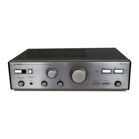
Onkyo A-7 User manual

A-/
ONKYO.
SERVICE
MANUAL
INTEGRATED
STEREO
AMPLIFIER
Model
A-/
SPECIFICATIONS
Model
A-7
Integrated
Stereo
Amplifier
Power
Supply
Rating
Controls
Outputs
Inputs
Dimensions
Weight
AC
120
Volts
60
Hz
(USA
Model)
AC
110V/120V/220V/240V
50Hz/60Hz
(Universal
Model)
POWER
SPEAKERS
(OFF,
A,
B,
A+B)
SELECTOR
(PHONO
1,
PHONO
2,
TUNER,
AUX)
TAPE
MONITOR
(TAPE
1,
SOURCE,
TAPE
2)
Total
Harnomic
Distortion
(AUX)
IM
Distortion
(AUX)
(70Hz
:
7kHz=
4:1)
Frequency
Response
Tilt
Signal
to
Noise
Ratio
Damping
Factor
Rated
input
TAPE
DUBBING
(TAPE
2-1,
OFF,
TAPE
Input
Impedance
1-2)
VOLUME,
BALANCE,
BASS,
TREBLE,
TURN
OVER
SWITCH
BASS
(125Hz,
DEFEAT,
400Hz)
TREBLE
(2kHz,
DEFEAT,
8kHz)
MUTING,
LOUDNESS,
MODE,
HIGH
FILTER,
SUB-SONIC
FILTER
SPEAKER
A
&
B,
PHONES
TAPE
REC
1
&
2,
PRE
OUT
PHONO
1
&
2
TUNER
AUX
TAPE
PLAY
1
&
2
MAIN
IN
17t2''(W)
x
64%4''(H)
x
15"°(D)
444
x
159
x
380
mm
29.7
Ibs.
13.5
kg.
Power
Amplifier
Section
Power
Output
(through
AUX
inputs)
70
watts
per
channel,
min.
RMS,
at
4
Ohms
both
channels
driven,
from
20
Hz
to
20
kHz,
with
no
more
than
0.1%
total
harmonic
distortion.
65
watts
per
channel,
min.
RMS,
at
8
ohms
both
channels
driven,
from
20
Hz
to
20
kHz,
with
no
more
than
0.1%
total
harmonic
distortion.
75
watts
per
channel,
min.
RMS,
at
4
ohms
both
channels
driven,
1
kHz,
0.1%
total
harmonic
distortion.
68
watts
per
channel,
min.
RMS,
at
8
ohms
both
channels
driven,
|
kHz,
0.1%
total
harmonic
distortion.
Load
Impedance
Preamplifier
Section
Input
Sensitivity
&
Impedance
Total
Harmonic
Distortion
IM
Distortion
(70Hz
:
7kKHz
=
4:1)
Frequency
Response
Phono
Overload
Signal
to
Noise
Ratio
Output
Voltage
Output
Impedance
Tone
Control
Turnover
Frequency
Filters
Muting
Loundness
(—40
dB)
BASS
TREBLE
SUBSONIC
HIGH
0.1%
at
rated
power
0.08%
at
1
watt
output
0.1%
at
rated
power
0.08%
at
1
watt
output
2-80,000
Hz
(+1
dB)
better
than
5%
at
50
Hz
110
dB
(IHF
A
NETWORK)
50
at
8
ohms
1.5
volts
100
k-ohms
4—16
ohms
PHONO
1
&
2:
2.5mV,
50
k-ohms
TUNER:
150mV,
50
k-ohms
AUX:
150mV,
50
k-ohms
TAPE
PLAY
1
&
2:
150mV,
50
k-ohms
0.05%
at
rated
output
0.08%
at
rated
output
PHONO:
+0.2
dB
at
30—15,000
Hz
AUX:
+0,
—1
dB
at
10—50,000
Hz
230mV
RMS.
at
1
kHz,
0.1%
THD.
PHONO:
80
dB
(THF
A
NETWORK)
AUX:
90
dB
(IHF
A
NETWORK)
1.5
volts,
max
15
volts
2.7
k-ohms
+10
dB
at
100
Hz
(turnover
at
400
Hz)
+10
dB
at
10
kHz
(turnover
at
2
kHz)
BASS:
400
Hz,
125
Hz
TREBLE:
2
kHz,
8
kHz
10
Hz
(6
dB/oct.)
5
kHz
(6
dB/oct.)
—20dB
.
+5
dB
at'100
Hz
+5
dB
at
10
kHz
Specifications
are
subject
to
change
without
notice.
ONKYO.
AUDIO
COMPONENTS

A-/
SERVICE
PROCEDURES
1.
Checking
the
operation
of
the
protective
circuit.
The
protective
circuit
of
the
A-7
works
in
the
follawing
manner:
A
fuse
burns
out
if
speaker
of
too
low
impedance
are
con-
nected,
or
if
the
speaker
wires
are
accidentally
shorted.
A
relay
cuts-off
output
from
the
amplifier
if
due
to
malfunction
DC
current
appears
at
the
output
terminals.
The
relays
will
also
be
actuated
in
the
event
of
excessive
output
current.
A
check
of
the
protective
circuit
is
made
by
placing
the
unit
in
the
following
sequence
of
settings.
1)
2)
3)
4)
5)
No
load.
Set
all
controls
at
the
levels
set
on
the
power
amplifier
(refer
to
power
amplifier).
Set the
SELECTOR
switch
to
PHONO.
Apply
a
5Hz,
1V
(RMS)
sine
wave
to
the
PHONO
inputs.
Gradually
increase
the
setting
of
the
master
volume
control.
The
protective
circuit
relay
should
activate
as
a
result
of
this.
Note:
Operation
of
tht
protective
circuit
relay
can
also
be
checked
by
setting
the
center
voltage
at
DC
4V
and
removing
the
fuses
F701
and
F702,
and
then
applying
a
DC
+5V
voltage
to
the
output
terminals.
This
should
actuate
the
relay.
2.
1)
2)
3)
4)
Checking
the
circuit
board
of
the
power
amplifier.
Remove
two
lower
screws
from
the
heat
sink.
Remove
two
screws
on
the
back
of
the
heat
sink.
Remove
two
heat-sensor
transistors
Q613
and
Q614
from
the
heat
sink.
If
they
cannot
be
pulled
out,
remove
two
mounting
screws
from
the
transistor
sockets.
The
check
can
also
be
performed
by
fastening
it
as
shown
in
Fig.
1
with
screws
that
have
been
removed.
Screw
Fig.
1
The
screws
used
to
fasten
the
bus
grounding
strips
and
the
terminals
of
the
power
supply
electrolytic
capacitor
have
can
influence
sound
quality.
They
must
be
tightened
securely.
When
replacing
differential
amplifier
or
push-pull
amplifier
transistors,
be
sure
that
transistors
of
both
channels
have
the
the
same
hrg
ratings.

COMPONENT
LOCATION
Tapping
Screw
4STR+12BQ
PARTS
LIST
REF.
NO.
STOCK
NO.
DESCRIPTION
REF.
NO.
STOCK
NO.
DESCRIPTION
l
28184017A
Top
Cover
12
250126
Headphone
Jack
3P64M
2
838440109
Screw
4TTB+10C
(BC)
13
28320155
Knob-Volume
12829121
Front
Panel
Ass'y(3
~
7)
14
28320158
Knob-Selector
3
27210069
Front
Panel
15
28320157
Knob-Level
4
—27265009A
Ring
16
28320161
Knob-Tone
5
27267014
Knob
Guide
17
38320163
Knob-Shift
6
28198502
Facet
18
28320162
Knob-Push
7
27267015
Knob
Guide
19
28320159
Knob-Power
8
27170019
Bottom
Board
20
28320160
Knob-Push
9
280379
Leg
21
838130062
Tapping
Screw
3STBt6BQ
10
831130082
Tapping
Screw
3STW+8BQ
22
270611
Pilot
Lamp
Cover
11
832140122

COMPONENT
LOCATION
21
22
PARTS
LIST
REF.NO.
STOCK
NO.
]
12829576A
2
12829575A
3
12838573
4
128385741
5
128385742
6
2200592
or
2200593
7
2200582
or
2200583
8
27150048
9
230187
10
3504097
11
25035050
12
5104041
13
25030073
14
25055015
15
25045029
16
25045025
17
250170
18
25045022
19
25060008
20
25060023
21
25050004
22
252020
23
3504012
TP
Universal
Model
DESCRIPTION
Main
Amp.
P.C.B.
NAMA-376a
Rectifier/Preamp
P.C.B.
NAAF-375a
Switch
P.C.B.
NATM-373
Treble
Control
P.C.B.
NATS-374
Part
1
Bass
Control
P.C.B.
NATS-
374
Part
2
Power
Amp.
Transistor
28D426
(R)
or
2SD426
(O)
Power
Amp.
Transistor
25B556
{(R)
or
2SB556
(Q)
Shielded
Plate
Power
Transformer
NPT-608D
Elect.
Capacitor
25000uF
55V
Power
Switch
NPS-111-L15P
Variable
Resistor
N35
DGR32C100KT30M,
Volume
Control
Rotary
Switch
NRS-124-30Y,
Speaker
Selector
Connection
Bar
TAPE,
PRE
OUT,
MAIN
IN
Terminal
TUNER/AUX
Input
Terminal
NPJ-4PRBLO03
Phono
Terminal
NTM-2WPBL-E1
Tape
Terminal
NPJ-6PRBLO3
Ground
Terminal
Speaker
System
Terminal
NTM-4PRMNO1
Fuse
Holder
with
Cover
Speaker
Fuse
5A-T
UL
Capacitor
0.01uF
125V
TOP
VIEW
REF.
NO.
STOCK
NO.
24
27160019
25
250249
26
27140122
27
27140123
28
2714008SA
29
27140157
30
25060025
31
27150055
32
27115014A
33
27110031
34
28140024
35
210015A
36
27120069
51
25050015
52
270025
53
253072
54
250080
-35
252049
—
31
a
a
54
51
52
53
2
USA
Model
12
DESCRIPTION
Heat
sink
Power
Transistor
Socket
M-1614
Heatsink
Bracket
Left
Heatsink
Bracket
Right
Transistor
Socket
A
Transistor
Socket
B
7P
Lug
Plate
Shielded
Plate
Side
Bracket
Front
Bracket
Cushion
6.3V
50mA
Power
Indicator
Lamp
Back
Panel
AC
Outlet
NSCT-6P01
Strainrelief
SR-3P4
AC
Cord
AS-UC
AC
Fuse
Holder
S-N1301
AC
Fuse
4A
ST-6
The
Universal
type
differs
from
the
UDN
type
(USA
model)
at
the
following
points.
9
11
23
36
51-55
61
62
63
230188
25035051
3500052
27120071
250186
25050018
252003
Power
Transformer
NPT-608ADGQ
Power
Switch
NPS-]21-L16P
IS
Capacitor
PME271
YSIOCEE
Back
Panel
none
VS
Socket
S-17205-7
3P
Inlet
Fuse
3A-T

MAIN
AMP.
(NAMA-376a)
MAIN
AMP,
PC
BOARD-PARTS
LIST
CIRCUIT
NO.
Q601~Q604
Q605~Q608
Q609.
Q610
Q611,
0612
Q613,
Q614
Q615,
Q616
Q617,
Q618
D601~D604
STOCK
NO.
Transistors
2210754
2210755
7
2211084
2211085
°*
2211032
2211033
°*
9211022
2211023
2210743
2210744
°F
2200364
2200354
Diodes
223105
DESCRIPTION
erent
or
Differential
Amp.
See
SAE
or
Differential
Amp,
A912
ree
Driver
Amp.
25C1885(Q)
:
2§C1885(R)
Driver
Amp.
28094
P
Scat
oO)
Bias
Stabilization
28D358(D)
Complement
2SB528(D)
Complement
181555
BOTTOM
VIEW
CIRCUIT
NO.
L601,
L602
C605,
C606
C619,
C620
C625,
C626
C631,
C632
C633~C636
R607,
R608
R645,
R646
R651,
R652
R657,
R658
R659~R662
STOCK
NO.
Coils
2310601
Capacitors
390480477
352744711
374121045
374121044
352770331
DESCRIPIION
$-1.3B
4.7pF
50
LD
470uF
1€V
EL
O.1uFt10%
50V
DE
O.1uF+
5%
50V
DE
3.3uF
63V
EL
Variable
Resistors
§221008
§221007
Resistors
451630274
48114795
R-HK4.7KB38S
CENTER
VOLTAGE
R-HK2.2F.B3S8
IDLING
CURRENT
2.7
ohm
1W
Metal
0.47
ohm
SW
Cement
NOTES:
When
replacing
differential
amplifier
or
push-pull
amplifier
transistors,
be
sure
that
transistors
of
one
channel
have
the
same
hrg
ratings.
MAIN
AMP.
ALIGNMENT
NOTES:
1,
Set
up
A-7
as
follows:
SELECTOR...
AUX
TONE
SHIFT....
DEFEAT
TONE
&
BALANCE
..,
Center
FILTER/LOUDNESS/DUBBING
..,
OFF
MODE
.,,.STEREO
T.MONITOR
...
SOURCE
SPEAKERS...
OFF
VOLUME
...
Maximum
(0dB)
2.
Adjust
after
switching
on
for
3
minutes,
1.
IDLING
CURRENT
ADJUSTMENT
Connect
the
DC
Voltmeter
between
Ipp
and
V7
terminals.
Adjust
the
Voltage
to
17£2mV
with
R645.
(Left
channel)
Adjust
the
Voltage
to
17£2mV
with
R646,
(Right
channel)
2.
CENTER
VOLTAGE
ADJUSTMENT
Connect
the
DC
Voltmeter
between
Vey
and
E
terminals.
Adjust
the
Voltage
to
0+5mV
with
R607.
(Left
channel)
Adjust
the
Voltage
to
0t5mV
with
R608.
(Right
channel)
CIRCUIT
NO,
R663,
R664
R667,
R668
R671,
R672
STOCK
NO.
Resistors
451630684
451731004
441521014
Themistors
TH601,TH602
4000003
DESCRIPTION
6.8
ohm
]W
10
ohm
2W
100
ohm
1/2W
D-22A
SWITCH
PC
BOARD-PARTS
LIST
Rotary
Switches
NRS-1
44-30ZL
25030069
25030068
25030068
NRS-143-30A
NRS-143-30A
Metal
Metal
Métal
Oxide
Film
SELECTOR
i
5,
3O
DUBBING
MONITOR
TONE
CONTROL
PC
BOARD
—
PARTS
LIST
Capacitors
C403,C404
374122044
O.2uF+5%
SOV
DE
C407,C408
374121144
O,lipFt5S%50V
DE
C409,C410
390882207
22uFt50V
SLD
C413,C414
372328214
820pF*5%50V
ST
Rotary
Variable
Resistors
R40]
5104042
GH30E-196K
x
2
BASS
R413
5104043
GH30E-171K
x
2
TREBLE
Rotary
Switches
$401,S8402
25030072
NRS-143-30ZV
FREQUENCY
SHIFT
Capacitor
a
DE:
Non-Inductive
Polyester
Film
Capacitor.
LD,
SLD:
Low
Leakage
Current
Type
Electrolytic
Capacitor.
ST:
Polystyren
Film
Capacitor.
EL:
Electrolytic
Capacitor.

BOARD
VIEW
EQUALIZER/TONE
AMP.
PC
BOARD
(NAAF-375a)
ee
ae
I
ee
el
CIRCUIT
NO.
STOCK
NO.
DESCRIPTION
EG
eUPMOISERNG,
GESCRIDLON
CIRCUIT
NO.
STOCK
NO.
DESCRIPTION
3210668.
28A841
(GR)
jetta
ae
|
C501,¢502
352782211
|
220uF
SOV.
EL
vaos
gute
HOG,
BAe
poueeam,,
Deot,ps0z
daeois
—
waaso
OTE
ote.
ff
a
Q205,Q206
d51q666
%
IsaRd1
(BL)
Of
Equalizer
Amp.
D701—D704
ae
a
ERD
bt
ae
er
scr
oe
Me
Q207,Q208
3315676
%
Secieal
(pry
Equalizer
Amp.
D705,D706
223802,
181885
C707
352744701
4
7uF
16V
EL
223801
°
10D1
Q209,
Q210
eeeee
or
281318
(Q)
or
Equalizer
Amp.
Resistors
|
2211043
28C1318
(R)
Capacitors
:
5148013
:
$3
211,Q212
2211052
284720
(Q)
eanayeek
peeoas
R305
are
N16RGL250KMN30O,
Variable,
BALANCE
ms
2211053"
SSA720.GR).
OP
ea
ANSE
nee
©303,C304
320480227
2.2uE
—
50V
LD
R503,
R504
441521514
1500hm
1/2W
Metal
Oxide
Film
/.a0
2210665,
=
2SA841
(GR)
C203.C204
4.
R701
441622014
200ohm
1W
Metal
Oxide
Film
Q301-9304
2210666,
=
2SA8d1
(BL)
Differential
Amp
C305,c300,
eS
ey
EE
R711,R712
441623914
3900ohm
1W
Metal
Oxide
Film
2210416
5
2SA726(F)
9.
C211,C212
390883317
330uF
50V.
SLD
R713
441721824
1.8kohm
2W
—
Metal
Oxide
Film
Pi
Geee..
SECC
RS
€213,C214
374124724
4700pF
45%
SOV
DE
Fae
305
374125624
S600pF
+5%
50V
ODE
witches
teehee
<22t0gTee
DSc
lesl
(BE)
c
1
UAEvR:
ou
Gis
eae
$301~$305
25035039
NPS-542-L04
Push
2200663
2S8C1626
(O)
sa
374121534
O.015uF
+5%
SOV
DE
Q501
or
or
Rectifier
C219,
C220
2200664
28C1626
(Y)
C225,
C226
|
Relay
2200673
2SA816
(0)
cia
2.60
390480107
uF
50V.
LD
hiSai
Ores
NRS2P5A-DC12
Q502
or
or
Rectifier
<-
C317,C318
er00aI
A
easly)
C315,C316
352722211
220uF
63V
EL
27300059
Ground
Plate
ee
ae
a
C319,C320
390480477)
4.7uF
SOV
LD
27150049
Shielded
Plate
701~
545.
O.15uF
+10%
sov
DE
OID
ie
0703:
Fs
ae
og
28C828A
(0)
Protector
C321,C322
3741215
u
2210362
2SC828A
(R)
fae
ae
ac
BSCS
AWD:
ene
DE:
Non-Inductive
Polyester
Film
Capacitor.
.
LD,
SLD:
Low
Leakage
Current
Type
Electrolytic
Capacitor.
NOTES:
When
replacing
differential
amplifier
or
push-pull
amplifier
transistors,
be
sure
that
transistors
of
one
channel
have
ST:
Polystyren
Film
Capacitor.
the
same
hg
ratings.
EL:
Electrolytic
Capacitor.

SCHEMATIC
DIAGRAM
8
be
82
C209
47P(K)
FBitn)
GERD
C
rags
R217
R219
100KIG)
3.9K
aaah
Q209,021
a210
Sooo
eiolor(R)
pa
Q204
Q207
0208
25¢
ea
Sat
ERlor
(BL
-
0206
0208
Q212
BABE
enor
iBLI
211,212
2SA7201Q)or
(R)
C335
470P(K)
Ah
|
if
ey
litte)
Lie.
[LE
_
lear
G
Pe.
are
eae
“31
i
|
u
°
|
eee
1
|
uu
fe}
(eo)
7
REC
Cc
;
!
|
hot
[TAPE
Pee
al
ere.
4
Laay
@
0
—
1
4
°
FY
0
|
Oo
on
I
i
%
6
i
ft
a
Te
PREC
B
43
5301
$302
Fs
2
\
age
oo
AR
ek
to
MODE
MUTING
~
PLAY
DUBBING
MONITOR
i
fa.
STEREO
048
t
OFF
{
am.
MONO
=m.
-20
dB
5
TAFE
ce
TAPE
TAPE
a
TAPE-2
1
|
BALANCE
VOLUME
<5
ae
;
one
PLAY
I
Beets
odes
shine
ie
eV
NAUMAN
ie
cctee
o
POWER
ns
i
te
01
NPT~608D
1.0C
VOLTAGES
(([_¥})
ARE
MEASURED
WITH
VT.V.M
TO
CHASSIS
AT
NO
SIGNAL
APPLIED.
2.
UNLESS
OTHERWISE
SPECIFIED:
RESISTORS
ARE
IN
OHMS,
25%,
1/4W.
CAPACITORS
ARE
IN
wF,
SOV.
ELECTROLYTIC
CAPAC
+=
a
creer
net
TTORS
(8)
ARE
IN
pr/WV.
See
rot
[spo
aoe
HBG
A
ar
4.SYMBOL
wLOW
LEAKAGE
CURRENT
TYPE
ELETROLYTIC
CAPACITOR.
4
POLYESTER
FILM
CAPACITOR.
*NON-INOUCTIVE
POLYESTER
FILM
CAPACITOR.
o
POLYSTYREN
FILM
CAPACITOR.
*
@
NON-INFLAMMABL
RESISTOR.
AC
120V
60Hz
THERMO
AC
OUTLETS
HE
RM
FONIVERSAL
TYRE
©
ie
ee
a
F801
110V/120V
SA
$8019
220V/240V
3A
C801
0.017
250V
{mM}
AC
110V/120V
220V
/260V
50/60Hz
C802
Le
ei
2S
et
ee
ee
Se
2017
250V(M)_
NOTICE:
FOR
SOME
SPECIFIC
REGIONS,
THIS
CIRCUIT
IS
CHANGED
FOR
THE
REGIONAL
VOLTAGE
ONLY.
,
ONE
CONTROL
AMPLIFIER
R319
.
33K
R317
100K
100K)
Lazay]
ae
ame,
ma
ee
G,
Reon
6303
R311
C407
"
196K
1
227/50
47K
Paes
6
2209
Kae,
"
O11}
|
6
TREBLE
BASS
ZK)
ane
Reos
3.3K
F20.2v>
|
[2riK1
oa
6h
al
18
18
R25
HRle
}
4
LIKE
FSS!
—
20
A
|
704
—4°
nats
37611)
NATS-374()
|
Q302
|
0304
Q301-Q304
25A841(GR)
or
(BL)
Qos
BSATAIPL
ONG)
7
[NAMA-376a
POWER
AMPLIFIER
2SC1681
R327
|
(GRor
(BL)
727K
|
NE
NR
|
4
24
EIN
BS
R621
10K
aca
Y
|
ae
[oars
a
LMS
C323
33
330P(K}
‘15M
$303
-
$706
LOUDNESS
SUBSONIC
oo.
OFF
OFF
ou
OFF
wh.
ON
ON
ah
ON
wo
|
i
{
i
\
\
i
\
|
j
!
1
|
$305
|
HIGH-CUT
|
|
I
t
\
|
1
1
1
i]
{
OC
POWER
SUPPLY
i
0609.0
‘
06150616
er
SL
57
Pengi2aloriR)
D780)
i
|
Pag
pe
bLRe,
6
refi
Q601-
0604
a60
G66
—
(
Hoey
25C1775A(Djor(E}
yt
ee
ad
=
Dal
sy
SP
OUT
0702
0
eatery
Diorie1
'9003,0004
22
i
a
EY
©
gee
061,612
Apa
‘ooo4]
|
(Ol
or
gb+z
0701-0704
ERO
03-02
or
GP30G
C701~
C704
0.0
1/500
(P}
501
25C1626(O)or
lY)
502
25A816
(OlorlY)
R
1,
BK(2W)
Been
Q704
Baty
2SC1212AWTIC)
af
Cx
0706
2720/6.3
181885
InP}
or
1001
fro
rrr
em
es
ee
ee ee
es
ee
eee
we
ere
cee
ee
ee
ee ee
ee
es
ee
ee
ee
ee
ee
ee
ee
ee
ee
ee
ee
eae
ee
ww
eww
er
ae
eee
©)
LJ
Led
te-J
SPEAKER
-A
SPEAKER
-B
PHONES

PACKING
PROCEDURES
USA
Model
Universal
Model
USA
Model
@
Ali
printed
materials
and
accessory
items
are
placed
in
a
poly
bag
and
taped.
@
The
AC
power
cord
is
wrapped
in
paper
and
wound
with
a
rubber
band.
@
A
tag
describing
the
composition
of
the
cabinet
is
attach-
ed
to
the
speaker
switch.
@
Four
shorting
pins
are
inserted
in
the
phono
terminals.
_
Universal
Model
@
The
AC
power
cord
is
wrapped
in
paper
and
wound
with
a
rubber
band.
@
There
is
a
voltage
tag
to
which
the
unit
is
set
attached
to
the
AC
power
cord.
@
All
printed
materials
and
accessory
items
are
placed
in
a
poly
bag
and
taped.
@
Four
shorting
pins
are
inserted
in
the
phono
terminals.
PARTS
LIST
REF.NO.
STOCK
NO.
DESCRIPTION
REF,
NO.
STOCK
NO.
DESCRIPTION
la
29340193
Instruction
Manual
10
25055018
CV-K-],
Conversion
Plug
lb
29340195
Instruction
Manual
11
290008
500
x
1000
(m/m),
Sheet
2
29358001
Service
Station
List
12
29100027
850
x
650
(m/m),
Poly
Bag
3
29355046
Caution
Card
for
Warranty
Card
13
282969
Caution
Label
A
4
29365003
Warranty
Card
14
293041]
Caution
Label
5
252049
4A,
ST-6,
Fuse
15
29050112
Carton
Box
6
252020
SA-T,
Fuse
16
29090178
Pad,
Left
7
29100006A
250
x
350
(m/m),
Poly
Bag
17
29090179
Pad,
Right
8
253083
Power
Supply
Cord
250153
Shorting
Pin
9
293268
Tag,
Voltage
29380025
Tag,
Cabinet
Composite
19
29100002
150
x
80(m/m),
Poly
Bag
—||]—
Table of contents
Other Onkyo Amplifier manuals

Onkyo
Onkyo TX-844 User manual

Onkyo
Onkyo TX-SV515SPRO User manual

Onkyo
Onkyo TX-SV909PRO User manual

Onkyo
Onkyo A-9000R User manual

Onkyo
Onkyo M-282 - Amplifier User manual

Onkyo
Onkyo A-SV240 User manual

Onkyo
Onkyo TX-SV515PRO II User manual

Onkyo
Onkyo PA-MC5500 User manual

Onkyo
Onkyo P-3099 User manual

Onkyo
Onkyo A-7040 User manual

Onkyo
Onkyo M-508 User manual

Onkyo
Onkyo TX-SV70PRO User manual

Onkyo
Onkyo M-588F User manual

Onkyo
Onkyo TX-SV303Pro User manual

Onkyo
Onkyo A-5VL - Integrated Stereo Amplifier User manual
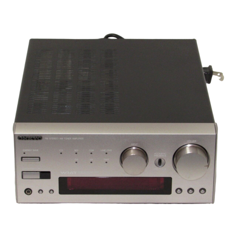
Onkyo
Onkyo FR-155 User manual

Onkyo
Onkyo A-933 User manual

Onkyo
Onkyo MCA1120 User manual

Onkyo
Onkyo DAC-HA200 User manual

Onkyo
Onkyo PA-MC5500 User manual