manuals.online logo
Brands
  1. Home
  2. •
  3. Brands
  4. •
  5. Onkyo
  6. •
  7. Amplifier
  8. •
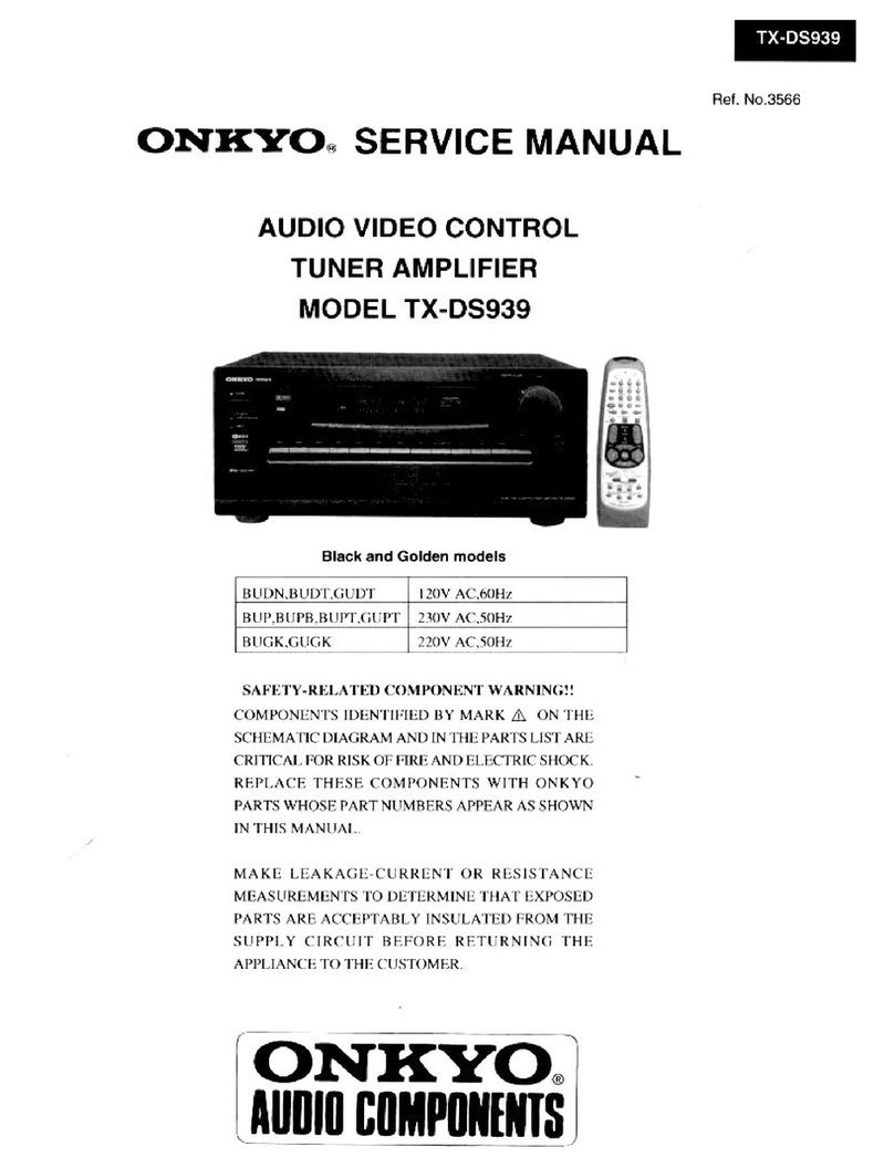
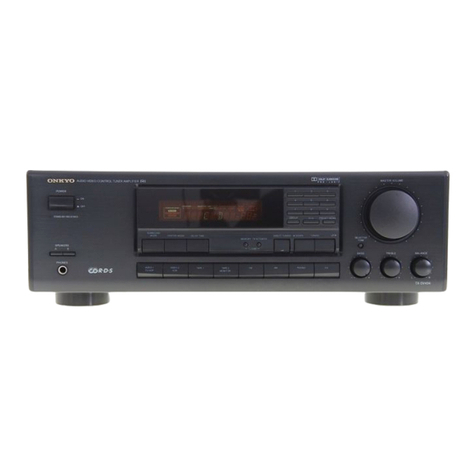
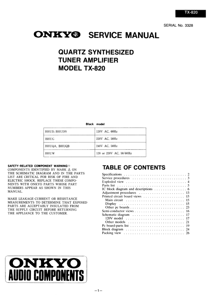
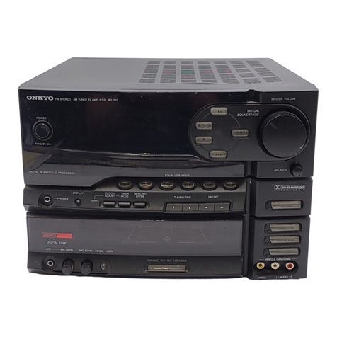
  9. Onkyo TX-7900 User manual

Onkyo TX-7900 User manual

Ref.
No.
3420
ONKYO
SERVICE
MANUAL
QUARTZ
SYNTHESIZED
TUNER
AMPLIFIER
MODEL
TX-7900
MODEL
TX-7920
Black
and
Silver
models
SAFETY-RELATED
COMPONENT
WARNING!
!
COMPONENTS
IDENTIFIED
BY
MARK
A
ON
THE
SCHEMATIC
DIAGRAM
AND
IN
THE
PARTS
LIST
ARE
CRITICAL
FOR
RISK
OF
FIRE
AND
ELECTRIC
SHOCK.
REPLACE
THESE
COMPO-
NENTS
WITH
ONKYO
PARTS
WHOSE
PART
NUMBERS
APPEAR
AS
SHOWN
IN
THIS
MANUAL.
MAKE
LEAKAGE-CURRENT
OR
RESISTANCE
MEASUREMENTS
TO
DETERMINE
THAT
EXPOSED
PARTS
ARE
ACCEPTABLY
INSULATED
FROM
THE
SUPPLY
CIRCUIT
BEFORE
RETURNING
THE
APPLIANCE
TO
THE
CUSTOMER.
ONKYO
AUDIO
COMPONENTS
TABLE
OF
CONTENTS
Specifications
eee
errr
ee
eee
eee
eee
ee
eee
Tee
eee
eee
eee
ere
Terre
ree
eee
ere
2
Service
procedures::+++i+sssssssstssesesesseeesseeseseeseserseeageeens
3
Exploded
view
Model
TX-7920++:+++:+++s+sssesseseseeeeseeessseeneens
4
Parts
Ist
Model
TX-7920
tse:
wvesncwses
ceracmmamninsaeennenee
5
Exploded
view
Model
TX-7900++++++++++:ssess+sessesesseeereeesaeeens
6
Parts
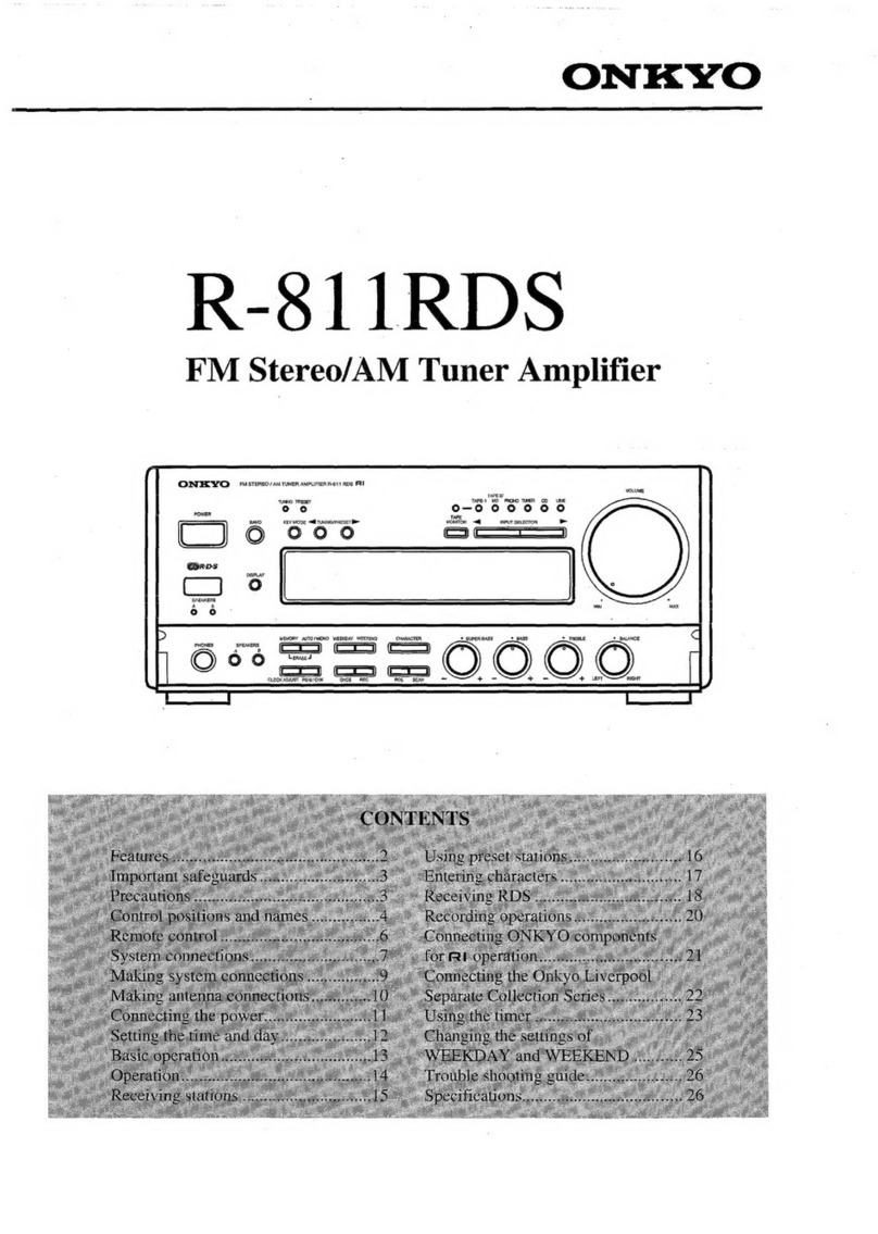
list
Model
‘TX-7900
issssster<eomnns
sane
venwavanes
senna
canon
cones
7
Block
diagram
Model
TX-7920-++++1:+++ssessseerseeesseersese
seeeees
8
Block
diagram
Model
TX-7900-+++++:++1s+sessseerseseseeteseeeeeeeens
9
IC
block
diagram
and
descriptions::::::1++++sseeeseseeseeseerees
10
Packing
view
svrcessscessceeeseeessseeseessenseneeseesesescnesensereanneens
17
Adjustment
procedures
ree
eee
eee
eee
er
errr)
18
Printed
circuit
board
view
from
bottom
side-+r+++++rrr
+
est+*
21
Schematic
diagram
Model
"P7920:
sere:
ose
cwaes
uedewvensaes
eonnenamenaee
eemaseeeninenl
23
Model
TX:
7900»
«sss
sentecnnsaxonenen
nonce
dvtineanennasaerawargicaeenines
25
Printed
circuit
board-parts
list
Model
“TX.
7620
se2nesenses
ary
deanwians
sccswansapanvagis
narangianane
gies
sen
29
Model
1X.
20
0Gxrtceswens
corweswaieaee
dennwonatennigipien
vpeiciirnay
9
tate
wea
39
TX-7900/TX-7920
TX-7900/TX-7920
SPECIFICATIONS
AMPLIFIER
SECTION
Power
Output:
Dynamic
Power
Output:
Continuous
Power
Output:
Total
Harmonic
Distortion:
1M
Distortion:
Damping
Factor:
Frequency
Response:
RIAA
Deviation:
Sensitivity
and
Impedance:
Phono
Overload:
Signal-to-Noise
Ratio:
Tone
Controls:
Muting:
LOUDNESS
(—30dB):
TUNER
SECTION
FM:
Tuning
Range:
TX-7920
60
watts
per
channel,
min.
RMS,
at
8
ohms,
both
channels
driven,
from
40Hz
to
20kHz,
with
no
more
than
0.2%
THD.
2
X
100
watts
at
4
ohms
2
X
75
watts
at
8
ohms
2
X
80
watts
at
4
ohms,
1kHz
(DIN)
2
X
65
watts
at
8
ohms,
1kHz
(DIN)
0.2%
at
rated
power
0.1%
at
30
watt
output
0.2%
at
rated
power
0.1%
at
30
watt
output
50
at
8
ohms
20
—
30,000
Hz
+
1dB
20
—
20,000
Hz
+
0.8dB
Phono:
2.5mV
750
kohms
CD/Tape
Play:
150mV_//50
kohms
Tape
Rec:
150mV//3.5
kohms
120mV
RMS
at
1kHz,
0.2%
TDH
Phono:
80dB
(at
5mV
input,
IHF-A)
CD
/Tape:
100dB
(1HF-A)
Bass:
+
10dB
at
100Hz
Treble:
+
10dB
at
10kHz
—
©
+7dB
at
70Hz,
+5dB
at
10kHz
87.50—108.00MHz
(50kHz
steps)
TX-7900
45
watts
per
channel,
min.
RMS,
at
8
ohms,
both’
channels
driven,
from
40kHz
to
20kHz,
with
no
more
than
0.3%
THD.
2
X
80
watts
at
4
ohms
2
X
60
watts
at
8
ohms
2
X
60
watts
at
4
ohmsm,
1kHz
(DIN)
2
X
50
watts
at
8
ohms,
1kHz
(DIN)
0.3%
at
rated
power
0.1%
at
30
watt
output
0.3%
at
rated
power
0.1%
at
30
watt
output
50
at
8
ohms
20
—
30,000
Hz
+
1dB
20
—
20,000
Hz
+0.8dB
Phono:
2.5mV
7/50
kohms
CD/Tape
Play:
150mV/50
kohms
Tape
Rec:
150mV//3.5
kohms
120mV
RMS
at
1kHz,
0.3%
THD
Phono:
80dB
(at
5mV
input,
|HF-A)
CD/Tape:
100dB
(IHF-A)
Bass:
+
10dB
at
100Hz
Treble:
+
10dB
at
10kHz
+7dB
at
70Hz,
+5dB
at
10kHz
Mono:
12.4dBf,
1.2“V,
750hmd.
1.2”V
(S/N26dB,
40kHz
Devi.)
750hms
DIN
Stereo:
19.2dBf,
25"V,
750hms
25“
(S/N
46dB,
Devi.)
750hms
DIN
Mono:
18.2dBf,
2.2“V,
750hms
Stereo:
38.2dBf,
22“V,
75ohms
Usabls
Sensitivity:
50dB
Quieting
Sensitivity:
Caputure
Ratio:
1.5dB
Image
Rejection
Ratio:
85dB
IF
Rejection
Ratio:
90dB
Signal-to-Noise
Ratio:
Mono:
70dB
Sterep:
65dB
Stereo:
65dB
Selectivity:
50dB
DIN
(+300kHz,
40kHz
dev.)
AM
suppression
Ratio:
50dB
Harmonic
Distortion:
Mono:
0.15%
Stereo:
0.30%
30—15,000H2+1.5dB
40dB
at
1kHz
30dB
at
100—10,000Hz
17.2dBf,
44¢V
Frequency
Response:
Stereo
Separation:
Muting
Level:
AM:
Tuning
Range:
522—1610kHz
(9kHz
steps)
522—1610kHz
(9kHz
steps)
or
530—1710kHz
(10kHz
steps)
(World
wide
model)
Usable
Sensitivity:
30nV
image
Rejection
Ratio:
40dB
{IF
Rejection
Ratio:
40dB
Signal-to-Noise
Ratio:
40dB
Harmonic
Distortion:
0.8%
GENERAL
TX-7920
TX-7900
Dimensions
(WXHXD):
455
120X316mm
455X120X316mm
17-15/16"
X4-6/8"
12-716"
17-15/16"
X4-6,8"
X12-7//16"
Weight:
8.0kg,
17.6
Ibs.
7.2kg,
15.9
lbs.
1p
Cracleeyap
racy
Ae)
Remote
control
transmitter
RC-223S
(Only
Model
TX-7920)
Transmitter:
Infrared
Signal
range:
Approx.
5
meters
(16ft.
X
4”
)
Power
supply:
Two
“AA”
batteries(1.5V
X
2)
Specifications
and
features
are
subject
to
change
without
notice.
SERVICE
PROCEDURES
1.Replacing
the
fuses
4.Memroy
preservation
For
continued
protection
against
fire
hazard,replace
This
unit
does
not
require
memory
preservation
batteries.
only
with
same
type
and
same
rating
fuse.
A
built-in
memory
power
back-up
system
preserves
contents
Circuit
No.
Part
No.
Description
Model
of
the
memory
during
power
failures
and
even
when
the
:
7
unit
is
unplugged.
The
unit
must
be
plugged
in
and
the
Foz
pa
ese
Eee
SCE
power
switch
turned
on
and
off
once
im
order
to
charge
the
F902
252075
2.5A-SE-EAK,
Primary
TX-7920
back-up
system.
Note
that
since
this
is
not
a
permanent
F951
252074
2A-SE-EAK,AC
outlet
TX-7920
memory,the
power
switch
must
be
turned
on
and
off
a
few
times
each
month
to
keep
the
back-up
system
operative.
2.Safety-check
out
The
period
of
time
during
which
memory
contents
are
After
correcting
the
original
service
problem,perform
preserved
after
power
has
last
been
turned
off
varies
the
following
safety
check
before
releasing
the
set
to
depending
on
climate
and
placement
of
the
unit.
the
customer.
On
the
average,
memory
contents
are
protected
over
a
Connect
the
insulating-resistance
tester
between
the
period
of
3
to
4
weeks
(a
minimum
of
2
weeks)
after
plug
of
power
suuply
cord
and
nickel
screw
on
the
back
the
last
time
power
has
been
turned
off.
This
period
is
panel.
shorter
when
the
unit
is
exposed
to
very
high
humidity
or
Specifications:
More
than
10M
0
used
in
an
area
with
an
extremely
humid
climate.
3.Changing
the
band
step
A
BAND
STEP
selector
switch
is
not
provided.
R707
85
TX-7920
EXPLODED
VIEW
MODEL
TX-7920
PARTS
LIST
REF.NO.
PARTNO.
DESCRIPTION
REFNO.
PART
NO.
DESCRIPTION
1
27110680Y
Front
bracket
<B>
87
2832A1T1Y
Knob
SP
B
<B>
27110681Y
Front
bracket
<S>
28324173Y
Knob
SP
B
<S>
4
28133254Y¥
Back
plate
91
27300833
WS-2NS,Clamp
5
27100228Y
Chassis
F902
252075
A\
2.5A-SE-EAK
Fuse
6
27160293Y
Radiator
F951
252074
A
2A-SE-EAK,Fuse
7
27141441Y
Bracket
LH
P901
253164Y
or
A
AS-CEE,
8
27141442Y
Bracket
RH
253175Y
Power
supply
cord
9
27141443Y
Bracket
PC
Q503,Q504
2202282,
2SA1265N-R,
12
27130643AY
Bracket,shield
2202283,
2SA1265N-0,
13
27121535-2Y
Back
panel
2201693,
2SA1491-0,
14
27300750
A
Bushing
2201694
or
2SA1491-Y
or
16
27190524
KGLS-14R,Holder
2201696
2SA1491-P,Power
amplifier
transistor
17
27190266
KGLS-12R,Holder
Q505,Q506
2202292,
2SC3182N-R,
21
834430088
3TTS+8B(BC),Self-tapping
screw
2202293,
2SC3182N-0,
22
831130088
3TTW+8B,Self-tapping
screw
2201703,
2S8C3855-O,
23
830440089
4TTC+8C(BC),Self-tapping
screw
2201704
or
2SC3855-Y
or
24
833430080
3TTP+8P(BC),Self-tapping
screw
2201706
2SC3855-P,Power
amplifier
transistor
25
82143006
3P+6FN(BC),Pan
head
screw
T901
2300754Y
A
NPT-1129P,Power
transformer
26
801433
3SMS10W.SW+14B(BC),Sems
Ul
1A331525-1A
NARF-4325-1A,Tuner
circuit
pe
board
|
self-tapping
screw
ass'y
oa
31
28184471AY
Top
cover
U2
1A331526-1A
NADIS-4326-1A,Display
circuit
pe
|
32
834430088
3TTS+8B(BC),Self-tapping
screw
board
ass'y
33
28140680
0.5
X
180
X8,Cushion
U3
1A331527-1A
NAAF-4327-1A,Power
amplifier
circuit
34
27270212
Spacer
<P/W/Q>
pe
board
ass’y
51
1A333701K
Front
panel
ass'y
<B>
U4
1A331528-1A
NASW-4328-1A,Headphone
terminal
1A334701K
Front
panel
ass'y
<S>
pe
board
ass'y
52
28125226BY
End
cap
L
US
1A331529-1
NASW-4329-1,Power
switch
pc
board
53
28125227BY
End
cap
R
ass'y
58
28191617Y
Clear
plate
U6
1A331530-1
NAETC-4330-1,Terminal
pe
board
ass'y
59
833430080
3TTP+8P(BC),Self-tapping
screw
U7
1A331531-1A
NAPS-4331-1A,Power
supply
circuit
60
28135199
Badge
pe
board
ass'y
61
27175254
Leg
U9
1A331533-1
NAETC-4333-1,AC
outlet
pe
board
62
834430088
3TTS+8B(BC),Self-tapping
screw
ass'y
71
25060044
Terminal
GND
U10
1A331534-1A
NAAF-4334-1A,Tone
control
circuit
81
28324162Y
Knob
LOUD
<B>
pe
board
ass'y
28324177Y
Knob
LOUD
<S>
Uli
1A331535-1
NAETC-4335-1,
Volume
control
pe
NOTE:
<B>:Black
model
only
82
28324150-1Y
Knob
LEV
<B>
board
ass'y
<S>:Silver
model
only
28324151
Knob
LEV
<S>
U12
1A331537-1
NAETC-4337-1,Terminal
pe
board
ass'y
83
28324163
Knob
VOL
<B>
aadcke
Ener
SS
:
THE
COMPONENTS
IDENTIFIED
BY
MARK
A
&
saeco
Sega
ARE
CRITICAL
FOR
RISK
OF
FIRE
AND
28324184
Knob
POW
<S>
ELECTRIC
SHOCK.
REPLACE
ONLY
WITH
86
28324170Y
Knob
SP
A
<B>
PART
NUMBER
SPECIFIED.
28324172Y
Knob
SP
A
<S>
4
ios
“I
oO
N
oO
TX-7900
EXPLODED
VIEW
MODEL
TX-7900
PARTS
LIST
REF.NO.
1
12
13
14
16
17
21
22
23
25
26
31
32
33
34
31
52
33
38
59
61
62
71
81
82
83
85
PART
NO.
27110680Y
27110681Y
28133255Y
27100228Y
27160290Y
or
27160272AY
27141441Y
27141442Y
27130643AY
27121536-2Y
27300750
27190524
27190266
834430088
831130088
830440089
833430080
82143006
801433
28184471AY
834430088
28140680
27270212
1A337701K
1A338701K
28125226BY
28125227BY
28191617Y
833430080
28135199
27175254
834430088
25060044
28324162Y
28324177Y
28324150-1Y
28324151
28324181
28324182
28324140
28324184
DESCRIPTION
Front
bracket
<B>
Front
bracket
<S>
Back
plate
Chassis
Radiator
Bracket
LH
Bracket
RH
Bracket,shield
Back
panel
A
Bushing
KGLS-14R,Holder
KGLS-12R,Holder
3TTS+8B(BC),Self-tapping
screw
3TTW+8B,Self-tapping
screw
4TTC+8C(BC),Self-tapping
screw
3TTP+8P(BC),Self-tapping
screw
3P+6FN(BC),Pan
head
screw
3SMS10W.SW+14B(BC),Sems
self-tapping
screw
Top
cover
3TTS+8B(BC),Self-tapping
screw
0.5
X
180
X8,Cushion
Spacer
Front
panel
ass'y
<B>
Front
panel
ass'y
<S>
End
cap
L
End
capR
Clear
plate
3TTP+8P(BC),Self-tapping
screw
Badge
Leg
3TTS+8B(BC),Self-tapping
screw
Terminal
GND
Knob
LOUD
<B>
Knob
LOUD
<S>
Knob
LEV
<B>
Knob
LEV
<S>
Knob
VOL
<B>
Knob
VOL
<S>
Knob
POW
<B>
Knob
POW
<S>
REF.NO.
86
87
91
F902
P901
Q503,Q504
Q505,Q506
T901
Ul
U2
U3
U4
U6
UT
U10
U12
PART
NO.
28324170Y
28324172Y
28324171
28324173Y
27300833
252074
253164Y
or
253175Y
2202492,
2202493,
2202243,
2202244
or
2202246
2202502,
2202503,
2202253,
2202254
or
2202256
2300758Y
1A335525-2A
1A335526-2A
1A335527-2A
1A335528-2A
1A335530-2
1A335531-2A
1A335536-1A
1A335537-2
DESCRIPTION
Knob
SP
A
<B>
Knob
SP
A
<S>
Knob
SP
B
<B>
Knob
SP
B
<S>
WS-2NS,Clamp
ZA
2A-SE-EAK,
Fuse
A
AS-CEE,
Power
supply
cord
2SA1264N-R,
2SA1264N-O,
2SA1694-O,
2SA1694-Y
or
2SA1694-P,Power
amplifier
transistor
2SC3181N-R,
2SC3181N-O,
2SC4467-0,
2S8C4467-Y
or
2SC4467-P,Power
amplifier
transistor
A
NPT-1130P,Power
transformer
NARF-4325-2A,
Tuner
circuit
pc
board
ass'y
NADIS-4326-2A,Display
circuit
pe
board
ass'y
NAAF-4327-2A,Power
amplifier
circuit
pe
board
ass'y
NASW-4328-2A,Headphone
terminal
pe
board
ass'y
NAETC-4330-2,Terminal
pc
board
ass'y
NAPS-4331-2A,Power
supply
circuit
pe
board
ass'y
NAAF-4336-1A,Tone
control
circuit
pe
board
ass'y
NAETC-4337-2,Terminal
pc
board
ass'y
NOTE:
<B>:Black
model
only
<S>:Silver
model
only
NOTE:
THE
COMPONENTS
IDENTIFIED
BY
MARK
A.
ARE
CRITICAL
FOR
RISK
OF
FIRE
AND
ELECTRIC
SHOCK.
REPLACE
ONLY
WITH
PART
NUMBER
SPECIFIED.
+
a
~sJ
oO
Oo
1)
BLOCK
DIAGRAM
MODEL
TX-7920
wal
2
Be
2
ieee
|
Ze
t
i
i
$
TRI
TR2
TI
ator.
aioz
aio4
Cie
ete
veg
RF
AMP
aie
et
TY
FM
IF
FM
IF
&
AM
RADIO
SYSTEM
z
2
LAI266
AN7470
z
w
f
:
:
=
fais
152,
XII
2
2
*
AG.c
SW
AM
IFT
5
TUOO!
TRS.TR5
=
lem
FRONT
END
[FM
LOCAL
C)
Y
osc
oO
|
||
_
1
S801
oy
i
hi
ie
O
F902
Pow!
&
CONTROLLER
6801
O
LM7OO!
+81
PRIMARY
aa:
{
g
FUSE
~B2]
9903
?
REGULATOR
d
+5v
[0902
;
F95I
cog
REGULATOR
ed
H
AC
¥
OUTLET
py
PO7S268CW
-025
+12v
Tasor
T901
Q30i
Pa
peo2~5
Rg
REGULATOR!
RL9O1
EQUALIZER
o
es
>
z
<
=
AC
OUTLET
>
5
NPT-!129P
-
a
ce
om
Ww
»
RI
IN/OUT
x702
Q705
rec
©
be
&
BUFFER
»
=
=
PLAYG
9
|
|
i
U7O1
Q703
Q555
=
REMOTE
ICODE
CHANGE
wi
GATE
rec
©
=
i
SENSOR
Poi7ioscx
|
5
einer
Q553.554
TAPE
2
Sani
2
ORIVE
8
a
PLAY
@
VOLUME
ba
al
<
OTOR
DRIVER]
|Q5!5
.
GATE
Bs
ANALOG
SW
CIRCUIT
z
PS5I
LC7823
SPEAKER
(M)
+8
TERMINAL
Q4ol
[
te
R453
|
x
C)
$
w
Le
ae
RLS55I
_
R45
SPEAKER
F
weg
MASTER
MUTE
RELAY
25
b
VOLUME
sw
t
417
TREBLE
()
S
—
z
on
R421
BAS
a
aan
ay
TO
RCH
:
S451
Q517
HP
TERMINAL
BUFFER
LOUDNESS
O¢C6ZL-X1L
MODEL
TX-7900
L101,
L102
FM
IFT
AM
OUT
L201
a
Z
S
———
ae
aa
7
Eo
z
§
:
8
Wi
aia.
102
alos
LIo3
201
ak
e
FM
IF
FM
iF
&
AM
RADIO
SYSTEM
BIRDIE
STEREO
DECODER
weg
&
nz02
<2
AMP
hae
GATE
z
ra
LAI2z66
FILTER
AN7470
“a
CIRCUIT
HL
|
5
i
3
5
2
=
2
Lis!
(Lis2,xisi
C
)
3
2
J
laos
List
152,
.
)
AG.C
SW
BLOCK
AM
IFT
5
TR4.TRS
=
FM
LOCAL
@
ost
Qi3s
AM+B
-
Qi32
a133
O
$90!
L.P.F.
fe
ae
SYNTHESIZER
43
i
F902
POWER
Sw
&
CONTROLLER
o_o
Eis
eee
BOA
?
FUSE
=
al
5
~82[Q903
?
Rie
FS
REGULATOR
©
9
9
02
:
]
a
a
ee
ee
ST
=“
ii}
i
Set
EOULATOR
Za
2
T901
NPT—1130P
a
=
ppo7sz6scw-025
|
+i2v
Posoa
3
EQUALIZER
|
|
REGULATOR
PHONO
&
Be
e
x70
|
uw
REC
GQ
i
~
[4
PLaY@®
a
bE
fe
Z
x
w
GATE
S
on
rec
@
|
5
CIRCUIT
553.554
=
RELAY
TA
PE
2
4
DRIVE
PLaY@
¥
ois
Q551.552
GATE
z
CIRCUIT O¢:"DET
°
1.
3
PSsi
aj
SPEAKER
+8
wo
«BL
TERMINAL
Q4ol
$
393
S30
Ls
oO
di
%
A
uw
RLSSI
.
8
P
as5i3
z
R459
we]
MASTER
AUDIO
ares
i
®
°
Oa
VOLUME
=
wuUTE
ga
R47
TREBLE
CQ
i
R421
BASS
Oo
>
accel
P6Ol
To
RCH
$451
Q517
©
HP
TERMINAL
LOUONESS
BUFFER
4
is
ba
|
©
o)
o)
TX-7900/TX-7920
IC
BLOCK
DIAGRAM
AND
DESCRIPTION
LM7001(PLL
synthesizer
and
controller)
Phase
Detector
Charge
Pump
.
Divider
=]
-
|
Shift
Register
Latch
aoe
Latch
31
CE
te
athe
~10—
Pin
No.
|
Terminal
Description
1
XOUT
Connect
to
the
7.2
MHz
crystal
oscillator.
3
CE
Chip
enable
terminal.
Connect
to
the
PLL
terminal
of
micro
processor.
4
CL
Serial
clock
input
terminal.
Connect
to
the
CLOCK
terminal
of
micro
processor.
5
DATA
|
Serial
data
input
terminal.
Connect
to
the
DATA
terminal
of
micro
processor.
6
SYN
Not
used.
é
[
7
AUTO/MONO|
Auto/Mono
control
output
terminal.
“H”
when
Auto.
8
BO2
FM
control
signal
output
terminal.
““L”
when
FM.
1
L
9
|
BO3
|
AM
control
signal
output
terminal.
““L”
when
AM.
10
AMIN
AM
local
oscillator
input
terminal.
11
FMIN
|
FM
local
oscillator
terminal.
7
L
12
Vop
1
|
Power
supply
terminal
for
back-up.
13
Vopp2
Power
supply
terminal.
14
PD1
Charge
pump
output
of
the
phase
detector
which
constitutes
the
PLL.
High
level
is
output
when
sl
divided
local
oscillator
frequency
is
high
than
the
reference
frequency.
15
PD2
In
the
opposite
case,
low
level
is
output.
Floating
occurs
when
the
frequencies
matched.
The
output
is
applied
to
the
variable
capacitor
diode
in
the
local
oscillator
through
the
low
pass
|
filters.
16
Vss
Ground
terminal.
TX-7920
4
PD17103CX-528(Remote
control
decoder)
MODEL
TX-7920
|
Transminer|
AM
Bus
line
Q703
Remote
control
decoder
Infrared
XIN
GND
X
OUT
POB2
—
STAND-BY
RESET
POB1
—
RECEIVE
REMIN
—
PODO
POBO
—
VOL
IND
PH
SENS —
POD1
POC3
—
VOL
UP
POWER
—
POD2
POC2
—
VOL
DOWN
SYSIN
—
POD3
110]
POC1
—
PHONO
VDD
|
9
|
POCO
—
SYS
OUT
Terminal
Description
;
1
[xn
|
OSC
Connect
to
the
8.00MHz
ceramic
oscillator
System
reset
terminal.
Active
low.
Signal
input
terminal
from
preamp.
for
remote
control.
Active
low.
IN
Phono
detection
input
terminal.
Active
low.
w
is]
ie)
g
~
x
aide
3/715
Stand-by
detection
input
terminal.
During
low
input,
only
the
POWER
code
is
decoded
7
POD3
YS
IN
System
code
input
terminal
Power
supply
terminal.
Output
at
this
terminal
are
the
custom
code
(16bits)
remote
control
code
input
to
REMOTE
IN,
data
code
(8bits),
and
the
serial
code
(12bits)
that
has
been
converted
corresponding
to
the
decoded
data
code
(8bits)
When
the
player
PLAY/REEJECT
is
input,
a
high
pulse
of
200ms
is
output.
SYS
OUT
PHONO
VOL
DOWN
When
the
volume
DOWN
code
is
input,
a
high
pulse
of
120ms
is
output.
VOL
UP
VOLIND
o
a
e)
=
tr
vs)
When
the
volume
UP
code
is
input,
a
high
pulse
of
120ms
is
output.
POBO
|
VOL
IND
During
the
output
of
VOLUME
UP/DOWN,
a
pulse
([T
LT
JT
LTJ=
250ms)
is
output.
(Not
used.)
POB1
|
RECEI
This
is
the
display
output
for
remote
control
reception.
Output
is
low
when
decoded
code
is
being
recieved.
POB2
“BY
STAND-BY
indication
terminal.
[16
[Va
[GND
—W-
#PD75268CW-025(Microprocessor)
FL
TUBE
CLASS
SCAN}
DIRECT
8
7
4
3
|
up
|
DowN
|MuTE/mooe|
MEMORY
|
|_rM
|
am
|
cLass-F
|
cLAss-€
cD
TAPE-|!
TAPE-2
S.TONE
SLEEP
POWER
N
PROTECT
TO
MUTING
SW_OF
TU
MUT
TUNER
TO
MUTING
SW
OF
PRE
3D.
OISE
0
LY)
RELAY
OUT
Q133
PLL
SYNTHESIZER
ANO
CONTROLLER
RESET
preset
LRESET
AMIOK
BANDI
BANDO
xT2
xT
I
Region
[Range
space
|
Europe
_
|87.50-108.00MHz
|SOkEiz
SOkHz
100kHz
o
=
baat
|
i<e)
=)
i=)
~
+
~~
ce)
iywd
Oo
|
=
wo
|
TERMINAL
DESCRIPTION
sa
ppage
of
electric
current.
SYS
OUT/
{System
code
output
terminal."L"when
active.
SYS
EN
Initializing
input
terminal
when
the
power
turns
on.
a
"L"
when
stereo
broadcast.
|
9
|sysIN
|
System
code
input
terminal."H"
when
active.
Broadcast
detection
input
terminal."L"
when
active.
Control
the
stop
of
auto
tuning
and
output
TU
MUT(#19).
NOISE
_
[Noise
detection
input
terminal.Not
used.
|
12
[PROTECT
PHONO
|
Notused,
tt
C(‘“‘“‘CSOC*C*C‘*zC
|
17.
{MODE
|
Initializing
input
terminal
for
operation
mode
setting.
Speaker
relay
control
output
terminal.
Key
scan
input
terminals.
"H"
when
active.
Connect
to
the
terminal
CE
of
PLL
IC
(LM7001
0133).
Connect
to
the
terminal
CL
of
PLL
IC
and
analogue
switch.
Connect
to
the
terminals
DATA
of
PLL
IC
and
analogue
switch.
SEL
Analog
switch
control
output
terminal.
Connect
to
the
terminal
SEL
of
analogue
switch
7823
Q324
31
Connect
to
the
4.19MHz
ceramic
oscillator.
Ceramic
oscillator
connection
terminal
for
sub
system
clock.
|
34
s[xT2
Not
used.
Initializing
input
terminal
for
region
setting
of
FM
band.
|
48
p49
|
|Notused
|
50
{sn
[51
Isms
Segment
output
terminals."H"
when
active.
|
52
isi
53
S.TONE
_|SELECTIVE
TONE
control
output
terminal.Not
used.
|
59
isi
|
60
{sh
|
Segment
and
key
scan
output
terminals.
|
61
|ss
|
"H"
when
active.
|
2
ise
|
63
ise
|
64__|vDD
__[Powersupplyterminal(+5V)
_
ce
om]
<e)
So
oO
~
+
ie
~
ice)
N
oS
TX-7900/TX-7920
LA1266(FM
IF
and
AM
radio
system)
Fa
1F
IF
AMP
IF
10.
7MHz
am
us
ae
be
iF
IN
STOP
ouT
IN
Yee
———
1
2
———
—_—_—.
a
a
—_—
——
1
|
i
I
F
IF
NATE:
aie
OsT
FM
IF
AMP
aaa
—o—12
FM
BUEEES
BUFFER|_
DETECTOR
AMP
OUT
T
zi
H
H
1
i
Ss
At
IF
18——~
98
IN
{
CURVE
AM
IF
|
20
—
our
|
al
RF
im
NARROW
|
LED
AM
OSC
BUFFER
REG
Ss
A.
G.
C 8
METER
METER
DRIVER
|
q
|
|
$e
|
Gene
|
Jee
|
7
'
|
—
15
aN
cine
OUT
Osc
GND
*
f
ouT
AN7470(Stereo
decoder)
115
|
————
PHASE
PILOT
STEREO
SW
a
76
k
PRESENCE
DETECTOR
Hz
DAIVe
*
eh
J
a
er
ey
To
i
bivicen
ed
piviDeR
yA
it
ne
oIviDeR
STEREO
LB1630(Motor
driver)
(MODEL
TX-7920)
Voutl
Vout2
TRUTH
TABLE
~14—
TX-7900/TX-7920
FIPSBTM8(Fluorescent
tube)
FM
Stereo
Indicator
Tape-2
Monitor
Indicator
Tuned
Indicators
Memory
Indicator
FM
Muting
On/Off
indicator
Y
emony
1
aupio
mute
‘ae
HT
Ra
enim
PL
ae
‘CT
es
D2;
D1
Preset
Station
Display
Audio
Muting
Indicator
(TX-902
only)
APR
RF
STEREO
MODE MODE
os
APR
system
indicators
Classified
Memory
Display
coe
TX-7900/TX-7920
LC7823/LC7823N(Analog
switch)
Lto
j
=
oo
|
oR!
vel
gg
[Fg
bon
Lcomt
0
;
©
RCOMI
Serial
Data
Composition
uot
—g
Same
le
=
|
pe}
[iT
dt
i
ae
-
|
asi0_|
LC7823-N
Polat
sr
re
ee
fee
TT)
swrcncimenovn
SIE
Coot
fan
Th
tea
ba]
—,,
|
coe
HIT
Lacon
|
o693
|
ucreaan
|
of
of
s
[1]
vey
Ba
—
hte
|
604
|
crn
|i
fol
i
fi]
rooms
|
HTT
okeome
ADDRESS
00
==
LEV
SHIFT
er
fee srt
|
|
vee
fal
——s
3
ql
|
2.04
C?
«
Res
>
SHFT
REGSTER
F
<i
|
oes
[5,26
[TAPE-1
PB
LCOM2,RCOM2
Off
when
the
input
selector
is
TAPE-2.
TAPE-2
PB
On
when
the
input
selector
is
TAPE-2.
LCOM3,RCOM3
{Common
terminal.
LCOM4,RCOM4
Negative
power
supply
terminal.(-15V)
Chip
enable
terminal.Connect
to
the
terminal
FUNC
of
the
microprocessor.
|
wu
|p
|
Serial
data
input
terminal.Connect
to
the
terminal
DATA
of
the
microprocessor.
Serial
clock
terminal.Connect
to
the
terminal
CL
of
the
microprocessor.
[16
[Vss_
|
Ground
terminal.
Select
terminal.
|
18
|RES
{Reset
terminal.
[19
[VDD
__|
Power
supply
terminal.(45V
4
PC1225H(Power
amplifier
driver)
NJM4558D-X(Operation
amplifier)
—~16—
PACKING
VIEW
TX-7920
REF.NO.
PART
NO.
1
29052331
Y
29052332Y
29091440AY
29091441AY
29100034A
282301
29110071
261504
Accessary
bag
ass'y
29341685Y
29100097
292112Y
232140
29365020E
29100094A.
3010165Y
24140223Y
2010200
oI
nn
&
WwW
WV
DESCIRPION
Master
carton
box
<B>
Master
carton
box
<S>
Pad
L
Pad
R
850
X650,Styrene
bag
Sealing
hook
Damplon
tape
Adhesive
tape
Instruction
manual
350
X
250,Styrene
bag
FM
antenna
NMA-3057,AM
loop
antenna
Warranty
card
Styrene
bag
for
warranty
card
UM-3,Two
batteries
RC-223S,Remote
control
unit
Cord
RI
-~17—-
TX-7900
REF.NO.
2
3
4
5
6
7
8
NOTE:
TX-7900/TX-7920
PART
NO.
DESCIRPION
29052334Y
Master
carton
box
<B>
29052335Y
Master
carton
box
<S>
29091440AY
Pad
L
29091441AY
Pad
R
29100034A
850
X650,Styrene
bag
282301
Sealing
hook
29110071
Damplon
tape
261504
Adhesive
tape
Accessary
bag
ass'y
29341685Y
Instruction
manual
29100097
350
X250,Styrene
bag
292112Y
FM
antenna
232140
NMA-3057,AM
loop
antenna
29365020E
Warranty
card
291000944
Styrene
bag
for
warranty
card
<B>:Black
model
only
<S>:Silver
model
only
TX-7900/TX-7920
ADJUSTMENT
PROCEDURES
Preparation
1.Input
FM
mono:1kHz,75kHz
devi.,60dB/
»
V
FM
stereo:
1kHz,75kHz
devi.,60dB/
nu
V
Pilot
signal
19kHz
7.5kHz
devi.
AM:400Hz
30%
mod.
2.Outputs
Connect
the
non-inductive
type
resistors
of
8
ohms
to
the
speaker
terminals
A
unless
otherwise
noted.
3.Standard
Knob
Position
VOLUME
ii
vtisdessscssescdsescsseessenveas
Maximum
BASS/TREBLE/BALANCE............
Center
MUTING/LOUDNES.G..................
Off
INPUT
SELECTOR...................06
CD
SPEAKERS...
ccc
cecceeseceeseceneees
A
Confirming
Operation
1.Protection
circuit
a.
Speaker
relay
The
speaker
relay
turns
on
after
the
power
switch
turned
on
for
5
minutes.
The
speaker
relay
turns
off
immediately
after
the
power
switch
turns
off.
b.
Over-voltage
confirmation
The
speaker
relay
is
off
immeditely
after
DC
voltage
+
6V
is
applied
to
the
terminal
CD.
Amplifier
section
Idling
Current
Adjustment
Connect
the
DC
voltmeter
to
the
terminals
LID(RID)
and
CT
on
the
power
amplifier
pc
board.
Adjust
the
semi-fixed
resistor
R511(R512)
so
that
the
indication
of
voltmeter
is
5+0.5mV.
Note:(_
):Right
channel
R512
=)
9S
R511
o
LID
0
VCT
RID
o
VCT
o
—~18—
POWER
AMPLIFIER
PC
BOARD
SOLDERING
SID!
FM
section
Item
Step
|
Connection
of
FM
SG
output
Stereo
modu-
Tuned
Output
indicator
Adjustment
Adjust
for
Remarks
instrument
lator
output
frequency
point
DC
voltmeter
L101
0+20mV
Set the
FM
mode
99.1MHz
switch
to
MONO.
Repeat
Fig.
1
1kHz,75kHz
devi.
99.1MHz
the
steps
1
and
2
util
65dBf(60dB)
Distortion
L102
no
further
adjustment
analyzer
in
necessary.
a
SS
ew
:
2
=
1kHz,75kHz
devi.
99.1MHz
R201
19kHz+10Hz
Distortion
IF
on
99.1MHz
analyzer
front
end
65d
Bf(60dB)
Lech.
1kHz
Rch.
AC
voltmeter
99.1MHz
R202
Rch.
1kHz
Lch.
AC
voltmeter
99.1IMHz
switch
to
AUTO.
99.1MHz
Ext.
modulation
65d
Bf(60dB)
99.1MHz
Ext.
modulation
65d
Bf(60dB)
99.1MHz
1kHz,
75kHz
devi.
17.
2dBéf
(12dB)
Maximum
and
same
separation
Tuned
TUNED
indicator
R101
99.
1MHz
1kHz,
75kHz
devi.
16.
2dBf£
(11dB)
indicator
level
AM
section
Step
AM
SG
output
1
522kHz
|Digital
DC
|
OSC
coil
—‘|1.5V+0.1V
Reference
specifications
.
voltmeter
on
RF
block
Tuned
voltage
AM_
522kHz
1.5
+0.4V
(L151)
(Connet
Digital
1611kHz
7.5
+0.5V
DC
voltmeter
to
FM
87.50MHz
2.0
+0.5V
603kHz,60dB/m
|
603kHz
AC
RF
coil
test
point
TP-6)
108.0MHz
7.5
+0.5V
on
RF
block
400Hz
30%
mod.
voltmeter
(L151)
Muting
width
35
+
10kHz
990kHz,
60dB/m
990kHz
ae
400Hz
30%
mod.
Sal
nebeE
AM
signal
generator
Output
terminal
antenna
terminal
AM
AM
AM
LOOP
TpP-6
E
LOOP
antenna
Digital
oc
voltmeter
—~19—
Muting
level
FM
12
+
3dB
Auto
stop
level
AM
Less
than
68dB/m
FM
Less
than
20dBu
Stereo
indicator
level
14
+
4dBu
TX-7900/TX-7920
OUTPUT
terminal
FM
signal
Distortion
generator
analyzer
Antenna
Terminals
terminal
Tp
TP-2
oc
voltmeter
(Fig.
1)
Antenna
terminal
TP-4
FM
signal
=
Frequency
generator
counter
E
Use
the
high
impedance
probe.
(10:1)
(Fig.
2)
Terminal
Antenna
OUTPUT
EXTumode
terminal
terminal
Stereo
FM
signal
AC
modulator
generator
Unit
voltmeter
Terminal
TP.4
Frequency
Distortion
counter
analyzer
<Fig.3>
Adjustment
point.
—20—
TX-7900/TX-7920
TX-7900/TX-7920
PRINTED
CIRCUIT
BOARD
VIEW
FROM
BOTTOM
SIDE
POWER
AMPLIFIER
CIRCUIT
PC
BOARD
cs
|
-
DISPLAY
CIRCUIT
PC
BOARD
a

This manual suits for next models

1

Other Onkyo Amplifier manuals

Onkyo A-8850 User manual

Onkyo

Onkyo A-8850 User manual

Onkyo Integra P-388F User manual

Onkyo

Onkyo Integra P-388F User manual

Onkyo A-5VL - Integrated Stereo Amplifier User manual

Onkyo

Onkyo A-5VL - Integrated Stereo Amplifier User manual

Onkyo R-805TX User manual

Onkyo

Onkyo R-805TX User manual

Onkyo AS-V620 User manual

Onkyo

Onkyo AS-V620 User manual

Onkyo TX-SV515PROII User manual

Onkyo

Onkyo TX-SV515PROII User manual

Onkyo TX-SV313 User manual

Onkyo

Onkyo TX-SV313 User manual

Onkyo A-8700 User manual

Onkyo

Onkyo A-8700 User manual

Onkyo TX-902 User manual

Onkyo

Onkyo TX-902 User manual

Onkyo A-10 User manual

Onkyo

Onkyo A-10 User manual

Onkyo TX-7230 User manual

Onkyo

Onkyo TX-7230 User manual

Onkyo A-9130 User manual

Onkyo

Onkyo A-9130 User manual

Onkyo A-905X User manual

Onkyo

Onkyo A-905X User manual

Onkyo A-SV610PRO User manual

Onkyo

Onkyo A-SV610PRO User manual

Onkyo A-7090 User manual

Onkyo

Onkyo A-7090 User manual

Onkyo R-805TX User manual

Onkyo

Onkyo R-805TX User manual

Onkyo A-SV610PRO User manual

Onkyo

Onkyo A-SV610PRO User manual

Onkyo A-9377 User manual

Onkyo

Onkyo A-9377 User manual

Onkyo A-9150 User manual

Onkyo

Onkyo A-9150 User manual

Onkyo A-5VL - Integrated Stereo Amplifier User manual

Onkyo

Onkyo A-5VL - Integrated Stereo Amplifier User manual

Onkyo A-9310 User manual

Onkyo

Onkyo A-9310 User manual

Onkyo R-811RDS User manual

Onkyo

Onkyo R-811RDS User manual

Onkyo A-8500 User manual

Onkyo

Onkyo A-8500 User manual

Onkyo A-9070 User manual

Onkyo

Onkyo A-9070 User manual

Popular Amplifier manuals by other brands

DAPAudio MA45CD Product guide

DAPAudio

DAPAudio MA45CD Product guide

Pilz PMCtendo DD5 operating manual

Pilz

Pilz PMCtendo DD5 operating manual

Dynacord Professional Power Amplifiers Brochure & specs

Dynacord

Dynacord Professional Power Amplifiers Brochure & specs

AKM AK4633 manual

AKM

AKM AK4633 manual

miniDSP PWR-ICE125 user manual

miniDSP

miniDSP PWR-ICE125 user manual

Yamaha AX-596 Service manual

Yamaha

Yamaha AX-596 Service manual

Sterling SHA8 owner's manual

Sterling

Sterling SHA8 owner's manual

Symetrix 305 user guide

Symetrix

Symetrix 305 user guide

Balanced Audio Technology Phono Module instructions

Balanced Audio Technology

Balanced Audio Technology Phono Module instructions

CARVIN F150 Operation manual

CARVIN

CARVIN F150 Operation manual

Audio Research LS25 owner's manual

Audio Research

Audio Research LS25 owner's manual

thomann the t.amp D4-500 user manual

thomann

thomann the t.amp D4-500 user manual

Vibe Slick a7 owner's manual

Vibe

Vibe Slick a7 owner's manual

Panduit ATLONA AT-HDR-CAT-4 installation guide

Panduit

Panduit ATLONA AT-HDR-CAT-4 installation guide

Crown Com-Tech CT-810 Specifications

Crown

Crown Com-Tech CT-810 Specifications

Ceriatone JTM50 user manual

Ceriatone

Ceriatone JTM50 user manual

Peavey Classic Series Classic 50 operating guide

Peavey

Peavey Classic Series Classic 50 operating guide

Rockville KRYPTON Series owner's manual

Rockville

Rockville KRYPTON Series owner's manual

manuals.online logo
manuals.online logoBrands
  • About & Mission
  • Contact us
  • Privacy Policy
  • Terms and Conditions

Copyright 2025 Manuals.Online. All Rights Reserved.