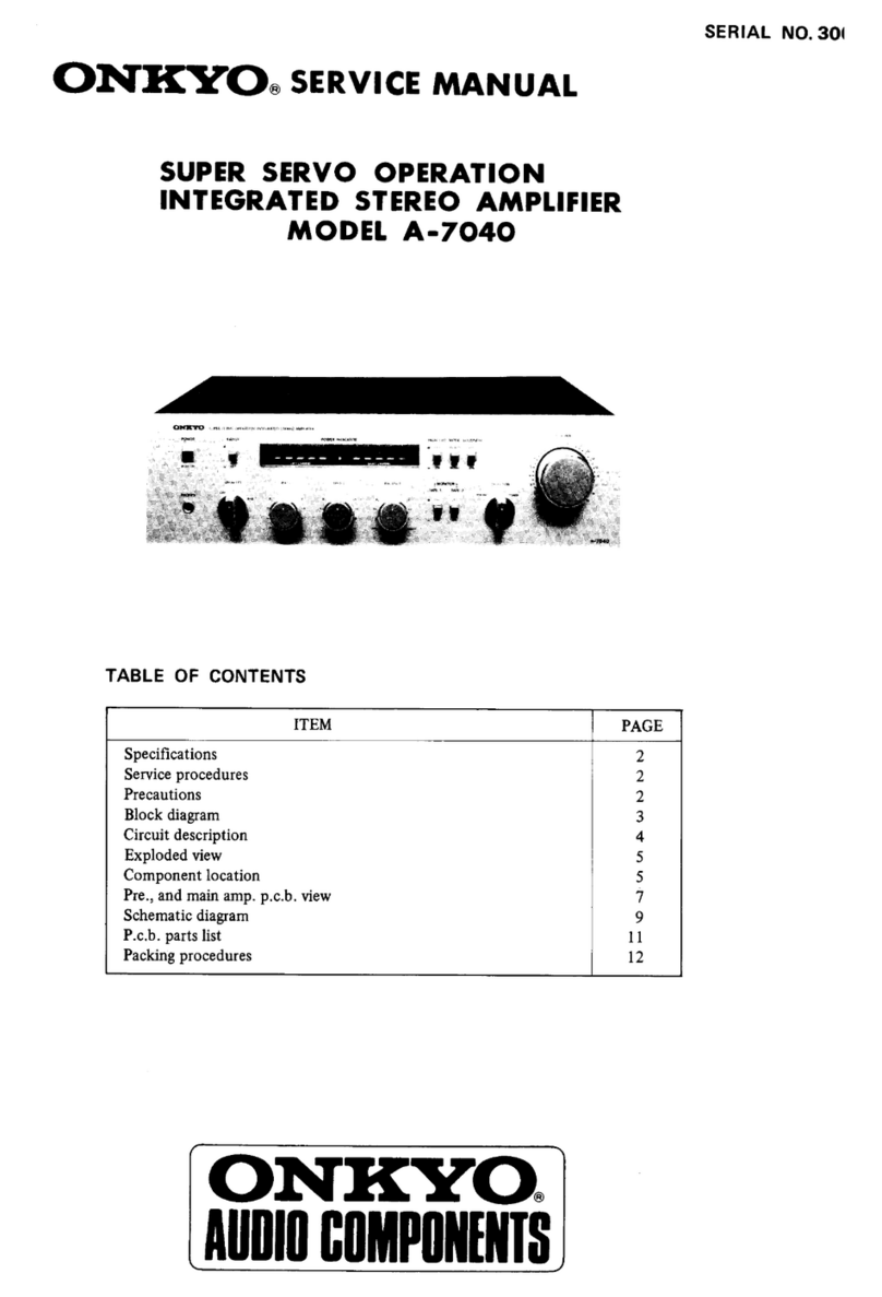
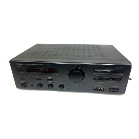
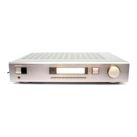
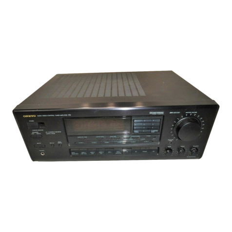
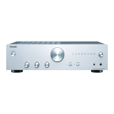
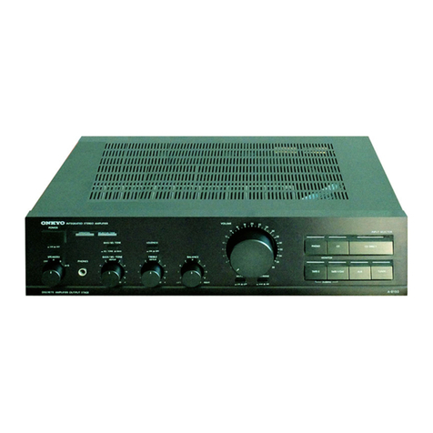
Onkyo A-9210 User manual

na,
ONKY
-00663
A-9210
Integrated
Stereo
Amplifier
Instruction
Manual
ONK
YO
wren
sr
Powe
rene
svuRCE
eee
Pronies
©
eae
(
co
ca
LOUONESS
—TAPE@
MONITC®,
aor
A
sounes
Aa210

Thank
YOU
for
your
purchase
of
the
Onkyo
A-9210
Amplifier.
Please
read
this
manual
thoroughly
before
making
con-
nections
and
turning
power
on.
Following
the
instructions
in
this
manual
will
enable
you
to
obtain
optimum
performance
and
listening
enjoyment
|
from
your
new
A-9210.
Please
retain
this
manual
for
future
reference.
i
Features
Plenty
of
Pristine
Power
With
40
watts
per
channel
into
8
ohms,
20
Hz
to
20
kHz,
0.08%
THD
(dynamic
power:
80
watts/ch
into
4
ohms),
you'll
have
ample
muscle
to
drive
virtually
any
speakers,
and
produce
dynamically
rich
music,
even
at
low
volume
levels.
fi
Discrete
Amplifiers
Rather
than
inexpensive
hybrid
IC
“power
packs”
found
in
some
conventional
amps,
your
A-9210
uses
costly,
discrete
;
amplifiers
to
drive
each
channel.
In
conjunction
with
the
heavy-duty
transformers
and
large
chemical
capacitors,
dis-
crete
outputs
help
the
A-9210
excel
at
accurately
driving
the
most
demanding
low-impedance
loads.
&
Simple,
Direct
Signal
Paths
To
further
reduce
the
possibility
of
noise
or
interference
from
entering
the
signal,
the
signal
paths
are
as
short,
direct
and
sim-
ple
as
possible.
&
ri
Compatible
Remote
Control
Onkyo’s
fQ}
(Remote
Interactive)
remote
control
gives
you
command
of
the
major
functions
of
virtually
any
Onkyo
com-
ponent
that
bears
the
FRY
symbol,
&
Useful
Extras
You'll
Enjoy
®
§
audio
inputs:
To
meet
all
of
your
present
and
future
audio
needs.
@
Heavy-duty,
multiway
speaker
binding
posts:
They
offe:
higher
quality,
more
dependable,
loss-free
speaker
connec-
tion
and
can
easily
accommodate
large
speaker
lugs.
®
Source
direct
switch:
By-passes
treble
&
bass
controls
and
routes
the
music
signal
directly
into
the
power-amp
circuitry,
to
give
you
the
preset
sound
possible
from
any
source.
®
Loudness
control:
Allows
you
to
boost
the
treble
and
bass
frequencies
at
low
volume,
@
Motor-driven
volume
control:
Minimizes
the
possibility
of
signal
degradation
and
gives
you
precise
volume
level
adjustment
by
rernote.
®
Audio
muting:
Allows
you
to
instantly
switch
off
the
sound
(if
you
get
a
phone
cail,
for
example)
or
record
without
lis-
tening.
®
Headphone
jack:
For
private
listening
“WARNING”
“TO
REDUCE
THE
RISK
OF
FIRE
OR
ELECTRIC
SHOCK,
DO
NOT
EXPOSE
THIS
APPLIANCE
TO
RAIN
OR
MOIS-
TURE.”
CAUTION:
“TO
REDUCE
THE
RISK
OF
ELECTRIC
SHOCK,
DO
NOT
REMOVE
COVER
(OR
BACK).
NO
USER-SERVICEABLE
PARTS
INSIDE.
REFER
SERVICING
TO
QUALIFIED
SER-
VICE
PERSONNEL.”
®
This
apparatus
complies
with
requirements
of
EC
directive
87/
308/EEC.
.
®
For
models
having
a
power
cord
with
a
polarized
plug.
CAUTION:
TO
PREVENT
ELECTRIC
SHOCK,
MATCH
WIDE
BLADE
OF
PLUG
TO
WIDE
SLOT,
FULLY
INSERT.
@
Sur
jes
modéles
dont
la
fiche
est
polarisée.
ATTENTION:
pour
EVITER
LES
CHOCS
ELEC-
TRIQUES,
INTRODUIRE
LA
LAME
LA
PLUS
LARGE
DE
LA
FICHE
DANS
LA
BORNE
CORRESPONDANTE
DE
LA
PRISE
ET
POUSSER
JUSQ’
AU
FOND.
@
Replacement
and
mounting
of
an
AC
plug
on
the
power
supply
cord
of
this
unit
should
be
performed
only
by
qualified
service
personnel.
@
IMPORTANT:
The
wires
in
the
mains
lead
are
coloured
in
accordance
with
the
following
code:
Biue:
Neutral
;
Brown:
Live
As
the
colours
of
the
wires
in
the
mains
lead
of
this
apparatus
may
not
correspond
with
the
coloured
markings
identifying
the
termi-
nals
in
your
plag,
proceed
as
follows:
The
wire
which
is
coloured
blue
must
be
connected
to
the
terminal
which
is
marked
with
the
letter
N
or
coloured
black.
The
wire
which
is
coloured
brown
must
be
connected
to
the
termi-
nal
which
is
marked
with
the
letter
L
or
coloured
red.
Supplied
accessories
1
Remote
control
2
Batteries
(size
AA,
R6,
or
UM-3)
1
Remote
control
cable
_
RISK
OF
ELECTRIC.
a
|
DO
NOT
OPEN
@
The
lightning
flash
with
arrowhead
symbol,
within
an
equilateral
triangle,
is
intended
to
alert
the
user
to
the
presence
of
uninsulated
‘“‘danger-
ous
voltage”
within
the
product’s
enclosure
that
may
be
of
sufficient
magnitude
to
constitute
a
|
risk
of
electric
shock
to
persons.
The
exclamation
point
within
an
equilateral
trian-
gle
is
intended
to
alert
the
user
to
the
presence
of
important
operating
and
maintenance
(servicing)
instructions
in
the
literature
accompanying
the
appliance.

Important
safeguards
1.
Read
Instructions
—
All
the
safety
and
operating
instructions
should
be
read
before
the
appliance
is
operated.
2.
Retain
Instructions
—
The
safety
and
operating
instructions
should
be
retained
for
future
reference.
3.
Heed
Warnings
—
All
warnings
on
the
appliance
and
in
the
operat-
ing
instructions
should
be
adhered
to.
4.
Follow
Instructions
—
All
operating
and
use
instructions
should
be
followed.
5.
Water
and
Moisture
-
The
appliance
should
not
be
used
near
water
—
for
example,
near
a
bathtub,
washbowl,
kitchen
sink,
laundry
tub,
in
a
wet
basement,
or
near
a
swimming
pool,
and
the
like.
6.
Carts
and
Stands
—
The
appliance
should
be
used
only
with
a
cart
or
stand
that
is
recommended
by
the
manufacturer.
6A.
An
appliance
and
cart
combination
should
be
moved
with
care.
Quick
stops,
excessive
force,
and
uneven
surfaces
may
cause
the
appliance
and
cart
combination
to
overturn.
PORTABLE
CART
WARNING
$3125A
wr
a
7.
Wall
or
Ceiling
Mounting
—
The
appliance
should
be
mounted
to
a
wall
or
ceiling
only
as
recommended
by
the
manufacturer.
8.
Ventilation
—
The
appliance
should
be
situated
so
that
its
location
or
position
does
not
interfere
with
its
proper
ventilation.
For
example,
the
appliance
should
not
be
situated
on
a
bed,
sofa,
rug,
or
similar
surface
that
may
block
the
ventilation
openings;
or,
placed
in
a
built-in
instal-
lation,
such
as
a
bookcase
or
cabinet
that
may
impede
the
flow
of
air
through
the
ventilation
openings.
9,
Heat
—-
The
appliance
should
be
situated
away
from
heat
sources
such
as
radiators,
heat
registers,
stoves,
or
other
appliances
(including
amplifiers)
that
produce
heat.
10.
Power
Sources
—-
The
appliance
should
be
connected
to
a
power
supply
only
of
the
type
described
in
the
operating
instructions
or
as
marked
on
the
appliance.
1
—
Polarization
—
If
the
appliance
is
provided
with
a
polarized
plug
having
one
blade
wider
than
the
other,
please
read
the
following
infor-
mation:
The
polarization
of
the
plug
is
a
safety
feature.
The
polarized
plug
wiil
only
fit
the
outlet
one
way.
If
the
plug
does
not
fit
fully
into
the
outlet,
try
reversing
it.
If
there
is
still
trouble
inserting
it,
the
user
should
seek
the
services
of
a
qualified
electrician.
Under
no
circum-
stances
should
the
user
attempt
to
defeat
the
polarization
of
the
plug.
1
=
Power-Cord
Protection
—
Power-supply
cords
should
be
routed
so
that
they
are
not
likely
to
be
walked
on
or
pinched
by
items
placed
upon
or
against
them,
especially
near
plugs,
convenience
receptacles,
and
the
point
where
they
exit
from
the
appliance.
13,
ue
Cleaning
-
The
appliance
should
be
cleaned
only
as
recommended
by
the
manufacturer.
14.
Nonuse
Periods
—
The
power
cord
of
the
appliance
should
be
unplugged
from
the
outlet
when
left
unused
for
a
long
period
of
time.
oe
rm
.
Object
and
Liquid
Entry
—
Care
should
be
taken
so
that
objects
do
not
fall
and
liquids
are
not
spilled
into
the
enclosure
through
openings.
1
nN
Damage
Requiring
Service
—
The
appliance
should
be
serviced
by
qualified
service
personnel
when:
.
The
power-supply
cord
or
the
plug
has
been
damaged;
or
.
Objects
have
fallen,
or
liquid
has
been
spilled
into
the
appliance;
or
.
The
appliance
has
been
exposed
to
rain;
or
.
The
appliance
does
not
appear
to
operate
normally
or
exhibits
a
marked
change
in
performance;
or
E.
The
appliance
has
been
dropped,
or
the
enclosure
damaged.
ua
wp
17.
Servicing
-
The
user
should
not
attempt
to
service
the
appliance
beyond
that
described
in
the
operating
instructions.
All
other
servicing
should
be
referred
to
qualified
service
personnel.
Precautions
1.
Warranty
Card
The
serial
number
is
written
on
the
rear
panel
of
this
unit.
Copy
the
serial
number
and
model
number
onto
your
warranty
card
and
keep
it
in
a
safe
place.
2.
Recording
Copyright
Recording
of
copyrighted
material
for
other
than
personal
use
is
illegal
without
permission
of
the
copyright
holder.
3.
AC
Fuse
The
fuse
is
located
inside
the
chassis
and
is
not
user
serviceable.
If
power
does
not
come
on,
contact
your
Onkyo
authorized
service
station.
4.
Care
From
time
to
time
you
should
wipe
the
front
and
rear
panels
and
the
cabinet
with
a
soft
cloth.
For
heavier
dirt,
dampen
a
soft
cloth
in
a
weak
solution
of
mild
detergent
and
water,
wring
it
out
dry,
and
wipe
off the
dirt.
Following
this,
dry
immediately
with
a
clean
cloth.
Do
not
use
rough
material,
thinners,
alcohol
or
other
chemi-
cal
solvents
or
cloths
since
these
could
damage
the
finish
or
remove
the
panel
lettering.
5.
Power
WARNING
BEFORE
PLUGGING
IN
THE
UNIT
FOR
THE
FIRST
TIME,
READ
THE
FOLLOWING
SECTION
CAREFULLY.
e
Some
models
are
designed
for
use
only
with
the
power
supply
voltage
of
the
region
where
they
are
sold.
European
and
Australian
models:
AC
230V,
50Hz
U.S.A.
and
Canadian
models:
AC
120V,
60Hz
Worldwide
model:
AC
120V/220V
switchable,
50/60Hz
e
Voltage
Selector
(Rear
Panel)
Worldwide
models
are
equipped
with
a
voltage
selector
to
con-
form
to
local
power
supplies.
Be
sure
to
set
this
switch
to
match
the
voltage
of
the
power
supply
in
your
area
before
plugging
in
the
unit.
Models
without
a
voltage
selector
can
only
be
used
in
areas
where
the
power
supply
is
the
same
as
that
of
the
unit.
220VU
120V
VOLTAGE
SELECTOR
Setting
the
voltage
selector
1.
Determine
the
proper
voltage
for
your
area:
220V
or
120V.
2.
If
the
preset
voltage
is
not
proper
for
your
area,
insert
a
screwdriver
into
the
groove
in
the
switch.
Slide
the
switch
all
the
way
to
the
right
(120V)
or
to
the
left
(220V),
whichever
is
proper.

For
more
information
about
buttons
or
knobs,
turn
to
page
number
listed
in
the
[
].
Control
positions
and
names
1.
POWER
6.
SOURCE
DIRECT
3.
INPUT
SELECTOR
1.
Power
button
[7]
4.
VOLUME
:
2.
Remote
control
sensor
[6]
3.
Input
Selector
knob
and
indica-
tors
[7,
9,
10]
4.
Volume
control
knob
[7]
5,
Muting
indicator
[8]
6.
Source
Direct
knob
[8]
7.
Source/Tape-2
indicators
[7]
8.
Tape-2
Monitor
button
[7,
10]
9,
Loudness
button
[8]
10.
Balance
control
knob
[8]
i
11.
Treble
control
knob
[8]
13.
SPEAKERS
A,
B
9.
LOUDNESS
12.
Bass
control
knob
[8]
14.
PHONES
8.
TAPE-2
MONITOR
13.
Speaker
selector
buttons
[7]
14,
Headphone
jack
[7]
11.
TREBLE
12.
BASS
10.
BALANCE
—
.
Input
selector
buttons
[7,
9,
10]
2.
Tape
operation
buttons
—a
:
Reverse
play
button
=
:
Forward
play
button
O/1
:
Record/pause
button
NEYO
=
a
:
Stop
button
.
INPUT
wren
«<
:
Fast
rewind
button
SELECTOR
~~}
co
b>
:
Fast
forward
button
3.
CD
operation
buttons
ul
:
Pause
button
.
DECK-A,
;
a
:
Play
button
DECK-B
DISC
_
:
Disc
button
%
ORE
for
CD
changer
6.
MUTING
=
:
Stop
button
.
CD-
ited
:
Down
button
>
ae
ME
PPI
:
Up
button
3
4.
Tuner
operation
buttons
GROUP
:
Group
or
class
selector
button
PRESET
:
Preset
memory
buttons
A(up)/¥
(down)
.
Volume
control
buttons
[7]
NM
.
Audio
muting
button
[8]

Making
system
connections
e
Do
not
plugin
the
power
cord
until
all
connections
have
been
made.
e
Oneach
pair
of
input
jacks,
the
lower
jack
(marked
R)
corresponds
to
the
right
channel,
and
the
upper
jack
(marked
L)
to
the
left
channel.
e
Please
refer
to
the
instruction
manual
of
each
component
when
making
any
connections.
Connect
the
output
leads
of
the
turntable
to
the
PHONO
jacks.
Be
sure
to
connect
the
ground
(earth)
lead
wire
from
the
turntable
to
the
ground
ter-
minal
(GND).
Turntables
not
provided
with
GND
wires
do
not
need
to
be
con-
nected
in
this
way.
Place
the
turntable
on
a
firm
shelf
or
deck
free
from
vibrations
(especially
those
gen-
erated
by
the
speaker
system).
If
the
turnta-
ble
is
permitted
to
pick
up
such
unwanted
vibrations,
not
only
will
the
performance
of
the
unit
drop,
but
distortion
in
the
bass
fre-
quencies
and
howling
in
the
speakers
may
also
occur.
Connect
a
compact
disc
player
to
the
CD
input
jacks.
Connect
an
FM/AM
tuner
to
the
TUNER
input
jacks.
This
unit
is
equipped
with
LINE
input
jacks
for
connection
to
a
wicle
range
of
audio
components
such
as
ari
additional
compact
disc
player,
an
additional
tuner,
a
television
set,
a
VCR,
a
4-channel
stereo
adaptor
and
other
similar
components.

SPEAKER
A
SPEAKER
B
R
ch.
SNPUT
OUTPUT
SPEAKER
A
Lech.
CAUTION:
SPEAKER
IMPEDANCE
Aor
B
:
4
ohms
min./speaker
A+B
:8
ohms
min./speaker
SPEAKER
B
Loch
Pani
This
unit
has
facilities
for
two
tapedecks.
If
you
are
using
only
one
tapedeck,
connect
it
to
the
TAPE-1/DAT
jacks.
If
you
have
two
tapedecks,
connect
one
to
the
TAPE-1/
DAT
jacks
and
the
other
to
the
TAPE-2
jacks.
If
you
wish
to
use
a
graphic
equalizer,
as
well
as
two
tapedecks,
connect
the
graphic
equalizer
to
the
TAPE-2
jacks,
and
connect
the
second
tapedeck
to
the
TAPE
jacks
on
the
graphic
equalizer.
(See
the
figure.)
(@
second
tapedeck,
(6)
graphic
equalizer,
connect
the
OUTPUT
jacks
on
the
graphic
equalizer
to
the
TAPE-2
PLAY
jacks
on
the
A-9210,
and
the
INPUT
jacks
to
the
TAPE-2
REC
jacks
as
shown.)
Please
also
see
page
10
on
how
to
use
a
graphic
equalizer.
Two
separate
pairs
of
speaker
systems
can
be
connected
to
this
unit
at
once.
Please
connect
each
speaker
according
to
the
illustration,
observing
the
correct
con-
nections
for
R,
L,
+
and
-.
e
The
load
impedance
of
each
speaker
system
connected
to
this
unit
must
be
at
least
4
ohms.
(If
using
only
A
or
only
B,
4
ohms
min.;
if
A
and
B,
8
ohms
min.)
e
Do
not
use
unnecessarily
long
or
extremely
thin
speaker
leads.
If
the
DC
resistance
of
the
speaker
leads
is
too
high,
the
damping
factor
will
decrease,
adversely
affecting
the
sound
quality.
e
When
using
only
one
speaker
or
when
you
wish
to
listen
to
monaural
(mono),
the
single
speaker
should
never
be
con-
nected
in
parallel
to
both
the
right
and
left
channel
terminals
at
once.
e@
When
using
banana
plugs,
make
sure
the
speaker
terminal
screws
are
screwed
in
firmly
before
inserting
the
banana
plugs.

Acassette
tape
deck,
compact
disc
player
and
tuner
that
have
the
Onkyo
RI
mark
can
be
operated
using
the
A-9210's
accessory
remote
control.
Please
insert
the
batteries
into
the
remote
control
according
to
the
illustration.
®
Oo
&,
ZS
Remote
control
sensor
approx.
5m
(16
feet)
To
use
the
A-9210
with
an
Onkyo
cas-
sette
tape
deck,
compact
disc
player
and
tuner
with
the
fl
mark,
connect
the
components
together
with
FRI
remote
control
cables,
plugged
into
the
REMOTE
CONTROL
jacks.
.
As
the
exact
connection
sequence
of
the
FRI
cable
is
unimportant,
you
can
con-
nect
from
the
A-9210
to
either
the
tuner,
the
cassette
tape
deck
or
to
the
compact
disc
player.
.
To
operate
correctly,
the
remote
control
must
face
towards
the
remote
control
sensor
of
the
A-9210.
NOTE:
The
left
and
right
I
remote
control
jacks
have
the
same
function.
A
tuner,
cassette
tape
deck,
and
com-
pact
disc
player
that
have
the
Onkyo
fR1
mark
can
be
operated,
using
the
accessory
remote
control
unit.
(FRI:
Remote
Interactive)
Remote
control
operation
is
not
possi-
ble
when
only
the
remote
control
cable
is
connected
—
the
audio
connection
cables
must
also
be
connected.
An
fl
remote
control
cable
equipped
with
a
1/8”
(3.5mm)
diameter
miniature
two-conductor
phone
plug
is
included
with
every
tuner,
compact
disc
player,
or
cassette
tape
deck
with
the
FI
mark.
Average
battery
life
is
about
one
year,
depending
upon
the
frequency
of
use
and
the
environment
(temperature
and
humid-
ity)
in
which
the
remote
control
is
used.
Only
use
batteries
of
the
kind
specified
in
the
table
below.
Vounge
|
Size
_|
AA,
R6
ve
eee
Warning
Do
not
leave
an
expired
battery
in
the
case
—
it
may
leak
or
damage
the
remote
control.
Do
not
use
nickel
cadmium
(recharge-
able)
batteries.
Replace
both
batteries
at
once;
do
not
use
one
old
battery
and
one
new
battery.
The
following
information
will
help
you
get
optimal
use
from
the
remote
control.
-
Place
the
A-9210
away
from
direct
bright
light,
which
can
prevent
proper
operation
of
the
remote
control.
Make
sure
audio
rack
doors
do
not
have
colored
glass.
If
the
A-9210
is
placed
behind
such
a
door,
this
may
prevent
proper
remote
control
operation.
Using
other
remote
controls
in
the
same
room
as
the
A-9210
remote
control
may
cause
interference.

Operations
2.
POWER
1.
INPUT
SELECTOR
4.
VOLUME
i
TAPE-2
indicator
INPUT
SELECTOR
INPUT
SELECTOR
TAPE-2
TAPE-1
TUNER
co
(2):
(ES
SESE
LINE
A
SPEAKERS
B
VOLUME
TAPE-2
MONITOR
button
TAPE-2
MONITOR
RB
SOURCE
m™
TAPE-2
When
operating
the
unit
connected
to
tape-2,
the
TAPE-2
MONITOR
button
must
be
turned
on
for
TAPE-2
position.
The
TAPE-2°
indicator
illuminates,
indicating
the
monitoring
§
state.
|
77
SOURCE
indicator
Before
plugging
in
the
unit,
confirm
that
all
connections
have
been
made
properly.
1.
Insert
the
AC
power
supply
cord
into
the
wall
outlet.
Press
the
POWER
button.
2.
e
Select
your
favorite
source
using
the
input
selector
(e.g.
PHONO).
If
you
turn
the
INPUT
SELECTOR
knob
to
the
right,
the
indicators
will
light
up
one
at
a
time
in
a
clockwise
direction.
Turning
the
knob
to
the
left
will
reverse
the
direction.
Select
the
speakers.
Select
and
press
the
button
for
the
speakers
that
you
want
to
listen
to
(SPEAKERS
A
and/or
SPEAKERS
B).
From
now
on
you
will
be
able
to
hear
from
the
speakers
any
sound
going
through
the
A-9210.
If
both
SPEAK-
ERS
A
and
B
buttons
are
set
to
OFF,
no
sound
will
come
from
the
speakers.
.
Start
the
selected
input
source
playing.
Follow
the
operating
instructions
for
that
unit.
.
Adjust
the
level.
Turn
the
VOLUME
knob
clockwise
or
press
the
A(up)
button
on
the
remote
control
to
increase
the
volume
level.
Turn
counterclockwise
or
press
the
V(down)
button
on
the
remote
control
to
decrease
the
volume
level.
Confirm
the
SOURCE
indicator
illumi-
nate.
If
the
indicator
does
not
illumi-
nate,
press
the
TAPE-2
MONITOR
button
for
SOURCE
position.
NN
Stereo
headphones
with
a
standard
binaural
(stereo)
plug
can
be
connected
here.
When
the
headphone
plug
is
inserted,
the
speakers
are
not
automatically
muted
but
can
be
controlled
with
the
SPEAKERS
A/
B
buttons.

Adjusting
the
tone
SOURCE
DIRECT
Muting
indicator
YOLUME
MUTING
SOURCE
DIRECT
DIRECT
TONE
BAS:
TREBLE
DEFEAT
LOUDNESS
it
OFF
=
ON
SOURCE
DIRECT
DIRECT
TONE
TREBLE
LODUDNESS
Press
the
MUTING
button
on
the
remote
control.
This
button
temporarily
switches
off
the
sound
from
the
speakers
or
headphones.
The
MUTING
indicator
blinks.
To
cancel,
e
press
the
MUTING
button
again,
or
e
adjust
the
volume
with
the
remote
control,
or
e
turn
the
power
off,
then
on.
Turn
the
SOURCE
DIRECT
knob
to
the
TONE
position
and
adjust
to
your
desired
tone.
BASS
_
:Tum
this
knob
clockwise
to
boost
or
counterclockwise
to
attenuate
the
bass.
When
this
knob
is
in
the
center
position,
the
frequency
response
of
the
bass
tone
control
is
flat,
i.e.
the
bass
is
neither
boosted
nor
attenuated.
TREBLE
:
Turn
this
knob
clockwise
to
boost
or
counterclockwise
to
attenuate
the
treble.
When
this
knob
is
in
the
center
posi-
tion,
the
frequency
response
of
treble
tone
control
is
flat,
i.e.
the
treble
is
neither
boosted
nor
attenuated.
When
turned
to
the
extreme
left,
the
treble
control
acts
as
a
high
cut
filter
to
eliminate
scratches,
hissing
and
other
high
frequency
noise.
NOTE:
When
the
SOURCE
DIRECT
knob
is
set
to
DIRECT,
the
bass
and
tre-
ble
can
not
be
adjusted.
:
By
pressing
the
LOUDNESS
button,
both
treble
and
bass
are.
rein-
forced
even
when
the
volume
is
turned
down
low.
Use
this
button
according
to
the
music
source
and
according
to
the
listening
area.
Its
purpose
is
to
enrich
the
natural
sound
effects
of
both
the
treble
and
bass.
The
BALANCE
knob
is
used
to
control
the
relative
volume
level
of
the
left
and
right
speaker
systems
or
headphones.
By
selecting
DIRECT,
you
can
obtain
the
purest
possible
sound
repro-
duction,
by
bypassing
the
bass
and
treble
controls.
It
is
still
possible
to
adjust
the
volume.

Recording
INPUT
SELECTOR
INPUT
SELECTOR
TAPE-2.
TAPE-t
TUNER
TAPE-1/DAT
PLAY
co
=
mene
oo
sez
lel:
SS
INPUT
SELECTOR
INPUT
SELECTOR
*TAPE-2.
TAPE-1
TUNER
cD
LINE
ae).
Ee]
When
recording
the
same
source
being
lis-
tened
to
(e.g.
when
recording
on
TAPE-1/
DAT
and/or
TAPE-2
from
a
CD):
1.
Select
CD
with
the
input
selector.
If
you
turn
the
INPUT
SELECTOR
knob
clockwise,
the
indicators
will
light
up
one
at
a
time
in
a
clockwise
direc-
tion.
Turning
the
knob
counterclock-
wise
will
reverse
the
direction.
2.
Insert
the
CD
that
you
want
to
record
into
the
CD
player.
Insert
into
the
tapedeck(s)
connected
to
TAPE-1/
DAT
and/or
TAPE-2
a
blank
tape
to
record
onto.
3.
Press
the
record
button
on
the
tape-
deck,
then
the
play
button
on
the
CD
player.
e@
When
TAPE-1/DAT
is
selected
with
the
INPUT
SELECTOR,
it
will
record
to
the
TAPE-2
REC
jacks.
e@
You
are
able
to
record
the
source
selected
with
the
INPUT
SELECTOR
onto
TAPE-2
whether
the
TAPE-2
MONITOR
button
is
turned
on
or
off.
e
When
either
PHONO,
TUNER,
CD
or
LINE
is
selected,
you
are
able
to
record
to
both
the
TAPE-1/DAT
and
TAPE-2
REC
jacks.
NOTE:
Do
not
change
the
INPUT
SELECTOR
while
recording
Using
two
tapedecks
to
copy
one
tape
to
.
another
tape
is
called
tape
dubbing.
Select
the
TAPE-1/DAT
on
the
INPUT
SELECTOR.
e
If
a
3-headed
deck
is
used
and
the
TAPE-2
MONITOR
button
is
turned
on,
you
will
be
able
to
listen
to
(moni-
tor)
the
sound
being
recorded.
NOTE:
e
You
are
only
able
to
dub
from
TAPE-1
to
TAPE-2.
e
Do
not
change
the
INPUT
SELECTOR
while
dubbing.

Connecting
a
graphic
equalizer
INPUT
SELECTOR
TAPE-2
indicator
TAPE-2
MONITOR
EQUALIZER
TAPE-2
MONITOR
SOURCE
um
TAPE-2
INPUT
SELECTOR
INPUT
SELECTOR
TAPE-2
TAPE-+
TUNER
co
When
connecting
the
A-9210
to
a
graphic
equalizer,
connect
the
graphic
equalizer’s
input
jacks
to
the
A-9210’s
TAPE-2
REC
jacks.
Also,
connect
the
graphic
equalizer’s
output
terminals
to
the
A-9210’s
TAPE-2
PLAY
jacks.
1.
Press
the
TAPE-2
MONITOR
button
to
the
TAPE-2
position,
and
TAPE-2
indicator
will
illuminate.
Select
CD,
TUNER,
LINE,
TAPE-1/
DAT
or
PHONO
(whichever
one
you
want
to
listen
to)
on
the
INPUT
SELECTOR.
Operate
the
graphic
equalizer.
.
Begin
playing.
Depending
on
the
particular
graphic
equalizer
used,
it
may
provide
features
such
as
muting
and
balance,
as
well
as
tone
control
(equalization).
For
the
equalization
of
a
source
other
than
a
CD,
tuner,
or
phono,
connect
the
source
device
to
the
amplifier’s
CD,
TUNER,
or
LINE
input
jacks.
(If
the
device
is
connected
to
a
jack
other
than
the
CD,
TUNER,
LINE
or
PHONO
input
jacks,
equalization
is
not
possi-
ble.)
10

Troubleshooting
guide
e
No
power.
Cause:
The
power
cord
is
not
plugged
in.
Remedy:
Plug
in
the
power
cord.
Cause:
AC
fuse
blown.
Remedy:
Contact
Onkyo
Service
Center.
e
Power
but
no
sound.
Cause:
Bad
connections.
Remedy:
Check
input
leads,
pin
plugs,
etc.
e
Hum,
low
frequency
noise.
Cause:
Poor
or
no
input
ground.
Remedy:
Check
outer
conductor
of
input
plugs.
Cause:
Poor
or
no
phono
motor
ground.
Remedy:
Check
for
proper
ground
connection.
e
Howling
when
the
volume
is
turned
up.
Cause:
Turntable
and
speakers
are
too
close
together.
Remedy:
Move
them
farther
apart.
e
Rough
or
scratchy
sound.
High
range
is
not
clear.
Cause:
Stylus
of
pick-up
is
worn.
Remedy:
Replace.
Cause:
Stylus
is
dirty.
Remedy:
Clean.
Cause:
Treble
control
is
too
high.
Remedy:
Turn
treble
control
down.
e
Front
panel
controls
function
but
remote
control
does
not.
Cause:
No
batteries
in
remote
control.
Remedy:
Insert
batteries.
Cause:
Batteries
have
worn
out.
Remedy:
Replace
batteries.
Specifications
Power
output:
40
watts
per
channel,
min
RMS,
at
8
ohms,
both
channels
driven
from
20
Hz
to
20
kHz,
with
no
more
than
0.08%
THD.
2
x
60
watts
at
4
ohms,
1
kHz
(DIN)
2
x
50
watts
at
8
ohms,
1
kHz
(DIN)
Total
Harmonic
Distortion:
0.08%
at
rated
power
IM
Distortion:
0.08%
at
rated
power
Damping
Factor:
150
at
8
ohms
Frequency
response:
15
Hz—S50
kHz
+1
dB
Input
sensitivityimpedance
Phono:
2.5
mV/S50
kohms
Tuner/CD/Line:
150
mV/25
kohms
Tape
Play:
150
mV/25 kohms
Output
sensitivityimpedance
Tape
Rec:
150
mV/3
kohms
(phono)
Phono
overload:
135
mV
RMS
at
1
kHz,
0.1%
THD
(REC)
Bass
control:
+8
dB
at
100
Hz
Treble
control:
+8
dB
at
10
kHz
Loudness
control:
+8
dB
at
100
Hz
+3
dB
at
10
kHz
Signal
to
noise
ratio
THF-A)
Phono:
84
dB
(5
mV
input)
Source
Direct:
104
dB
(0.5
V
input)
(CD)
General
Power
supply:
European
and
Australian
models:
AC
230
V,
50
Hz
Worldwide
models:
AC
120
V
and
220
V
switchable,
50
Hz/60
Hz
Dimensions:
455
(W)
x
120
(H)
x
332
(D)
mm
17-15/16”
x
4-3/4”
x
13-1/16”
Weight:
7.1
kg,
15.7
Ibs.
Remote
control
RC-286S
Transmitter:
Infrared
Signal
range:
Approx.
5
meters,
16ft
Power
supply:
Two
“AA”
batteries
(1.5
V
x
2)
Dimensions:
55
(W)
x
18
(H)
x
194
(D)
mm
2-3/16”
x
11/16”
x
7-5/8”
Weight:
100
grams.
3.5
oz.
(including
batteries)
Specifications
and
features
are
subject
to
change
without
notice.
ONKYO
CORPORATION
Sales
Planning
&
Promotion
Dept.
:
2-1,
Nisshin-cho,
Neyagawa-shi,
OSAKA
572,
JAPAN
Tel:
0720-31-8111
Fax:
0720-33-5222
ONKYO
U.S.A
CORPORATION
200
Williams
Drive,
Ramsey,
N.J.
07446,
U.S.A.
Tel:
201-825-7950
Fax:
201-825-8150
ONKYO
DEUTSCHLAND
GMBH
ELECTRONICS
industriestrasse
18-20,
82110
Germering,
GERMANY
Tel:
089
84
93
20
Fax:
089
84 93
226
ONKYO
FRANCE
Immeuble
Le
Diamant,
Domaine
Technologique
de
Saclay,
4
Rue
René
Razel,
91892
SACLAY,
FRANCE
Tel:
(1)
69
33
14
00
Fax:
(1)
69
41
35 84
SN
29342083Y
107960
Table of contents
Other Onkyo Amplifier manuals

Onkyo
Onkyo TX-8210 User manual

Onkyo
Onkyo TX-903 User manual

Onkyo
Onkyo TX-SV515PRO II User manual
Onkyo
Onkyo A-8870 User manual

Onkyo
Onkyo A-8150 User manual

Onkyo
Onkyo A-RV410 User manual

Onkyo
Onkyo A-8015 User manual

Onkyo
Onkyo A-905TX User manual

Onkyo
Onkyo TX-SV727 User manual

Onkyo
Onkyo PA-MC5500 User manual