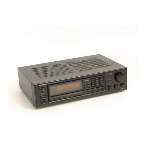
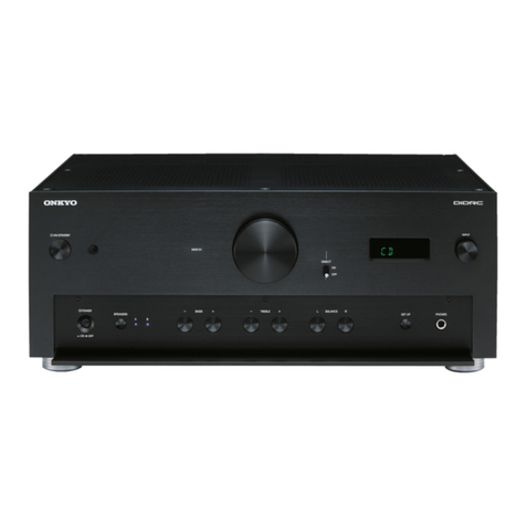
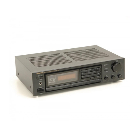
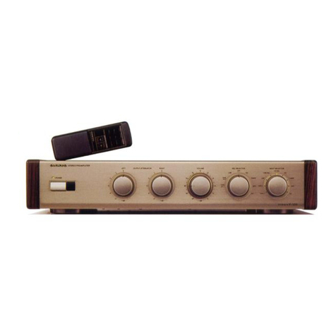
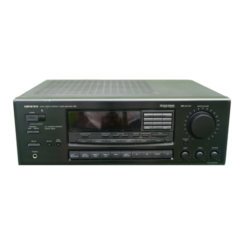
Onkyo TX-108 User manual

Artistry
in
Sound
ONKYO.
TX-108/88
Computer
Controlled
Tuner
Amplifier

e
Thank
you
for
purchasing
the
ONKYO
INTEGRA
TX-708/88
Tuner-Amplifier.
e
Please
read
this
manual
thoroughly
before
connecting
up
your
new
tuner-amplifier,
and
turning
it
on.
@
Following
the
instructions
in
this
manual
will
enable
you
to
obtain
the
utmost
listening
enjoyment
from
your
new
TX-108/88.
©
Please
keep
the
manual
for
later
reference.
CONTENTS
FEATURES
.0....ecccccccccseccesceseeneeeseeenseeeaeeesseseceetenerissesissntansasstessissisessinsseisissussitassissesensestussnsicensestisnteerseenseseneeeen
1
IMPORTANT
SAFEGUARDS
uo.
ce
cre
ee
nee
ntenttsissetiesssesseassiensanseissesnsseeserseieesansnieneaee
tite
2
PRECAUTIONS
o.o.occcccccceccee
cscs
eeseee
ees
eesee
ces
neneeneaneneenesesseesciisrseisantensisiitiesissisinssseisensessneitensnseseereeeiseeeineeen
2
SYSTEM
CONNECTIONS
0000.
ne
eens
renenentnsieenrneissitietisnitiessenseereensieresaeisessisesneacens
3
FRONT
PANEL
FACILITIES
0.0.0.0
crescent
csntresesitansissitieriesissnsseeceaisesssseeisemnseisneeeeieneaeeen
6
OPERATIONS
ooo.
cece
eens
nse
centeneereacsnesesistissesnsansseeassasensserssesiasssicesisssissesisissessaesseesseansseeseensees
10
TROUBLESHOOTING
GUIDE
oo.
eis
eee
rre
cetera
reersiesesietesesniaseeisenseeisenssesensieesenseneenen
14
SPECIFICATIONS
0.0...
terrence
eesti
ntecatsntesinisenteitaesssnesesuseissersenssernsersaisensissnenerseneensees
15
FEA
TURES
The
Integra
Series
brings
together
all
of
ONKYO’s
innovative
technology
and
experience
to
deliver
audio
excellence,
the
Integra
Series
TX-108/88
Tuner
Amplifiers
combine
the
best
features
of
stand-alone
tuners
and
amplifiers
to
produce
the
ultimate
in
livelike
sound
re-
production.
The
TX-108/88
features:
@
Microcomputer
controlled
functions
*
A
logic
circuitry
controls
the
APR
(Automatic
Precision
Reception)
system,
to
obtain
the
best
possible
sound
quality
from
FM
broadcasts.
ONKYO’s
exclusive
APR
system
automatically
selects
the
optimum
combination
of
RF
sensitivity,
Hi-blend,
mode
and
noise
reduction
for
superb
reception.
*
The
same
processor
also
controls
the
random
access,
random
program
16
station
memory,
and
the
tuning
and
input
selectors,
for
true
ease
of
use.
@
Control
center
of
your
audio
visual
system
The
Real
Phase
Amp
offers
a
complete
range
of
user-selectable
functions
to
make
the
TX-108/88
the
central
controlting
unit
of
a
complete
home
entertainment
system.
*
Sound
Processor:
Simulated
Stereo
Imager
(SSI),
to
broaden
the
stereo
effect
and
sense
of
space.
Dynamic
Bass
Expander
(DBE),
to
dynamically
boost
the
bass
according
to
the
input
signal
level.
Dynamic
Transient
Expander
(DTE),
to
enhance
the
gain
for
more
dramatic
sound
(TX-108).
*
Multiple
Inputs:
Seven
input
terminals
for
full
source
versatility,
including
direct
connection
for
CD
player,
two
video
cassette
recorders
or
video
disk
player
to
VCR
(direct
A/V
dubbing
capability),
two
tape
recorders,
tuner
and
turntable.
*
Remote
Control:
The
remote
control
allows
precise
adjustment
of
the
volume
level
from
the
listening
position.
An
LED
in
the
contro]
knob
gives
a
visual
indication
of
the
volume
setting,
even
from
the
other
side
of
the
room.
The
remote
control
is
capable
of
selecting
any
connected
equipment,
inciuding
all
inputs,
all
pre-set
stations,
CD
player
controls,
tape
controls,
and
muting
and
power
switches.
The
ultimate
in
user-convenience.
@®
High
Power
Output
with
Real
Phase
The
TX-108
and
TX-88
deliver
plenty
of
clean
power
even
into
low
impedance
loads,
and
have
lots
to
spare
for
effortless
handling
of
instantaneous
signal
peaks,
making
the
amplifier
sections
truly
the
equal
of
even
much
more
expensive
integrated
amps.
Both
also
Feature
Onkyo’s
exclusive
Real
Phase
for
clear,
accurate
stereo
imaging
and
extra
definition.
A
special
“In-Phase”
transformer
(in
addition
to
the
power
transformer)
“flattens
out”
the
charging
currents
in
the
power
supply.
Since
the
currents
are
no
longer
modulated
by
very
low
frequency
input
out-of-phase
signals
that
could
muddy
the
sound.
As
an
added
convenience,
the
back
panel
is
equipped
with
heavy-duty
speaker
terminals,
specially
designed
to
accomodate
both
single
and
parallel
banana
piugs
(TX-108).
“WARNING”
"TO
REDUCE
THE
RISK
OF
FIRE
OR
ELECTRIC
SHOCK,
DO
NOT
EXPOSE
THIS
APPLIANCE
TO
RAIN
OR
MOISTURE.
@
The
lightning
flash
with
arrowhead
symbol,
within
an
equilateral
triangle,
is
intended
to
alert
CAUTION
the
user
to
the
presence
of
uninsulated
“dan-
“TO
REDUCE
THE
RISK
OF
ELECTRIC
SHOCK,
DO
NOT
gerous
voltage”
within
the
product's
enclosure
REMOVE
COVER
(OR
BACK),
NO
USER-SERVICEABLE
that
may
be
af
sufficient
magnitude
to
constitute
PARTS
INSIDE.
REFER
SERVICING
TO
QUALIFIED
SERVICE
a
risk
of
electric
shock
to
persons.
The
exclamation
point
within
an
equilateral
PERSONNEL.”
eT
'
triangle
is
intended
to
alert
the
user
to
the
CAU
T
ION
presence
of
important operating
and
mainte-
nance
(servicing)
instructions
in
the
literature
RISK
OF
ELECTRIC
SHOCK
accompanying
the
appliance.
DO
NOT
OPEN

®
For
models
having
power
cords
with
a
polarized
plug.
CAUTION:
to
prevent
ELECTRIC
SHOCK.
DO
NOT
USE
THIS
(POLARIZED)
PLUG
WITH
AN
EXTENSION
CORD,
RECEPTACLE
OR
OTHER
OUTLET
UNLESS
THE
BLADES
CAN
BE
FULLY
INSERTED
TO
PREVENT
BLADE
EXPOSURE.
@
Sur
les
modéles
dont
la
fiche
est
polarisée.
ATTENTION:
POUR
PREVENIR
LES
CHOCS
ELECTRIQUES
NE
PAS
UTILISER
CETTE
FICHE
POLARISEE
AVEC
UN
PROLONGATEUR.
UNE
PRISE
DE
COURANT
OU
UNE
AUTRE
SORTIE
DE
COURANT,
SAUF
SI
LES
LAMES
PEUVENT
ETRE
INSEREES
A
FOND
SANS
EN
LAISSER
AUCUNE
PARTIE
A
DECOUVERT.
IMPORTANT
SAFEGUARDS
1.
Read
Instructions
—
All
the
safety
and
operating
instructions
should
be
read
before
the
appliance
ts
operated.
i)
Retain
Instructions
—
The
safety
and
operating
instructions
should
be
retained
for
future
reference.
3.
Heed
Warnings
—
All
warnings
on
the
appliance
and
in
the
operating
instructions
should
be
adhered
ta.
4.
Follow
Instructions
—
Aj!
operating
and
use
instructions
should
be
followed.
5.
Water
and
Moisture
—
The
appliance
shouid
not
be
used
near
water
-
for
example,
near
a
bathtub,
washbow},
kitchen
sink.
laundry
tub,
in
a
Wet
basement,
or
near
a
swimming
pool,
and
the
like.
6.
Carts
and
Stands
—
The
appliance
should
be
used
only
with
a
cart
or
stand
that
Is
recommended
by
the
manufacturer.
7.
Wall
or
Ceiling
Mounting
-
The
appliance
should
be
mounted
to
a
wall
or
ceiling
only
as
recommended
by
the
manufacturer.
8.
Ventilation
—
The
appliance
should
be
situated
so
that
its
location
or
position
does
not
interfere
with
its
proper
ventilation.
For
example,
the
appliance
should
not
be
situated
on
a
bed.
sofa,
rug,
or
similar
surface
that
may
block
the
ventilation
openings:
or,
placed
in
a
built-in
installation,
such
as
a
bookcase
or
cabinet
that
may
impede
the
flow
of
air
through
the
ventilation
openings.
9.
Heat
—
The
appliance
should
be
situated
away
from
heat
sources
such
as
radiators,
heat
registers,
stoves,
or
other
appliances
(tnciuding
amplifiers)
that
produce
heat.
10.
Power
Sources
—
The
appliance
should
be
connected
to
a
power
supply
only
of
the
type
described
in
the
operating
instructians
or
as
marked
on
the
appliance.
11.
Grounding
or
Polarization
—
The
precautions
that
should
be
taken
so
that
the
grounding
or
polarization
means
of
an
appliance
is
not
defeated.
12.
Power-Cord
Protection
-
Power-supply
cords
should
be
routed
so
that
they
are
not
lkely
to
be
walked
on
or
pinched
by
ttems
placed
upan
or
against
them,
paying
particular
attention
to
cords
at
plugs,
convenience
receptacles,
and
the
point
where
they
exit
from
the
ap-
phance.
13.
Cleaning
-
The
appliance
should
be
cleaned
only
as
recommended
by
the
manufacturer.
14.
Power
Lines
power
lines.
An
outdooor
antenna
should
be
located
away
fram
15.
Outdoor
Antenna
Grounding
—
If
an
outside
antenna
is
connected
to
the
receiver,
be
sure
the
antenna
system
is
grounded
so
as
to
provide
some
protection
against
voltage
surges
and
built
up
static
charges.
Section
810
of
the
Nationa!
Electrical
Code,
ANSI/NFPA
No.
70-1984,
provides
information
with
respect
to
proper
grounding
of
the
mast
and
supporting
Structure,
grounding
of
the
lead-in
wire
to
an
antenna
discharge
unit,
size
of
grounding
conductors,
location
of
the
anten-
na-discharge
unit,
connection
to
grounding
electrodes,
and
require-
ments
for
the
grounding
electrode.
See
Figure
65.1.
FIGURE
65.1:
EXAMPLE
OF
ANTENNA
GROUNDING
ACCORDING
TO
NATIONAL
ELECTRICAL
CODE
INSTRUCTIONS
CON-
TAINED
IN
ARTICLE
810
—-
“RADIO
AND
TELEVISION
EQUIPMENT”
ho
GROUND
SERVICE
ENTRANCE
camp
CONDUCTORS
STANDOFF
|
INSULATORSD
5
Tt
|
MAST
hae
b+
ANTENNA
f
}
LEAD-IN
WIRE
SERVICE
=
ENTRANCE
y\|
ANTENNA-
EQUIPMENT
DISCHARGE
"4,
UNITS
TO
EXTERNAL
ANTENNA
|
TERMINALS
OF
.
PRODUCT
GROUND
WIRE@-b
GROUND
CLAMPS
OPTIONAL
ANTENNA-GROUNDING
ELECTRODE.
DRIVEN
8
FEET
(2
44m)
INTO
THE
EARTH
IF
REQUIRED
BY
LOCAL
CODES.
SEE
NEC
SECTION
810-21
(f).
POWER
SERVICE
GROUNDING
ELECTRODE
SYSTEM
(e.g.
interior
metal
water
pipe)
|
BONDING
JUMPER®
$2898
4
Use
No.
10
AWG
(5.3
mm?)
copper,
No.
8
AWG
(8.4
mm?)
aluminum,
No.
17
AWG
(1.0
mm?)
copper-clad
steel
or
bronze
wire,
or
larger,
as
a
ground
wire.
b
Secure
antenna
lead-in
and
ground
wires
to
house
with
stand-off
tnsu-
lators
spaced
from
4—6
feet
(1.22—1.82
m)
apart.
©
Mount
antenna
discharge
unit
as
close
as
possible
to
where
lead-in
enters
house.
d
Use
jumper
wire
not
smaller
than
No.
6
AWG
(13.3
mm)
copper,
or
the
equivalent,
when
a
separate
antenna-grounding
electrode
is
used.
See
NEC
Section
810-21
(j).
Figure
65.1
revised
August
24,
1984
16.
Nonuse
Periods
—
The
power
cord
of
the
appliance
should
be
un-
plugged
from
the
outlet
when
left
unused
for
a
tong
period
of
time.
17.
Object
and
Liquid
Entry
—
Care
should
be
taken
so
that
objects
cdo
not
fall
and
liquids
are
not
spilled
into
the
enclosure
through
openings.
18.
Damage
Requiring
Service
—
The
appliance
should
be
serviced
by
qualified
service
personnel
when:
A.
The
power-supply
cord
or
the
plug
has
been
damaged:
or
B.
Objects
have
fallen,
or
liquid
has
been
spiiled
into
the
appliance;
or
C.
The
appliance
has
been
exposed
to
rain;
or
D..
The
appliance
does
not
appear
to
operate
normally
or
exhibits
a
marked
change
in
performance;
or
E.
The
appliance
has
been
dropped
or
the
enclosure
damaged.
19.
Servicing
-—
The
user
should
not
attempt
to
service
the
appliance
beyond
that
described
tn
the
operating
tnstructions.
Ail
other
servicing
should
be
referred
to
qualified
service
personnel.
PRECAUTION
1.
Warranty
Card
The
serial
number
is
written
on
the
rear
panel
of
this
unit.
Copy
the
serial
number
and
mode!
number
onto
your
warrnty
card
and
keep
it
in
a
safe
place.
2.
Cabinet
Materials
The
Side
Pannei
of
this
unit
is
vinyl
overlay
particle
board;
TX-108
only.
3.
Recording
Copyright
Recording
of
copyrighted
material
for
other
than
per-
sonal
use
its
illegal
without
permission
of
the
copyright
holder.
4.
Power
WARNING
BEFORE
TURNING
ON
POWER
FOR
THE
FIRST
TIME,
READ
THE
FOLLOWING
SECTION
CAREFULLY.
@®
Some
models
are
designed
for
use
only
with
the
power
supply
voltage
of
the
region
where
they
are
sold.
USA
&
Canadian
models:
AC120V,
60Hz
Worldwide
models:
AC
120V,
60Hz/
220V,
50Hz
switchable,

@
Voltage
Selector
(Rear
Panel)
Worldwide
models
are
equipped
with
a
voltage
selector
to
conform
with
local
power
supplies.
Be
sure
to
set
this
switch
to
match
the
voltage
of
the
power
supply
in
your
area
before
turning
the
power
switch
on.
Voltage
is
changed
by
sliding
the
groove
in
the
switch
with
a
screwdriver
to
the
right
or
left.
Confirm
that
the
switch
has
been
moved
ail
the
way
to
the
right
or
left
before
turning
the
power
switch
on.
Models
without
a
voltage
selector
can
only
be
used
in
areas
where
the
power
supply
is
the
same
as
that
of
the
unit.
220V
~
120V
~
atAC220V
220V
~
120V
~
atAC120V
5.
AC
Fuse
The
fuses
are
located
inside
the
chassis
and
are
not
user
serviceable.
If
power
does
not
come
on,
contact
your
Onkyo
dealer.
6.
Remote
Controlier
@
|if
you
have
any
questions
concerning
remote
control
operation
of
an
Onkyo
CD
player,
cassette
deck
or
turntable
connected
to
the
TX-108/88,
contact
your
Onkyo
dealer.
®
Batteries
The
remote
controtler
is
powered
by
two
batteries.
Before
using
this
unit
for
the
first
time,
insert
the
two
batteries
(included)
as
shown
in
the
diagram.
The
remote
controller
has
no
on/off
switch.
Average
battery
life
is
one
year.
This
period
may
be
shorter
depending
on
the
frequency
of
use
and
environment
(temperature
and
humidity)
in
which
the
remote
controller
ts
used.
If
the
remote
controller
does
not
or?rate
even
though
front
panel
controls
function
normally,
the
batteries
should
be
replaced.
Use
only
batteries
listed
in
the
following
chart.
AA
Mange
1.5V
R6
ese
UM-3
Note
1.
The
battery
life
is
influenced
by
the
way
they
are
used,
temperature,
humidity
and
many
other
factors.
On
the
average,
they
should
last
for
about
one
year.
2.
Do
not
leave
an
expired
battery
in
the
case
as
it
may
leak
or
damage
the
battery
case.
3.
When
inserting
the
batteries,
be
sure
the
(+)
and
(—)
ends
are
properly
aligned.
4.
Do
not
use
nickel-cadmium
(rechargeable)
batteries.
©
5.
Do
not
use
one
specified
(manganese)
battery
and
one
alkaline
battery
at
the
same
time.
6.
Replace
both
batteries
at
once;
do
not
use
one
old
and
one
new
battery
together.
@
De-Emphasis
and
Tuning
Step
Frequency
Switch
(Bottom)
Some
models
are
equipped
with
a
switch
that
controls
both
de-emphasis
(50
usec
—
75
psec)
and
the
AM
(9kHz/10kHz)
and
FM
(50kHz/200kHz)
band
tuning
steps.
Be
sure
to
set
this
switch
to
match
the
De-Emphasis
and
tuning
step
frequency
in
your
area.
U.S.A
7
5usec
10kHz/200kz
Other
areas
50yusec
9kHz/50kHz
e
“Note
to
CATV
system
installer:
This
reminder
is
provided
to
call
the
CATV
system
installer’s
attention
to
Article
820-22
of
the
NEC
that
provides
guidelines
for
proper
grounding
and,
in
particular,
specifies
that
the
cable
ground
shall
be
connected
to
the
grounding
system
of
the
building,
as
close
to
the
point
of
cable
entry
as
practical.”
SYSTEM
CONNECTIONS
NOTE:
Remote
control
operation
of
a
cassette
deck
(or
turnt-
able)
is
not
possible
when
only
the
remote
contro!
DIN
cable
is
connected.
The
in
and
out
pin
cables
for
the
signal
must
also
be
connected
before
remote
control
operation
functions.
Be
sure
that
both
cables
are
firmly
inserted
before
using
the
cassette
deck
(or
turntable)
remote
control
function.
The DIN
cord
(for
cassette
deck
and
turntable)
can
be
found
in
the
bag
containing
the
instruction
manual.
General
Switch
the
main
power
switch
off
before
performing
connections.
Also
be
sure
to
perform
left
and
right
channel
connections
properly.
AC
Outlets
UNSWITCHED:
Power
is
supplied
to
this
outlet
regard-
less
of
the
position
of
the
front
panel
system
and
main
power
switches.
Capacity
is
100
watts.
SWITCHED:
These
two
outlets
are
switched
on
and
off
together
with
the
front
panel
system
power
switch
and
remote
contro!
power
key.
Consequently,
these
outlets
are
suitable
for
use
with
a
remote
controlled
cassette
deck
(deck-1)
and
turntable.
Total
capacity
of
all
two.outlets
is
100
watts.
Key
Touch
Tone
Off
Switch
(KEY
TOUCH
TONE)
Set
the
switch
to
the
OFF
position
to
switch
off
the
soft
beep
that
is
produced
each
time
a
tuning
or
input
selector
setting
is
changed.
Video
Cassette
Recorder
Mode
Switch
(VCR-2
MODE)
Set
this
switch
to
match
the
type
of
audio
output
provided
by
VCR-2.
When
using
a
hi-fi
(stereo)
VCR,
set
to
STEREO
and
connect
the
VCR
audio
output
to
the
corresponding
L
and
R
audio
input
jacks.
When
using
a
monaural
VCR,
set
to
MONO
and
connect
the
VCR
audio
output
to
either
the
L
or
R
audio
input
jack.
{f
a
switch
is
set
to
mono
when
using
a
hi-fi
VCR,
sound
will
be
heard
in
the
monaural
mode
from
both
speaker
systems.

VIDEO
DISC
PLAYER
or
VIDEO
CASSETTE
PLAYER
(VCR-1)
Indoor
?
Shaped
FM
ertenna
or
300
ohm
FM
Outdoor
Arterte
75S
ohm
coaxial:
cable
(3c
2V
5C
2V)
Outdoor
OM
antenna
Conrect
aniy
one
FM
anterna
atone
time
“5
ohm
Coaxial
jack
/
AM
Loop
Antenna
nie
ONKYO
COMPACT
DISK
PLAYER
HART?
SYN
TRE
SIZED
TUNER
ASAPLIFIER
MODEL
NO
TxX-108
Video
Cassette
Recorder
Made
Switch
VIDEO
CASSETTE
Monitor
TY
RECORDER
(VCR-2)
trom
Cassette
Tape
Deck-2.
Turntable
P
2ei3d
50.
A
«
QE
|
iis
one
SHED
1S
Stal
ene
MAX
he
ROH
ae
Mi
cAU
1ON,
GES
FRG
SF
‘tT
dua
\
a
S
to
SPEAKER
(B)
a=
AC
Power
Supply
Worldwide
models
only
CASSETTE
—
TAPE
DECK-2
Ground
connection
is
not
necessary
for
CASSETTE
or
GRAPHIC
turntables
without
ground
leads
TAPE
DECK-1
EQUALIZER
SPEAKER
"
FM
Antennas
AM
Antenna
The
T-shaped
antenna
Is
included
in
the
installation
tn-
structions
bag.
Use
the
T-shaped
antenna
If
you
live
tn
an
area
where
signal
strength
of
FM
broadcasts
is
high.
Connect
the
antenna
to
the
FM
300
ohm
terminals
and
place
the
antenna
on
a
wall
or
other
surface
in
the
position
in
which
reception
ts
best.
If
signal
strength
ts
low
in
your
area,
use
a
Multl-element
FM
outdoor
antenna
and
connect
to
this
unit
using
75
ohm
coaxial
cable
because
this
type
of
cable
is
more
resistant
to
interference
than
300
ohm
cable.
If
the
coaxial
cable
has
an
F
type
plug,
insert
It
in
the
75
ohm
coaxial
jack.
Consult
your
Onkyo
dealer
about
the
right
type
of
antenna
for
your
area.
NOTE:
Do
not
use
the
same
antenna
for
both
FM
and
TV
(or
VCR)
reception
since
the
FM
and
TV
(or
VCR)
signals
can
interfere
with
each
other.
!f
you
must
use
a
common
FM/TV
(or
VCR)
antenna,
use
a
directional
linkage
type
splitter.
Directional
linkage
type
splitter
To
receiver
To
TV
(or
VCR)
An
AM
loop
antenna
is
included
in
the
installation
in-
structions
bag.
Insert
it
into
the
holder
on
the
rear
panel.
Swing
one
end
of
the
antenna
away
from
the
rear
panel
to
the
position
that
gives
the
best
reception.
If
reception
is
still
unsatisfactory,
completely
remove
the
loop
antenna
from
the
rear
panel
and
hang
it
on
a
wall
or
other
surface
in
the
position
that
gives
the
best
reception.
Be
sure
the
antenna
is
not
near
speakers,
power
cords,
television
sets,
VCR’‘s,
and
motorized
appliances.
When
using
an
outdoor
AM
antenna,
do
not
remove
the
loop
antenna.
Connect
both
antennas
to
the
AM
antenna
terminals.
AM
reception
is
easily
affected
by
television
sets
and
VCRs.
Therefore,
AM
reception
may
be
poor
if
this
unit
is
placed
too
closed
to
a
TV
or
VCR.
Speaker
Connections
When
connecting
speakers,
proper
polarity
is
important.
Always
connect
the
(+)
terminal
(red)
on
the
amplifier
to
the
(+)
terminal
on
the
speaker
and
the
(—)
terminal
(biack)
on
the
amplifier
to
the
(~)
terminal
on
the
speaker.
@
Speaker
load
impedance
ts
very
important.
Only
speaker
systems
rated
at
8
ohms
or
more
should
be
used
with
this
unit.
If
only
one
pair
of
speakers
is
used,
the
load
impedance
must
be
at
least
4
ohms.

®
Do
not
connect
a
single
speaker
in
parallel
to
the
right
and
left
channel!
outputs.
@
Use
speaker
cables
that
have
a
low
impedance
and
that
are
as
short
as
possible.
@
Attach
speaker
cables
to
the
rear
panel
speaker
terminals
with
care,
being
sure
that
connections
are
made
firmly
and
that
there
is
no
possibility
of
a
short
circuit
occurring.
Turntable
Connections
Connect
the
output
leads
of
the
turntable
to
the
PHONO
jacks.
Be
sure
to
connect
the
ground
(earth)
!ead
wire
from
the
turntable
to
the
ground
terminal
(GND).
Lack
of
proper
ground
connection
will
cause
hum.
Turntables
not
pro-
vided
with
GND
wires
do
not
need
to
be
connected.
1.
Place
the
turntable
on
a
firm
shelf
or
deck
free
from
vibrations
(especially
those
generated
by
the
speaker
system).
If
the
turntable
is
permitted
to
pick
up
such
unwanted
vibrations,
not
only
will
the
performance
of
the
unit
drop,
but
distortion
in
the
bass
frequencies
and
howling
in
the
speakers
may
also
occur.
2.
Check
the
turntable
instruction
manual
for
any
other
precautions.
3.
The
loud
noises
that
occur
when
connecting
and
dis-
connecting
the
turntable
leads,
replacing
the
cartridge
or
lowering
the
tonearm
could
damage
the
speakers.
Always
turn
the
power
switch
off
before
making
con-
nections.
4.
lf
a
compatible
Onkyo
remote
control
turntable
is
used
with
this
unit,
the
TX-108/88
remote
controller
can
also
be
used
to
start
and
stop
turntable
operation.
In
this
case,
connect
the
supplied
phono
DIN
cord
plug
to
the
DIN
type
remote
control
jack
on
the
turntable
and
the
turntable
remote
control
jack
on
the
rear
panel
of
TX-108/88.
Then
plug
the
turntable
power
cord
plug
into
one
of
the
rear
panel
switched
outlets.
NOTE:
Before
starting
record
play
using
remote
contro!,
confirm
that
there
is
record
on
the
platter.
If
there
is
no
record,
the
stylus
will
be
lowered
to
the
platter,
resulting
in
serious
damage
to
the
stylus.
Compatible
Onkyo
Remote
Control
Turntables
CP-1057F
CP-1044F
CP-1055F
II
CP-1055F
CP-1046F
:
Compact
Disc
Player
or
Other
Component
Connect
the
output
leads
of
the
CD
player
or
an
additional
audio
component
to
the
CD
jacks.
An
Onkyo
CD
player
with
remote
control
can
be
operated
by
the
TX-108/88's
RC-108X
remote
control
transmitter.
For
more
details,
refer
to
your
CD
player
instruction
manual.
Onkyo
CD
players-that
can
be
operated
by
the
RC-108X
remote
control
transmitter:
Tape
Deck
and
Graphic
Equalizer
1.
This
unit
has
facilities
for
two
tape
deck.
However,
anly
the
tape
deck
connected
to
the
TAPE-1
jacks
can
be
used
by
remote
control.
Therefore,
if
you
have
two
decks,
connect
the
remote
control
compatible
one
to
the
tan
TAPE-1
jacks
and
the
other
deck
to
the
TAPE-2
jacks.
lf
you
want
to
perform
off-the-tape
monitoring
during
recording
using
a
3-head
deck,
tt
should
be
connected
to
the
TAPE-2
jacks
because
this
type
of
monitoring
1s
not
possibte
on
the
TAPE-1
side.
To
connect
a
graphic
equalizer
as
well,
use
the
TAPE-2
jacks
and
connect
the
second
tape
deck
to
the
tape
jacks
of
the
equalizer.
To
connect
a
graphic
equalizer
and
second
tape
deck
to
the
TAPE-2
side.
To
TAPE-2
“REC”
jacks
of
TX-108/88
r
To
TAPE-2
“PLAY”
jacks
of
TX-108/88
EQUAL'ZER
TAPE
R
@®
»
IN
Pur
ous
pur
Rec
PuAy
Graphic
equalizer
Second
tape
deck
Compatible
Onkyo
Remote
Control
Cassette
Decks
TA-2028
TA-2036
TA-2090
(3-head)
TA-2048
(3-head)
TA-2056
(3-head)
TA-2058
(3-head)
2.
Connect
the
outputs
of
each
deck
to
the
TAPE-1
and
TAPE-2
PLAY
jacks.
Then
connect
the
inputs
to
the
TAPE-1
and
TAPE-2
REC
Jacks,
if
tape
deck
1
Is
remote
control
compatible,
connect
the
supplied
tape
deck
DIN
cord
plug
to
the
DIN
type
remote
control
jack
on
the
Tape
Deck
and
the
tape
deck
remote
control
DIN
jack
on
the
rear
panel
of
TX-108/88.
Then
plug
the
cassette
deck
power
cord
plug
into
one
of
the
rear
panel
switched
outlets.
To
have
the
second
tape
deck
and
graphic
equalizer
switched
on
and
off
with
the
1X10⁸/88,
connect
the
equalizer
to
another
of
the
switched
outlets.
For
more
details,
refer
to
the
tape
deck
Instruction
ma-
nual.
Video
Disc
Player
(or
Video
Cassette
Player)
Connect
the
“VIDEO”
output
of
the
video
disc
player
to
the
TX-108/88
VCR-1/VDP
“PLAY”
jack
and
the
“AUDIO”
output
to
the
VCR-1/VDP
PLAY
(AUDIO)
jack.
When
connecting
a
monaural
VCR
to
the
VCR-1/VDP
Jack,
connect
the
VCR’s
audio
output
to
either
the
L
or
R
VCR-1/VDP
“PLAY”
audio
input
jack
of
the
TX-108/88.
Then
set
the
TX-108/88’s
mode
switch
(MODE)
to
“MONO”.
If
this
is
not
done,
sound
will
be
output
from
only
one
speaker,
the
right
or
the
left.
The
VCR-1/VDP
jack
is
only
for
playback,
there
is
no
REC
jack.
For
more
details,
refer
to
the
video
disc
player
instruction
manual.
Video
Cassette
Recorder
1.
Connect
the
“VIDEO”
output
of
VCR
to
the
rear
pane!
VCR-2
PLAY
jacks
and
the
“VIDEO”
input
of
VCR
to
the
rear
panel
VCR-2
REC
jacks.
Then
connect
the
“AUDIO”
output
of
VCR
to
the
VCR-2
L
and
R
PLAY
(AUDIO)
jacks.
Finally,
connect
the
“AUDIO”
input
of
VCR
to
the
VCR-2
L
and
R
REC
(AUDIO)
Jacks.
2.
When
using
a
monaural
VCR
(having
a
single
audio
input
and
output),
set
the
corresponding
VCR
mode
switch
“VCR-2
MODE”
on
the
rear
panel
to
MONO
and
use
either
the
R
or
L
audio
jack.
If
the
switch
is
in
the
STEREO
pasition,
sound
wili
be
heard
from
only
the
right
or
left
speaker
system.
3.
When
using
a
playback-only
VCR,
only
the
output
connections
need
to
be
performed.

5.
For
more
details,
refer
to
the
VCR
instruction
manual.
Nlonitor
FV
1.
Connect
the
TV
VIDEO
input
to
the
TX-108/88
MONITOR
“OUT”
jack.
There
is
no
need
to
perform
an
audio
connection
since
sound
will
be
sent
directly
from
the
TX-108/88
to
the
speaker
systems.
FRONT
PANEL
FACILITIES
35]
34)
383
32)
3)
30
29
2.
The
TX-108/88
does
not
have
an
RF
modulator.
Therefore,
tt
can be
used
with
only
a
monitor
TV
equipped
with
a
video
input
jack.
.
Since
the
television
set,
tuner
(FM/AM)
section
of
this
unit
can
cause
interference
that
may
disrupt
sound
and/or
picture
quality,
the
TV
and
TX-108/88
and
their
respective
connection
cables
should
be
placed
as
far
apart
as
possible.
The
use
of
acommon
TV/FM
antenna
is
not
recommended
(see
antenna
section).
28
27/26
——
Eee
\
tity
UT
a
(cj
/
tr
—
y2
34
5
6;
'7)
(8)
19)
10
-
Soe
ee
eee
—
+
|
|
u
hk
lael
20
21)
22
The
features
and
specifications
partially
differ
between
the
TX-108/88.
The
features
vary
according
to
countries
of
destination.
ONKYO
Rot
Mx
MRE
CONTR
TRANS
VITTER
|
36
|
=
a
nee
an
—
i
ae
a
38
_
ne
ab
]
391
Dost
'
*
~
se
ies
401
Th
“NFR
;
(42
leer
_
os
poo
a)
Tye
cca
41]
!
PEATE
|
Evi
“IPP
r
(eee
_.
44]
:
|
|
a
.
be
ne
=
—
mf
——
oe
a)
i;
System
Power
Switch
(SYSTEM
POWER)
Press
this
switch
to
turn
on
power
when
the
unit
is
in
the
standby
mode.
Power
can
also
be
turned
on
by
using
the
remote
contro!
power
key.
Main
Power
Switch
(MAIN
POWER)
Press
this
switch
to
set
this
unit
to
the
standby
mode
in
which
power
can
be
switched
on
and
off
by
the
front
panel
system
power
switch
and
remote
control
power
key.
The
power
indicator
above
the
main
power
switch
lights
when
the
unit
is
in
standby
mode
and
during
operation.
Alternate
Audio
Key
and
Indicator
(ALTERNATE
AUDIO)
Use
this
key
to
switch
to
a
different
audio
source
(TUNER/PHONO/CD/TAPE-1)
while
viewing
either
of
the
sources
controlled
by
the
video
selectors
VCR-1/VDP,
VCR-2.
Examples
of
how
this
function
can
be
used
include
listening
to
arecord
while
watching
a
camera
recording
or
listening
to
an
FM
broadcast
along
with
a
CATV
program.
This
key
can
be
used
only
when
the
VCR-1/VDP
or
VCR-2
input
selector
is
de-
pressed.
To
use,
first
press
this
key
and
ther
press
the
audio
input
selector
of
the
desired
audio
source.
Note
that
it
is
not
possible
to
switch
video
sources
while
using
the
alternate
audio
function.
To
switch
from
VCR-1/VDP
to
VCR-2,
for
example,
first
press
this
key
to
switch
off
the
alternate
audio
function
and
then
press
the
VCR-2
key.

ign
Dynamic
Bass
Expander
Level
Control
Adjust
this
control
to
raise
and
lower
the
amount
of
the
dynamic
bass
expander
effect.
This
volume
controls
the
dynamic
bass
expander’s
ultra-low
range
level.
Use
it
to
give
a
rich
low
range
during
playback.
Sliding
the
control
to
the
right
gives
maximum
effects.
Dynamic
Bass
Expander
Switch
and
Indicator
Use
this
switch
to
turn
the
dynamic
bass
expander
circuit
on
and
off.
The
dynamic
bass
expander
is
used
to
add
an
extra
feeling
of
power
and
realism
to
the
low
range.
In
addition,
a
delay
effect
is
used
to
add
still
more
richness
to
low
range
sound.
Its
function
ts
unlike
that
of
the
conventional
bass
and
loudness
controls.
Dynamic
Bass
Expander
Level
Control!
(TX-108
only)
Adjust
this
control
to
raise
or
lower
the
amount
of
the
dynamic
bass
expander
effect.
This
volume
controls
the
low
range
level
of
the
dynamic
bass
expander.
Use
it
for
powerful
low-range
playback.
Sliding
the
control
to
the
right
gives
maximum
effects.
Tape
Monitor
Switch
and
Indicator
(TAPE-2
MONITOR)
Press
this
switch
to
use
the
tape
deck
connected
to
the
TAPE-2
PLAY/
REC
jacks
for
recording,
playback
or
dubbing.
Note
that
dubbing
can
only
be
performed
from
tape
deck
1
to
tape
deck
2.
If
tape
deck
2
ts
a
3-head
modei,
the
just-recorded
signal
can
be
moni-
tored
as
a
recording
Is
being
made.
NOTE:
Tape
monitor
ON/OFF
can
also
be
performed
using
the
remote
contro!
Tape
Monitor
Key
(TAPE-2)
[40].
8
Input
Selector
and
Indicators
@
Audio
Selectors
TUNER:
Press
to
listen
to
an
AM
or
FM
broadcast.
PHONO:
Press
to
listen
to
the
turntable.
CD:
Press
to
listen
to
the
compact
disc
player.
TAPE-1:
Press
to
use
tape
deck
1
for
playback.
When
recording
on
tape
deck
1,
the
just-recorded
signal
cannot
be
monitored
even
if
tape
deck
1
is
a
3-head
model.
®
Video
Selectors
(Controls
audio
and
video
signals)
When
the
alternate
audio
switch
is
off
(indicator
is
not
lit):
VCR-1/VDP:
Press
to
obtain
the
video
and
audio
signais
from
the
video
cassette
player
or
Video
Disc
Player
connected
to
the
VCR-1/VDP
jacks.
Press
to
obtain
the
video
and
audio
signals
fram
the
video
cassette
recorder
connected
to
the
VCR-2
jacks.
On
the
remote
control
transmitter,
use
the
input
selector
keys
to
perform
input
selection.
VCR-2:
NOTE:
@
|t
is
possible
to
dub
the
video
disc
player
output
signal
on
VCR-2.
@
Dubbing
from
VCR-1
to
VCR-Z
ts
possibie.
Dynamic
Transient
Expander
Switch
and
Indi-
cator
(TX-108
only)
This
switch
turns
the
dynamic
transient
expander
ON
or
OFF.
The
dynamic
transient
expander
is
a
newly-
developed
circuit
by
Onkyo.
It
produces
a
powerful
_—!
i
14]
(12
[—|
Fe
‘16
and
realistic
sound
by
modulating
hollow
and
cloudy
sounds
into
sounds
that
are
clear,
vivid
and
transparent.
Dynamic
Transient
Expander
Level
Control
Adjust
this
control
to
raise
and
lower
the
amount
of
Dynamic
Transient
Expander
effect.
Simulated
Stereo
Switch
and
Indicator
Press
this
switch
to
activate
the
simulated
stereo
effect
that
gives
monaural
sources
(TV,
video
recordings,
AM
radio,
etc.)
a
stereo-like
feeling
of
width
and
depth.
This
mode
is
particularly
good
for
enjoying
more
lifelike
sound
with
TV
programs
and
other
mono
video
pro-
grams.
It
is
also
possible
to
use
simulated
stereo
with
a
stereo
program
to
create
a
sti!!
stronger
sensation
of
sound
staging
width
and
depth.
Memory
Key
(MEMORY)
and
Indicator
Press
this
key
to
place
a
station
in
the
memory
using
the
FM/AM
preset
keys
[26].
when
this
key
is
pressed,
the
“MEMO”
indicator
in
the
frequency
display
lights
for
about
5
seconds.
While
this
indicator
is
Iit,
press
one
of
the
preset
keys
to
store
the
presently
tuned
Station
in
the
memory.
The
indicator
of
the
pressed
preset
key
will
go
out
to
indicate
that
memory
operation
has
been
completed.
Audio
Muting
Switch
and
Indicator
(AUDIO
MUTING)
Placing
this
switch
in
the
—20dB
setting
reduces
the
volume
to
about
one-tenth
the
volume
Jevel
set
by
the
volume
control.
Use
this
for
eliminating
the
loud
noise
that
occurs
when
the
stylus
first
contacts
a
record
or
for
reducing
other
momentary
noises.
On
the
remote
controller,
audio
muting
!s
switched
on
and
off
by
the
AUDIO
muting
key
[37].
APR
Switch
(APR
DEFEAT)
The
APR
system
is
alternately
turned
off
and
on
each
time
this
switch
is
pressed.
Turn
the
APR
system
off
(all
APR
indicators
go
out)
to
hear
a
radio
broadcast
in
its
unaltered
form
when
desired.
When
APR
its
off,
weak
stations
will
be
very
noisy.
This
switch
should
normally
be
left
in
the
on
mode.
Cartridge
Selector
(CARTRIDGE)
(TX-108
only)
MVE:
When
aturntable
with
an
MM
cartridge
is
being
used.
When
a
turntable
with
an
MC
cartridge
is
being
used.
MC:
FM
Mute
Switch
and
Indicator
(FM
MUTE)
FM
muting
is
alternately
turned
off
and
on
each
time
this
switch
is
pressed
and
the
FM
mute
indicator
is
turned
off
and
on.
When
FM
muting
is
on,
weak
FM
broadcasts
and
interstation
noise
will
not
be
heard.
Mode
Switch
(MODE)
STEREO:
Normal
stereo
reproduction;
monaural
broadcasts
will
be
heard
in
mono.
MONO:
Both
stereo
and
mono
broadcasts
wil!
be
heard
in
mono.
During
FM
stereo
reception,
the
stereo
indicator
will
not
light.
Setting
the
mode
switch
to
this
position
switches
all
other
sources
to
monaural
reproduction,
too.
APR.
IND.
“MONO”
will
light
too.
Auto/Manual
Tuning
Mode
Switch
and
Indi-
cator
(TUNING
MODE)
The
tuning
mode
is
alternately
switched
between
auto
and
manual
each
time
this
switch
is
pressed.
Fhe
mode

1g
20
currently
selected
is
shown
by
the
tuning
mode
indi-
cator.
Loudness
Control
(LOUDNESS)
When
listening
at
low
volume
levels,
depress
this
button
to
boost
the
very
high
and
very
low
frequencies
to
provide
a
more
natural
sound.
FM
Tuning
Level
Switch
and
Indicator
(TUNING
LEVEL)
This
switch
sets
the
FM
muting
level
and
Auto
Stop
level
to
the
high
or
low
ievel.
It
should
be
set
to
the
position
that
gives
the
best
results
in
your
area.
HIGH:
Only
local
stations
will
be
heard.
LOW:
Stations
of
lower
signal
strength
will
aiso
be
heard.
To
tune
in
stations
suppressed
even
by
the
low
setting,
switch
the
FM
mute
switch
[16]
to
the
OFF
setting.
FM
Tuning
Level
is
alternately
switched
between
HIGH
and
LOW
each
time
this
Switch
's
pressed.
Tuning
Selectors
(TUNING)
Press
the
UP
selector
to
raise
the
tuned
frequency
and
the
DOWN
selector
to
lower
the
tuned
frequency.
Using
the
Tuning
Selectors
(Manual
Mode)
First,
set
the
Auto/Manual
tuning
mode
switch
to
the
manual
tuning
mode.
Now,
when
the
UP
or
DOWN
tuning
selector
is
held
down,
the
tuned
fre-
quency
will
increase
or
decrease
continuously.
To
tune
in
a
station,
press
either
the
UP
or
DOWN
tuning
se-
lector
until
you
are
near
the
frequency
of
the
desired
station.
Then,
after
releasing
the
tuning
selector,
press
again
to
change
the
frequency
in
single
steps
until
the
desired
station
is
precisely
tuned.
Pressing
once
changes
the
frequency
by
200kHz
steps
in
the
FM
band
and
by
10kHz
steps
in
the
AM
band.
Using
the
Tuning
Selectors
(Auto
Mode)
Set
the
Auto/Manual
tuning
mode
switch
to
the
auto
tuning
mode.
Then
press
the
UP
or
DOWN
tuning
selector;
there
is
no
need
to
keep
the
selector
depressed
as
in
the
manual
tuning
mode.
The
tuned
frequency
will
continue
to
increase
or
decrease
until
a
broadcast
of
sufficient
strength
is
reached.
To
move
on
to
the
next
broadcast,
press
the
UP
or
DOWN
tuning
selector
again.
When
the
upper
or
lower
end
of
the
frequency
range
is
reached,
the
displayed
frequency
will
auto-
matically
switch
back
to
the
other
end
of
the
range
and
continue
to
tncrease
or
decrease
as
before.
For
example,
when
the
DOWN
tuning
selector
is
pressed,
the
frequency
will
decrease
until
the
jowest
frequency
is
reached.
The
displayed
frequency
will
then
switch
back
to
the
highest
frequency
and
continue
to
decrease
as
before.
1.
When
the
DOWN
tuning
selector
is
pressed,
the
tuned
frequency
will
decrease
until
the
lower
limit
is
reached.
2.
Atthis
point,
the
frequency
will
automatically
switch
back
to
the
upper
limit
and
continue
to
decrease
as
before.
Scanning
will
not
stop
for
broadcasts
weak
enough
to
be
suppressed
by
the
muting
circuit.
To
receive
a
weak
FM
broadcast,
set
the
FM
Mute
switch
to
the
OFF
pasition
(FM
mute
indicator
goes
out)
and
tune
in
the
FM
broadcast
using
the
manual
tuning
mode.
®
Using
the
Remote
Control
Transmitter
led
23
24
25
26
[R>!
ia
ios,
When
the
UP
or
DOWN
remote
control
tuner
key
is
pressed,
the
next
higher
or
lower
memory
channel
is
recalled.
Each
time
UP
or
DOWN
key
is
pressed,
the
following
memory
channel
in
the
corre-
sponding
direction
is
recalled.
If
the
tuner
key
IS
held
down
for
more
than
one
second,
the
unit
will
switch
to
the
auto
memory
scan
mode
in
which
each
broadcast
in
the
memory
is
recalled
for
about
five
seconds.
During
auto
memory
scan,
the
preset
station
indicator
of
the
broadcast
currently
being
heard
flashes
on
and
off.
To
stop
scanning
at
a
particular
broadcast,
press
the
tuner
operator
up
or
down
key
once.
There
is
no
need
to
use
the
shift
key
to
switch
between
the
1-8
and
9-16
memory
channel
modes
during
auto
scan
operation.
Bass
Control
(BASS)
Adjust
to
strengthen
or
weaken
bass
response.
In
the
center
defeat
position,
the
bass
tone
contro!
circuitry
is
completely
bypassed.
Treble
Control
(TREBLE)
Adjust
to
strengthen
or
weaken
treble
response.
In
the
center
defeat
position,
the
treble
tone
control
circuitry
is
completely
bypassed.
When
the
treble
control
is
turned
all
the
way
to
the
left,
a
high
cut
filter
ts
activated.
Volume
Control
and
Indicator
(VOLUME)
Used
to
adjust
the
overall
sound
level.
Besides
con-
trolling
the
volume
manually,
it
can
also
be
controlied
by
the
remote
controller's
volume
(UP-DOWN)
key
BS.
When
the
volume
UP
(or
DOWN)
key
is
pressed,
the
volume
control
knob
will
rotate
clockwise
(or
counterclockwise),
increasing
(or
decreasing)
the
volume.
The
LED
on
the
volume
control
knob
LED
one
to
see
the
voiume
level
from
a
distance.
Balance
Control
(BALANCE)
Use
this
control
to
adjust
the
relative
volume
levels
of
the
ieft
and
right
speaker
systems.
FM/AM
Preset
Keys
and
Indicators
(FM/AM
RANDOM
PRESET
STATION)
Use
these
keys
to
recall
an
FM
or
AM
station
or
to
store
a
station
in
the
memory.
The
corresponding
preset
station
indicator
will
light
to
show
switch
key
has
been
used.
Refer
to
the
memory
function
section
for
details.
’
Shift
Key
and
Indicator
(SHIFT)
The
FM/AM
preset
keys
can
be
used
to
store
a
total
of
16
radio
stations.
Use
this
key
to
switch
the
preset
keys
between
the
memory
channel
1-8
and
9-16
modes.
The
setting
alternates
between
1-8
and
9-16
each
time
this
key
is
pressed.
When
power
ts
turned
on,
the
setting
is
the
same
as
when
power
was
last
turned
off.
FM/AM
Selector
Switch
(FM/AM)
The
unit
is
alternately
switched
between
FM
and
AM
reception
each
time
this
switch
is
pressed.
NOTE:
[29
30
—
§
—
Keys
[12], [14],
[78],
[20],
[21],
[26],
and
operate
only
when
the
input
selector
is
set
to
“TUNER”.
APR
Indicator
Frequency
Display
The
frequency
recalled
by
the
FM/AM
preset
keys
or
tuned
by
the
tuning
selectors
is
displayed

here
in
digital
form
when
the
unit
is
in
the
tuner
mode.
Note
that
even
though
the
frequency
display
remains
lit
when
the
PHONO,
CD,
TAPE-1,
TAPE-2,
VCR-1/VDP
or
VCR-2
input
selector
is
pressed,
re-
ception
is
not
possible.
To
return
to
the
tuner
mode,
the
TUNER
input
selector
must
be
pressed.
Stereo
Indicator
(STEREO)
This
indicator
lights
when
an
FM
stereo
broadcast
Is
being
received.
It
does
not
light
when
the
mode
switch
is
inthe
MONO
position
or
when
a
weak
FM
stereo
broadcast
is
being
received.
Signal
Strength
Indicator
(SIGNAL
STRENGTH)
33°
Remote
Control
Sensor
Speaker
Selector
(SPEAKERS)
This
untt
can
drive
two
pairs
of
speakers
tn
pairs
(A
or
B)
or
fours
(A
+
B).
OFF:
All
speakers
off-only
headphones
are
oper-
ating.
A:
Speakers
A
operating.
B:
Speakers
B
operating.
A+B:
Both
A
and
B
pairs
of
speakers
operating.
|
Headphone
Jack
(PHONES)
Stereo
headphones
with
a
standard
binaural
plug
can
be
connected
here.
NOTE:
A
soft
beep
is
heard
to
confirm
when
the
system
power
[1],
FM/AM
selector
[28],
FM/AM
preset
station
key
[26],
tuning
selector
[21],
input
selector
[8]
(including
tape-2/monitor)
and
alternate
audio
keys
have
been
used.
Remote
Control
Transmitter
Controls
36
The
RC-108X
remote
control
transmitter
included
with
this
unit
controls
not
only
the
amplifier
and
tuner
functions
of
the
TX-108/88,
but
also
major
functions
of
the
cassette
deck
(only
tape
1)
and
turntable
con-
nected
to
the
TX-108/88).
The
RC-108X
remote
controller
can
also
control
an
Onkyo
compact
disc
player.
The
remote
controller
also
has
a
switch
that
turns
power
on
and
off
to
the
AC
outlets
on
the
rear
panel
of
the
TX-108/88.
A
beep
is
heard
from
the
main
unit
when
the
power
key,
an
input
selector
key
or
a
tuner
operation
key
is
pressed.
If
the
main
power
switch
[2]
is
not
ON,
remote
control
operation
is
not
possible.
Power
Key
This
key
has
the
same
function
as
that
of
the
system
power
switch
|1].
Remember
that
the
main
power
switch
[2]
must
be
on
before
this
key
can
be
used.
Audio
Muting
Key
The
key
has
the
same
function
as
that
of
the
audio
muting
switch
[13].
Use
to
quickly
lower
the
volume
level.
Volume
Key
(DOWN-UP)
This
key
has
the
same
function
as
that
of
the
volume
control
(241.
The
volume
tevel
can
be
adjusted
by
pressing
the
UP
or
DOWN
key,
with
the
volume
control
knob
rotating
simultaneously.
ea!
|
40)
4)
Input
Selector
Keys
These
keys
have
the
same
function
as
that
of
the
input
selector
keys
[8].
Use
them
to
select
the
audio
or
video
source
to
be
used.
Tape
Monitor
Keys
(TAPE-2)
This
key
has
the
same
functton
as
that
of
the
Tape
Monitor
switch
(TAPE-2
MONITOR)
[7].
Tuner
Operation
Key
This
key
is
used
to
recali
stations
in
the
TX-108/88
tuner
memory.
Press
the
UP
side
of
the
key
to
recall
the
station
in
the
next
higher
memory
channel
and
the
DOWN
side
to
recall
the
next
lower
memory
channel.
If
either
key
is
held
down
for
more
than
one
second,
each
memory
channel
in
ascending
or
descending
order
will
be
re-
called
for
about
five
seconds
(auto
preset
scan).
To
stop
auto
memory
scan
at
a
particular
station,
press
the
UP
or
DOWN
tuner
key
one
more
time.
Refer
to
the
remote
control
section
of
the
front
pane!
facilities
section.
The
tuner
operation
key
can
be
used
only
when
the
TUNER
input
selector
key
[8]
has
been
pressed.
_
Phono
Operation
Key
(PLAY/REJECT)
This
key
is
used
to
operate
the
turntable
connected
to
the
rear
panel
phono
jacks.
Compatible
Onkyo
turnt-
ables
are
listed
in
the
turntable
section
of
the
con-
nections
explanation.
Consult
your
Onkyo
dealer
for
further
details.
The
phono
operation
key
can
be
used
only
when
the
PHONO
input
selector
key
/8]
has
been
pressed.
Each
time
the
phono
operation
key
is
pressed,
the
remote
controller
alternately
emits
the
play
or
reject
command.
Refer
to
the
turntable
instruction
manual
for
additional
instructions
on
operating
the
turntable.
NOTE:
Before
starting
record
play
using
remote
control,
confirm
that
there
is
a
record
on
the
platter.
If
there
is
no
record,
the
stylus
will
be
towered
to
the
platter,
resulting
in
serious
damage
to
the
stylus.
43°
Tape-1
Operation
Keys
(TAPE-1
OPERATE)
44!
—-—
J
These
keys
are
used
to
operate
the
tape
deck
connected
to
the
rear
panel
tape
1
jacks.
Compatible
Onkyo
cas-
sette
decks
are
listed
in
the
tape
deck
section
of
the
connections
explanation.
Consult
your
Onkyo
dealer
for
further
details.
[|
PAUSE:
Press
to
activate
the
pause
mode.
>
PLAY:
Press
to
begin
playback.
@
REC:
While
hold
this
key
down,
press
the
play
key
to
start
recording.
Recording
is
not
started
when
the
rec
key
alone
Is
pressed.
m@
STOP:
Press
to
stop
recording,
playback,
rewind
or
fast
forward.
“44
REW:
Press
to
rewind
a
tape.
er
FF:
Press
to
rapidly
wind
a
tape
forward.
Refer
to
the
cassette
deck
instruction
manual
for
ad-
ditional
instructions
on
operating
the
deck.
CD
Operation
Key
(CD
OPERATE)
The
TX-108/88
does
not
have
a
lead
wire
for
CD
player
remote
control
operation.
By
pressing
this
key,
the
CD
player
can
be
directly
controlled.
Without
using
the
CD
player's
supplied
remote
controiler,
the
RC-108X
remote
controlier
for
the
TX-108/88
can
control
the
CD
player,
and
the
tape
deck
or
turntable
connected
to
it.
This
applies
only
to
Onkyo
CD
players.

Il
PAUSE:
Press
to
activate
the
Pause
mode.
>
PLAY:
Press
to
begin
playback.
m
STOP:
Press
to
stop
playback.
W<@
JUMP:
Press
this
key
to
play
soundtracks
before
the
one
being
played.
>>
JUMP:
Press
this
key
to
play
soundtracks
after
the
one
being
played.
Refer
to
the
CD
Player
instruction
manual
for
additional
instruction
to
operate
the
CD
player.
Note:
Point
the
remote
control
transmitter
(RC-108X)
tn
the
direction
of
the
CD
player
when
using
it.
The
distance
of
use
of
the
transmitter
may
be
different
for
TX-108/88
and
the
CD
player.
OPERATIONS
a
NOTE:
®
Before
turning
power
on,
confirm
that
all
connections
nave
been
made
properly.
®
For
remote
control
operations,
refer
to
the
remote
control
section.
Standby
Mode
The
standby
position
of
controls
and
switches
serves
as
the
starting
point
for
all
modes
of
operation.
When
the
system
power
switch
is
then
turned
on
(while
the
main
power
switch
is
also
on),
all
controls
except
the
speaker
selector,
simulated
stereo,
Dynamic
Transient
expander,
dynamic
bass
expander,
Cartridge
Selector,
Mode
Switch,
Loudness,
bass,
treble,
volume,
balance
controls,
APR
Switch,
FM
Mute
Switch
are
in
the
same
setting
as
when
the
system
power
switch
was
last
switched
off.
Be
sure
that
the
APR
switch
and
the
FM
mute
switch
are
ON.
Speaker
Selector
As
appropriate
Cartridge
Selector
(TX-108
only)
As
appropriate
Mode
Switch
STEREO
Loudness
Control
OFF
Bass
Control
Center
Treble
Control!
Center
Volume
Contro!
Minimum
Balance
Control
Center
Dynamic
Bass
Expander
OFF
Dynamic
Bass
Expander
Ss)
lelsisis[Sioblels!
Level
Control
(50Hz)
Minimum
Dynamic
Bass
Expander
Level
Control!
(100Hz)
Minimum
(TX-108
only)
Dynamic
Transient
Expander
Switch
(TX-108
only)
OFF
Dynamic
Transient
Expander
fF]
fe}
2
Level
Control
(TX-108
only)
Minimum
Simulated
Stereo
Switch
OFF
Key
Touch
Tone
Switch
(Rear
Pannel)
ON
—
VCR-2
Mode
Switch
(Rear
Pannel)
As
appropriate
Main
Power
Switch
ON
System
Power
Switch
ON
IN
Tuner
Reception
To
listen
to
an
FM
or
AM
broadcast,
press
the
TUNER
input
selector
[8]
and
confirm
that
the
TAPE-2
monitor
[7]
is
off.
FM
Reception
(Manual
Mode)
1.
Set
the
FM/AM
selector
switch
to
the
FM
mode.
2.
Set
the
tuning
mode
switch
to
the
MANUAL
mode.
3.
To
tune
in
an
FM
station
not
stored
in
the
memory,
press
the
UP
or
DOWN
tuning
selector
until
the
frequency
display
approaches
the
frequency
of
the
desired
station.
Then
release
the
tuning
selector
and
press
it
again
In
single
steps
until
the
desired
frequency
is
tuned
pre-
cisely.
Note
that
the
frequency
is
changed
in
200
kHz
(or
50
kHz)
steps
when
either
tuning
selector
is
pressed
in
single
steps.
4.
To
recall
a
station
stored
in
the
memory,
simply
press
the
preset
key
corresponding
to
the
desired
station.
Be
sure
to
set
the
shift
key
to
the
mode
(1-8
or
9-16)
for
the
memory
channel
to
be
recalled.
Since
this
is
arandom
FM/AM
memory,
an
AM
station
will
be
tuned
in
if
you
recall
a
memory
channel
tn
which
an
AM
station
is
stored.
5.
The
stereo
indicator
will
light
if
the
broadcast
is
being
received
in
stereo.
The
stereo
indicator
will
not
light
if
the
broadcast
is
monaural
or
too
weak
to
be
received
in
stereo.
6.
Adjust
the
volume,
tone
and
other
controls
as
desired.
FM
Reception
(Auto
Mode)
1.
Set
the
FM/AM
selector
switch
to
the
FM
mode.
2.
Set
the
tuning
mode
switch
to
the
AUTO
mode.
3.
Press
the
UP
or
DOWN
tuning
selector
[217].
The
tuned
frequency
will
continue
to
increase
or
decrease
until
a
sufficiently
strong
broadcast
is
reached.
To
move
on
to
the
next
broadcast,
press
either
tuning
selector
again
depending
on
the
direction
in
which
you
want
to
go.
4.
To
stop
scanning
during
automatic
tuning,
press
the
tuning
mode
switch
to
return
to
the
manual
mode.
The
frequency
display
will
immediately
stop
increasing
or
decreasing.
AM
Reception
(Manual
Mode)
1.
Set
the
FM/AM
selector
switch
to
the
AM
mode.
2.
Set
the
tuning
mode
switch
to
the
MANUAL
mode.
3.
To
tune
in
an
AM
station
not
stored
tn
the
memory,
press
the
UP
or
DOWN
tuning
selector
in
the
manner
described
in
the
FM
section.
Note
that
the
frequency
is
changed
in
10
kHz
(or
9
kHz)
steps
when
either
tuning
selector
is
pressed
in
single
steps.
4.
To
recall
a
station
stored
in
the
memory,
simply
press
the
preset
key
corresponding
to
the
desired
station.
Be
sure
to
set
the
shift
key
to
the
mode
(1-8
or
9-16)
for
the
memory
channel!
to
be
recalled.
Since
this
is
arandom
FM/AM
memory,
an
FM
station
will
be
tuned
in
if
you
recall
a
memory
channel
in
which
an
FM
station
is
Stored.
AM
Reception
(Auto
Mode)
1.
Set
the
FM/AM
selector
switch
to
the
AM
mode.
2.
Set
the
tuning
mode
switch
to
the
AUTO
mode.
3.
Press
the
UP
or
DOWN
tuning
selector
[21].
The
tuned
frequency
will
continue
to
increase
or
decrease
until
a
sufficiently
strong
broadcast
is
reached.
To
move
on
to
the
next
broadcast,
press
either
tuning
selector
again
depending
on
the
direction
in
which
you
want
to
go.
4.
To
stop
scanning
during
automatic
tuning,
press
the
tuning
mode
switch
to
return
to
the
manual
mode.
—
10
-

The
frequency
display
will
immediately
stop
increasing
or
decreasing.
®
Key
Touch
Tone
A
soft
beep
is
emitted
each
time
an
input
selector,
tuning
operation
key
is
used
or
power
is
switched
on
(and
system
power
is
switched
off}.
A
rear
panel
key
touch
tone
on/off
switch
is
provided
to
allow
switching
this
function
off
if
desired.
Memory
Function
This
unit
can
store
a
total
of
16
FM
and
AM
stations
in
the
memory
for
instant
recall
at
any
time
without
using
the
Tuning
selector.
The
stations
can
be
any
combination
of
FM
and
AM
broadcasts.
Read
the
following
directions
carefully
to
avoid
mistaken
operations.
1.
Confirm
that
both
Tape
Monitor
switches
are
off,
press
the
TUNER
Input
Selector
switch
[8],
press
the
FM/AM
Selector
switch
of
the
band
of
the
station
to
be
placed
in
the
memory
and
set
the
Shift
key
to
the
1-8
or
9-16
range,
depending
on
which
memory
channel
is
to
be
used.
2.
Tune
in
the
broadcast
to
be
placed
in
the
memory
using
the
Tuning
selector
[21].
3.
Depress
the
Memory
key
and,
while
the
Memory
indicator
remains
lit
(about
5
seconds),
depress
one
of
the
Preset
keys
[26].
4.
When
the
Preset
key
is
depressed,
the
Memory
indicator
will
go
out
and
the
indicator
above
the
depressed
Preset
key
will
light.
The
frequency
currently
shown
in
the
frequency
display
is
now
stored
in
the
memory.
5.
If
the
Memory
indicator
goes
out
before
you
have
de-
pressed
one
of
the
Preset
keys,
simply
press
the
Memory
key
again
to
give
yourself
another
5
seconds.
6.
Placing
another
broadcast
in
the
same
memory
channel
automatically
cancels
the
station
previously
stored
in
that
channel.
Notes
Preset
frequencies
can
be
transferred
to
other
channels.
For
example,
the
FM
station
stored
on
Preset
key
number
6
can
be
transferred
to
Preset
key
number
1
In
the
following
manner:
1)
Press
the
FM
Selector
switch
[28].
2)
Press
Preset
key
number
6
3)
Press
the
Memory
key
[12].
(The
Memory
indicator
lights.)
4)
Press
Preset
key
number
1.
5)
The
same
station
1s
now
stored
on
both
preset
keys
1
and
6G.
Memory
Preservation
This
untt
does
not
require
memory
preservation
batteries.
A
built-in
memory
power
back-up
system
preserves
the
contents
of
the
memory
during
power
failures
and
even
when
the
unit
is
unplugged.
The
unit
must
be
plugged
in
and
the
Power
switch
turned
on
and
off
once
in
order
to
charge
the
back-up
system.
Note
that
since
this
is
not
a
permanent
memory,
the
Power
switch
must
be
turned
on
and
off
a
few
times
each
month
to
keep
the
back-up
system
operative.
The
memory
preservation
period
after
power
has
last
been
turned
off
varies
depending
on
climate
and
placement
of
the
unit.
On
the
average,
memory
contents
are
protected
over
a
period
of
3
to
4
weeks
after
the
last
time
power
has
been
turned
off.
This
period
is
shorter
when
the
unit
is
exposed
to
high
humidity
climate.
Compact
Disc
Player
1.
Connect
the
CD
player
to
the
CD
inputs.
2.
Press
the
CD
Input
Selectors
switches
[8],
and
confirm
that
the
Tape-2
Monitor
switch
are
off.
3.
Follow
the
operating
instructions
for
the
CD
player.
Phonograph
Records
1.
Connect
the
turntable
to
the
PHONO
inputs.
Turntables
provided
with
GND
wires
shall
be
connected
to
the
ground
terminal.
2.
Press
the
PHONO
Input
Selector
switch
[8],
and
confirm
that
the
Tape-2
Monitor
switch
[7]
are
off.
3.
Follow
turntable
operating
instructions.
Tape
Playback
1.
Connect
the
output
leads
from
the
tape
deck
to
the
TAPE-1
or
2
PLAY
inputs.
2.
Press
the
TAPE-1
Input
Selector-Switch
[8]
or
TAPE-2
Monitor
switch
depending
on
which
pair
of
TAPE
PLAY
inputs
the
deck
is
connected
to.
3.
Follow
tape
deck
operating
instructions
for
playback.
Tape
Recording
1.
Make
all
connections
between
the
tape
deck
and
the
unit
as
shown
in
the
System
Connections
diagram.
2.
Radio:
Press
the
TUNER
Input
Setector
switch
[8],
and
set
the
FM/AM
Selector
switch
to
FM
or
AM.
Records:
Press
the
PHONO
Input
Selector
switch
CD:
Press
the
CD
Input
Selector
switch
[8].
VCR-1/VDP:
Press
VCR-1/VDP
input
Selector
switch
[B].
VCR-2:
Press
the
VCR-2
Input
Selector
switch
[8].
3.
Put
the
tape
deck
in
the
recording
mode.
The
recording
can
be
monitored
through
the
speakers
or
headphones
as
desired.
When
recording
on
tape
deck
2,
press
the
TAPE-2
monitor
switch
[7]
to
hear
the
signal
that,
having
been
recorded,
!s
returned
from
the
deck
to
the
TX-108/88
(if
the
deck
has
three
heads).
4.
Set
the
proper
recording
level
using
the
controls
on
the
tape
deck
used
for
recording.
Also,
during
recording
and
dubbing
operations,
never
change
the
positions
of
any
controis
(bass,
treble,
etc.)
on
this
unit.
Tape-to-Tape
Dubbing
1.
Connect
the
two
tape
decks
to
this
unit
as
shown
In
the
System
Connections
diagram.
2.
Load
the
original
tape
in
tape
deck
7
and
the
blank
tape
in
tape
deck
2.
3.
Press
the
TAPE-1
Input
Selector-Switch
[8]
and
TAPE-2
Monitor
switches
{both
indicators
light)
4.
Put
tape
deck
1
tn
the
playback
mode
and
tape
deck
2
in
the
recording
made.
Follow
tape
deck
operating
in-
structions.
5.
The
source
signal
can
be
monitored
through
the
speakers
er
headphones,
when
TAPE-2
monitor
switch
is
in
OFF
position.
If
tape
deck-2
has
three
heads,
the
just-recorded
signal
can
be
monitored
(when
TAPE-2
monitor
switch
is
in
“ON”
position).
Graphic
Equalizer
1.
Connect
the
graphic
equalizer
to
the
TAPE-2
jacks.
2.
\fasecond
tape
deck
ts
used,
connect
it
to
the
tape
jacks
on
the
graphic
equalizer.
3.
Press
the
TAPE-2
Monitor
switch
[7].
4,
Follow
the
graphic
equalizer
operating
instructions.
5.
To
record
an
equalized
signal,
use
tape
deck
2
(con-
nected
to
the
equalizer)
for
recording.

Video
Disc
Player
(or
Video
Cassette
Player:
VCR-1)
Playback
1.
Connect
the
video
disc
player
to
the
TX-108/88
as
shown
in
the
System
Connections
diagram.
Then
con-
nect
a
monitor
or
TV
having
a
video
input
jack
to
the
TX-108/88
video
“MONITOR
OUT”
jack.
2.
Press
the
VCR-1/VDP
Input
Selector
switch
[8].
3.
Switch
on
the
monitor
TV,
and
start
playback
of
the
video
disc
player.
The
picture
will
be
sent
to
the
monitor
TV
and
sound
to
the
speakers
connected
to
the
TX-108/88.
4.
Refer
to
the
video
disc
player
instruction
manuai
for
additional
information.
Video
Cassette
Recorder
(VCR-2)
Playback
1.
Connect
the
VCR
to
the
TX-108/88
as
shown
in
the
System
Connections
diagram.
Remember
to
switch
the
VCR
mode
switch
to
MONO
when
using
a
monaural
VCR-2.
If
this
ig
not
done,
sound
will
be
heard
from
only
one
speaker.
If
the
MONO
setting
is
used
with
a
hi-fi
(stereo)
VCR,
even
stereo
sound
will
be
heard
in
the
monaural
mode.
Then
connect
a
monitor
or
TV
having
a
video
input
jack
to
the
TX-108/88
video
“MONITOR
OUT”
jack.
2.
Press
the
VCR-2
Input
Selector
switch
[8].
3.
Switch
on
the
monitor
TV,
and
start
playback
of
the
VCR.
The
picture
will
be
sent
to
the
monitor
TV
and
sound
to
the
speakers
connected
to
the
TX-108/88.
To
listen
to
sound
from
a
record,
tape
or
other
source
instead
of
the
sound
from
the
VCR,
set
the
alternate
audio
key
[3]
to
the
on
mode.
Then
press
the
audio
input
selector
|8]
of
the
desired
source.
4.
Refer
to
the
video
cassette
recorder
instruction
manual
for
additional
information.
REC
PLAY
MODE
MODE
R
R
c
D
R
fm
)
f
©
STEREO,
MONO
STEREO
MONO
MONO
VCR
Hi-Fi
VCR
REC
PLAY
In
case
of
VCR-2
Video
Disc
Player
to
VCR
Dubbing
Video
disc
programs
can
be
recorded
onto
a
VCR-2.
1.
Load
a
disc
in
the
video
disc
player,
and
a
blank
tape
in
the
VCR-2.
2.
Press
the
VCR-1/VDP
Input
Selector
switch
[8].
3.
Begin
playback
of
the
video
disc
player
and
recording
of
the
VCR-2.
4.
During
duplication,
the
picture
is
sent
to
the
monitor
TV
and
sound
to
the
speakers
connected
to
the
TX-108/88.
5.
The
VCR-1
to
VCR-2
duplication
is
possible
when
a
second
VCR
output
are
connected
to
the
VCR-1/VDP
terminals.
6.
Refer
to
the
video
disc
player
and
VCR
instruction
manuals
for
additional
information.
NOTE:
Dubbing
can
be
done
only
from
VCR-1/VDP
to
VCR-2
(not
vice
versa).
When
dubbing
from
a
monaural
VCR
to
a
hi-fi
VCR,
the
sound
will
be
monaural.
Video
Cassette
Recorder
Recording
When
using
a
VCR-2
with
a
built-in
TV
tuner,
it
is
possible
to
record
a
TV
broadcast
while
watching
it
on
the
monitor.
1.
Perform
connections
as
shown
in
the
System
Con-
nections
diagram.
2.
Receive
the
desired
TV
broadcast
using
the
VCR-2.
3.
Press
the
VCR-2
input
selector
[8].
4.
Put
the
VCR-2
in
the
recording
mode
and
switch
on
the
monitor
TV.
During
recording,
the
picture
is
sent
to
the
monitor
TV
and
sound
to
the
speakers
connected
to
the
TX-108/88.
5.
Refer
to
the
video
cassette
recorder
instruction
manual
for
information
concerning
VCR-monitor
TV
and
an-
tenna
connections.
TV
antenna
Monitor
TV
rINPUTS
VIDEO
AUDIO
FM
antenna
TX-108/88
—lf
the
television
has
no
video
input
terminal,
make
the
connections
as
shown
below:—
TV
Ant.
or
Cable
Box
out.
VHF
ANT.
TV
f(3
or
4
CH:
USA)
S)
MONITOR
OUT
TX-108/88
@
The
“A/B
switch”
may
also
be
built-in
the
RF
modulator.
@
The
VCR-1/VDP
jack
of
the
TX-108/88
is
for
playback,
so
use
the
VCR-2
jack.
®
Use
an
unused
television
channel
(channei
3
or
4
in
the
U.S.A.).
Using
the
Alternate
Audio
Key
This
key
is
used
to
hear
a
different
audio
source
during
playback
or
recording
of
a
video
source
(video
tape
or
video
disc).
®
Alternate
Audio
Playback
Alternate
audio
playback
is
described
in
the
VCR
play-
back
sections.
@
Alternate
Audio
Duplicating
Use
this
mode
to
record
an
alternate
audio
source
to-
gether
with
the
picture
from
the
original
tape.
1.
Place
the
original
tape
in
VCR-1/VDP,
press
the
VCR-1/VDP
input
selector
and
start
playback.
2.
Set
the
alternate
audio
key
to
ON
and
press
the
input
selector
[8]
of
the
desired
source.
The
copy
of
the
ori-

ginal
tape
will
contain
the
original
picture
but
the
sound
4.
of
the
alternate
audio
source.
3.
Place
a
blank
tape
in
VCR-2
and
start
recording.
®
Playback
and
Recording
of
TV
Picture
and
FM
5
Sound
Recording
of
a
TV
broadcast
and
FM
broadcast
(sim-
ulcast)
is
possible
when
two
VCRs
are
used.
1.
Receive
the
TV
broadcast
using
the
VCR-1
tuner.
G
2.
Press
the
VCR-1/VDP
input
selector
3.
Set
the
alternate
audio
key
to
ON
and
press
the
TUNER
input
selector
[8].
Then
set
the
FM/AM
selector
switch
to
the
FM
mode
and
tune
in
the
FM
simulcast
using
a
preset
key
or
the
tuning
selectors
[21].
The
picture
e
will
be
sent
to
the
monitor
TV
and
the
FM
stereo
sound
1.
to
the
speakers
connected
to
the
TX-108/88.
4.
To
record
the
TV
picture
and
FM
sound,
use
VCR-2.
2.
Receive
the
TV
broadcast
using
VCR-1
and
begin
re-
cording
of
VCR-2.
The
program
can
be
monitored
during
recording.
5.
VCR-1/VDP
is
only
for
playback;
there
is
no
REC
Jack.
3.
Thus,
connect
only
the
VCR’‘s
output
lead
to
VCR-1/VDP.
@
CATV/FM
Simulcast
Reception
This
function
can
also
be
used
to
receive
or
record
an
FM
simulcast
of
a
CATV
program
being
received
by
the
VCR
and/or
TV.
In
this
case,
however,
a
cable
ready
VCR
(or
TV)
as
well
as
a
cable
converter
unit
are
nec-
essary.
Refer
to
the
VCR,
TV,
cable
converter
and
other
instruction
manuals
for
directions.
1.
Connect
the
VCR
as
shown
in
the
System
Connections
diagram,
the
cable
TV
input
and
any
other
equipment.
.
Receive
the
CATV
signal
through
the
VCR's
tuner.
.
Press
the
VCR-2
input
selector
[8].
4.
Set
the
alternate
audio
key
to
ON
and
press
the
TUNER
input
selector
[8].
Then
set
the
FM/AM
selector
switch
to
the
FM
mode
and
tune
in
the
FM
simulcast
using
a
preset
key
or
the
tuning
selectors
.
The
picture
will
be
sent
to
the
monitor
TV
and
the
FM
stereo
sound
to
the
speakers
connected
to
the
TX-108/88.
5.
To
record
CATV
program
with
the
FM
simulcast
sound,
use
VCR-1
to
receive
the
program
and
VCR-2
for
re-
cording.
Q)
NO
Cable
converter
Splitter
.
Monitor
TV
Refer
to
the
TV
and
VCR
instruction
manuals
for
information
concerning
antenna
connections.
Using
the
Remote
Control
Transmitter
(RC-108X)
®
Precautions
1.
Remove
the
batteries
if
the
remote
controller
is
not
going
to
be
used
for
a
long
time.
2.
This
unit
uses
infrared
light.
Therefore,
commands
may
not
be
received
properly
if
the
front
panel
of
the
TX-108/88
is
exposed
to
a
bright
incandescent
light,
fluorescent
light,
sunlight
or
other
powerful
light
rays.
To
prevent
this
from
occurring,
place
the
TX-108/88
2
so
that
it
is
not
directly
exposed
to
a
bright
light.
3.
The
batteries
of
the
remote
control
unit
must
be
replaced
periodically
(see
battery
section).
Remember,
however,
that
commands
will
be
received
only
when
the
main
power
switch
of
the
TX-108/88
is
on.
The
transmitter
operates
up
to
a
distance
of
about
five
meters
(16
feet).
The
transmitting
window
must
always
be
pointed
at
the
reception
window
when
a
command
is
sent
to
the
recelver.
_
If
the
TX-108/88
is
placed
inside
an
audio
rack
behind
a
glass
door,
the
door
should
not
use
colored
giass
or
have
any
decorations
on
it
since
this
could
shorten
the
range
or
prevent
commands
from
being
received.
.
If
this
remote
controller
does
not
operate
properly,
confirm
that
system
connections
are
correct
and
that
the
batteries
are
not
dead.
If
the
problem
persists,
contact
your
Onkyo
dealer.
Operation
Place
all
TX-108/88
front
pane!
controls
in
the
standby
mode.
Switch
the
main
power
switch
on
and
press
the
power
key
of
the
remote
controller
to
switch
on
system
power
to
the
TX-108/88.
The
remote
controller
can
now
be
used.
The
volume
(up/down)
[38],
Audio
Muting
[37],
Input
selectors
(TUNER/PHONO/CD/TAPE-1/VCR-1,
VDP/VCR-2)
and
Tape
Monitor
(TAPE-2)
keys
are
used
in
the
same
manner
as
the
corresponding
front
panel
controls.
Tuner
Operation
(DOWN-STATION-UP)
The
tuner
UP
and
DOWN
keys
are
used
to
recall
stations
stored
in
the
memory.
Each
time
the
UP
or
DOWN
key
is
pressed,
the
next
higher
or
lower
memory
channel
ts
recalled.
If
either
key
is
held
down
for
more
than
one
second
each
memory
channel
in
ascending
or
de-
scending
order
will
be
recalled
for
about
five
seconds
{auto
preset
scan).
To
stop
auto
memory
scan
ata
particular
station,
press
the
UP
or
DOWN
tuner
key
one
more
time.
Refer
to
the
remote
control
section
of
the
front
panel
facilities
section
for
details.
Tape
Operation
(
[|
PAUSE/»
PLAY
/
@
REC/
@
STOP/
<<
REW/
>»
FF)
These
keys
are
used
to
control
a
remote
control
com-
patible
cassette
deck
connected
to
the
rear
panel
of
the
TX-108/88
as
shown
in
the
system
connections
dia-
gram.
m
STOP:
Press
to
stop
playback
or
recording.
4<
REW:
Press
to
rewind
the
tape.
>
PLAY:
Press
to
start
playback.
>p>
FF:
Press
to
wind
a
tape
rapidly
forward.
@
REC:
While
hold
this
key
down,
press
the
PLAY
key
to
start
recording.
Recording
will
not
start
if
the
REC
button
ts
pressed
after
the
PLAY
button.
The
PLAY
button
should
be
pressed
less
than
one
second
after
the
REC
button
to
start
recording.
I]
PAUSE:
Press
to
temporarily
halt
tape
travel.
To
put
the
deck
in
the
REC/PAUSE
mode,
first
press
the
REC
button
and
then
the
PAUSE
button
immediately
afterward
(within
one
second).
The
basic
function
of
all
tape
operation
buttons
is
the
same
as
the
corresponding
front
pane!
controls
on
the
deck.
Refer
to
the
deck
instruction
manual
for
additional
information.
Phono
Operation
(PLAY/REJECT)
This
key
ts
used
to
control
a
remote
control
compatible
turntable
connected
to
the
rear
panel
of
the
TX-108/88
as
shown
in
the
system
connections
diagram.
The
function
of
the
PLAY/REJECT
key
alternates
between
play
(start)
and
reject
(stop)
each
time
this
key
is
pressed.
Refer
to
the
turntable
instruction
manual
for
additional
information.

©
CD
Operation
(
||
PAUSE/»
PLAY/
@
STOP/
“<«
JUMP/
>»
JUMP)
ll
PAUSE:
Press
this
key
to
briefly
interrupt
disc
play.
If
this
key
is
pressed
while
a
track
is
being
accessed
after
pressing
M<
JUMP:
Press
during
disc
play
to
return
to
the
beginning
of
the
current
tack.
Press
twice
to
return
to
the
beginning
of
the
previous
track,
three
times
for
the
track
before
that,
and
so
on.
>>
JUMP:
the
UP
or
DOWN
key
the
player
will
switch
to
the
pause
mode
after
the
pickup
has
moved
to
the
specified
track,
index
or
point.
To
resume
disc
play,
press
the
PLAY
key.
>
PLAY:
Press
this
key
to
begin
disc
play.
If
there
is
no
disc
in
the
tray,
the
tray
will
open
when
this
key
Is
pressed.
a
STOP:
Press
this
key
to
stop
disc
play.
Press
during
disk
play
to
advance
to
the
beginning
of
one
of
the
following
tracks.
The
number
of
times
this
key
is
pressed
determined
how
many
tracks
are
skipper.
Refer
to
the
CD
player
instruction
manual
for
additional
information.
TROUBLE-SHOOTING
GUIDE
NOTE:
If
a
problem
occurs,
first
operate
the
unit
using
the
front
panel
controls
to
confirm
that
it
is
not
due
to
a
malfunction
(or
worn
out
batteries)
of
the
remote
control
transmitter.
No
power.
@
AC
fuse
blown.
®
Contact
Onkyo
dealer.
@
System
power
switch
is
not
depressed.
|
®
Depress
system
power
switch.
Power
but
no
sound.
®
Switch
to
off.
@
Check
input
jeads,
speaker
leads,
pin
plugs,
etc.
@
Contact
Onkyo
dealer.
@
Tape
monitor
on.
@
Bad
connections.
®@®
Ampiifier
protection
circuitry
has
been
activated.
Hum,
low
frequency
noise.
®
Poor
or
no
input
ground.
®
Check
outer
conductor
of
input
plugs.
®
Poor
or
no
phono
motor
ground.
®
Check
for
proper
ground
connection.
Howling
when
the
volume
is
turned
up.
|
@
Turntable
and
speakers
are
too
close
@
Move
them
farther
apart.
together.
Rough
or
scratchy
sound.
High
range
is
|
@
Stylus
of
pick-up
is
worn.
®
Replace.
not
clear.
®
Stylus
tip
is
dirty.
®
Clean.
®
Treble
contro!
too
high.
®
Turn
treble
control
down.
Buzzing
noise
on
AM
(particularly
con-
|
®
Noise
from
electrical
apparatus
such
as
|
®
Move
unit
to
different
position.
Spicuous
at
night
or
with
weak
stations).
fluorescent
lamp.
@®
Set
up
outdoor
AM
antenna.
High
pitched
noise
or
buzzing
noise
on
|
@
Noise
from
TV.
@
Place
the
AM
loop
antenna
as
far
as
possible
from
TV. the
TV.
@®
Move
unit
away
from
TV
set.
®
Noise
caused
by
turning
fiuorescent
lamp
on
and
off.
@
Noise
from
automobile
ignition.
Crackling
noise
on
AM
and
FM.
®
Move
antenna
as
far
as
possibile
from
the
fluores-
cent
lamp.
@
Instali
and
FM
outdoor
antenna
as
far
as
possible
from
the
road.
@
Change
the
position
or
direction
of
the
outdoor
antenna.
FM
Signal
Strength
Indicator
and
stereo
|
@
Station
is
too
strong.
@
Change
to
T-shaped
antenna.
indicators
light
but
sound
is
distorted
and|
@
Multiple
reflection
of
the
radio
waves
|
@
Use
antenna
which
has
better
directivity
and
select
separation
is
bad.
because
of
tall
buildings
or
mountains.
a
point
where
the
distortion
is
least.
FM
Signa!
Strength
Indicator
and
stereo
|
@
Station
Is
too
weak.
®
Install
an
outdoor
FM
antenna.
indicators
flicker
and
hiss
ts
heard
on
FM.|
®@
Stereo
FM
broadcasts
cover
only
about]
®
Change
the
position
or
direction
of
the
outdoor
half
the
distance
of
an
ordinary
broad-
antenna.
cast.
No
station
is
recalled
when
a
preset
key
|
@
The
main
power
switch
has
not
been
@
The
memory
contents
are
fost
if
the
main
Is
pressed.
turned
on
for
a
long
time
or
the
power
power
switch
is
not
turned
on
a
few
times
cord
has
been
unplugged
for
alongtime.|
each
month.
Store
all
stations
again
and
remember
to
turn
the
main
power
on
a
few
times
each
month.
®@
Insert
batteries.
®
Replace
batteries.
Front
panel
controls
function
but
remote
|
@
No
batteries
in
remote
controller.
controller
does
not.
@®
Batteries
have
worn
out.
e
Also
refer
to
the
respective
instruction
manuals
of
the
video
disc
player,
video
cassette
recorder,
TV
monitor,
etc.,
being
used.

SPECIFICATIONS
AMPLIFIER
SECTION
Power
Qutput:
Total
Harmonic
Distortion:
IM
Distortion:
Damping
Factor:
Frequency
Response:
RIAA
Deviation:
Sensitivity
and
Impedance:
Phono
Overload
(MM):
Signal-to-
Noise
Ratio:
Tone
Controis:
Loudness
(-30dB):
Muting:
TUNER
SECTION
FM:
Tuning
Range:
Usable
Sensitivity:
50dB
Quteting
Sensitivity:
Capture
Ratio:
Image
Rejection
Ratio:
IF
Rejection
Ratio:
Signal-to-
Noise
Ratio:
Alternate
Channel
Attenuation:
AM
Suppression
Ratio:
Harmonic
Distortion:
Frequency
Response:
Stereo
Separation:
Tuning
Level
(Hi/Lo):
AM:
Tuning
Range:
Usable
Sensitivity:
Image
Rejection
Ratio:
IF
Rejection
Ratio:
Signal-to-
Noise
Ratio:
Harmonic
Distortion:
GENERAL
Power
Supply:
USA
&
Canadian
models
World
wide
model
Dimensions
(W
x
H
x
D):
Weight:
Remote
Control
transmitter
Transmitter:
Signal
range:
Power
supply:
Dimentions
(W
x
H
x
D):
Werght:
TX-108
100
watts
per
channel,
min.
RMS,
at
8
ohms,
both
channels
driven,
from
20Hz
to
20kHz,
with
no
more
than
0.02%
THD.
0.02%
at
rated
power
0.02%
at
rated
power
50
at
8
ohms
20
—
30,000
Hz
+
1dB
20
—
20,000
Hz
+
0.5dB
Phono
(MM):
2.5mV/50
kohms
Phono
(MC):
350”nV/330
ohms
CD/Tape
Play:
150mV/50
kohms
Tape
Rec:
150mV/3.3
kohms
180mV
RMS
at
1kHz,
0.02%
THD
Phono
(MM):
93dB
(at
10mV
input,
A
weighted)
76dB
(IHF
A-202)
Phono
(MC):
88dB
(at
5mV
input,
A
weighted)
67dB
(IHF
A-202)
CD/Tape:
98dB
(A
weighted)
80dB
(IHF
A-202)
Bass:
+
8dB
at
70Hz
Treble:
+
8dB
at
20kHz
+6dB
at
70Hz,
+5dB
at
20kHz
-~20dB
87.9
—-
107.9MHz
(200kHz
steps)
and/or
87.5
—108.0MHz
(50KHz
steps)
Mono:
10.3dBf,
1.8nV
Stereo:
17.2dBf,
4.0nV
Mono:
14.7dBf,
3.0nV
Stereo:
37.2dBf,
40uV
1.3dB
45dB
90dB
Mono:
76dB_
Stereo:
7OdB
55dB
55dB
Mono:
0.10%
Stereo:
0.18%
30
—
15,000Hz
+
1.5dB
45dB
at
1kHz
/
30dB
at
100
—
10,000Hz
27.
2dBf,
13pV/17.2dBf,
4uV
530
—
1620kHz
(10kHz
steps)
and/or
522
—-
1611KHz
(SKHz
steps)
30uV
40dB
A0dB
40dB
0.7%
AC120V,
60Hz
120
and
220V
switchable,
50/60Hz
480
x
147
x
460
mm
18-7/8"x
5-2/3"x 18-1/8"
15
kg.,
33.0
Ibs.
RC-108X
Infrared
Approx.
5
meters
167t.
4°
Two
“AA”
batteries
(1.5V
x
2)
55
x
19
x
167
mm
2-1/8"
x
3/4"
x
6-5/8"
120
grams
4.2
oz.
(including
batteries)
Specifications
and
features
are
subject
to
change
without
notice.
TX-88
80
watts
per
channel,
min.
RMS,
at
8
ohms,
both
channels
driven,
from
20Hz
to
20kHz,
with
no
more
than
0.025%
THD.
0.025%
at
rated
power
0.025%
at
rated
power
50
at
8
ohms
20
—
30,000
Hz
+
1dB
20
—
20,000
Hz
+
0.5dB
Phono:
2.5mV/50
kohms
CD/Tape
Play:
150mV/50
kohms
Tape
Rec:
150mV/3.3
kohms
18O0mV
RMS
at
1kHz,
0.025%
THD
Phono:
93dB
(at
10mV
input,
A
weighted)
76dB
(IHF
A202)
CD/Tape:
98dB
(A
weighted)
80dB
(IHF
A-202)
Bass:
+
8dB
at
7/OHz
Treble:
+
8dB
at
20kHz
+6dB
at
70Hz,
+5dB
at
20kHz
—20dB
87.9
—
107.9MHz
(200kHz
steps)
and/or
87.5
~108.0MHz
(50KHz
steps)
Mono:
10.8dBf,
1.9nV
Stereo:
17.2dBf.
4.0nV
Mono:
17.2dBf,
4.0unV
Stereo:
37.
2dBf,
40unV
1.5dB
45dB
90dB
Mono:
73dB
Stereo:
67dB
55dB
50dB
Mono:
0.10%
Stereo:
0.20%
30
-
15,000Hz
+
1.5dB
45dB
at
1kHz
/
30dB
at
100
-
10,000Hz
27.2dBf,
13pV/17.2dBf,
4uV
530
—
1620kHz
(10kHz
steps)
and/or
522
~-
1611KHz
(9KHz
steps)
30uV
40dB
40dB
40dB
0.7%
AC120V,
60Hz
120
and
220V
switchable,
50/60Hz
450
x
147
x
460
mm
17-3/4"
x
9-2/3"
x
18-1/8"
12.5
kg.,
27.5
Ibs.
SN29341019B
ONKYO
CORPORATION
International
Division:
No.
24
Mori
Bldg.,
23-5,
Nishi-Shimbashi
3-chome,
Minato-ku,
TOKYO
105.
JAPAN
Telex:
242-3551
ONKYO
J.
Tel.
03-432-6981
ONKYO
U.S.A
CORPORATION
200
Williams
Drive,
Ramsey,
N.J.
07446
Telex:
25-710-988-1033
Tel.
201-825-7950
Printed
in
Japan.
E]
Other manuals for TX-108
1
This manual suits for next models
1
Table of contents
Other Onkyo Amplifier manuals

Onkyo
Onkyo P-3060R User manual

Onkyo
Onkyo TX-SV515PROII User manual

Onkyo
Onkyo R-801A User manual

Onkyo
Onkyo R-805x User manual

Onkyo
Onkyo TX-8211 User manual

Onkyo
Onkyo Integra ADM-2.1 User manual

Onkyo
Onkyo A-9070 User manual

Onkyo
Onkyo TX-906 User manual

Onkyo
Onkyo A-05 User manual

Onkyo
Onkyo TX-7430 User manual