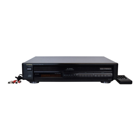
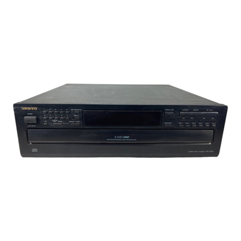
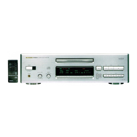
Onkyo DX-6630 User manual

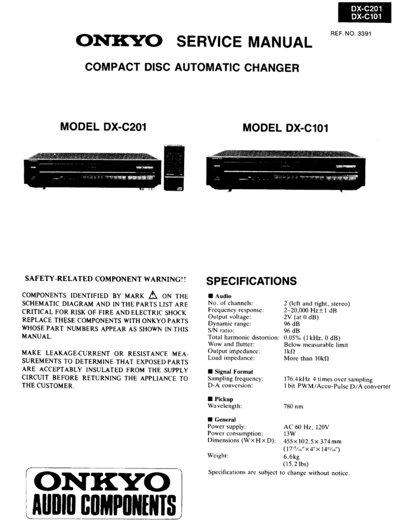
DX-6630
ONKYO.
SERVICE
MANUAL
COMPACT
DISC
PLAYER
MODEL
DX-6630
Black
and
Silver
models
SAFETY-RELATED
COMPONENT
WARNING!!
COMPONENTS
IDENTIFIED
BY
MARK
(\
ON
THE
SCHEMATIC
DIAGRAM
AND
IN
THE
PARTS
LIST
ARE
CRITICAL
FOR
RISK
OF
FIRE
AND
ELECTRIC
SHOCK.
REPLACE
THESE
COMPONENTS
WITH
ONKYO
PARTS
WHOSE
PART
NUMBERS
APPEAR
AS
SHOWN
IN
THIS
MANUAL.
|
MAKE
LEAKAGE-CURRENT
OR
RESISTANCE
MEA-
SUREMENTS
TO
DERMINE
THAT
EXPOSED
PARTS
ARE
ACCEPTABLY
INSULATED
FROM
THE
SUPPLY
CIRCUIT
BEFORE
RETURNING
THE
APPLIANCE
TO
THE
CUSTOMER,
_
|
ONKYO
AUDIO
COMPONENTS
SPECIFICATIONS
|
Signal
readout
system:
Reading
rotation:
Optical
non-contact
_
About
500~200
r.p.m.
(constant
linear
velocity)
Linear
velocity:
1.2~1.4m/s
|
Error
correction
system:
Cross
interleave
readsolomon
code
Decoded
bits:
16
bits
linear
; |
Sampling
frequency:
352.8kHz
(8
times
oversampling)
Number
of
channels:
2
(stereo)
|
ae
Frequency
response:
5Hz~20kHz
Total
harmonic
distortion:
0.004%
(at
1kHz)_
Dynamic
range:
96dB
.
|
Signal
to
noise
ratio:
100dB
:
Channel
separation:
=
90dB
(at
1kHz)
Wow
and
Flutter:
Below
threshold
of
measurability
;
Power
comsumption:
16
watts
|
eee
Output
level:
2voltsr.ms.
Dimensions
(W
x
Hx
D):
435x119x312mm
17-1/8°x4-11/16"x12-1/4”
Weight
:
4.7kg,
10.4lbs.
Specifications
are
subject
to
change
without
notice.
_

DX-6630)
DX-6630
| |
2.
Warning
lable
|
TABLE
OF
CONTENTS
This
label
is
located
on
the
arm
of
mechanism.
SPSCIHCAIONS
1)
ace
tin
me
aa
eel
add
ae
eae
]
Portection
on
eyes
from
laser
beam
during
servicing...
.
.
z
Laser
warning
labels...
2.0...
2
2
ee
ee
ee
eee
2
Caution
on
replacement
of
pickup
.............-..
4
Exploded
view-parts
list...
0.02...
ee
ee
eee
4
Exploded
View
acs
oh
ooh
goes
Se
eee
eae
eas
5
Mechanism-exploded
view.................--06-
6
PAROS
iG
a
atau
Oc
tak
Oiute
eoes
ee
Whee
ate
3a
7
Disassembling
i
os
Seiiksase
SRecbeeh
hateas
deauare
:
DANGER
=
iNvisiBLe
fase
RADIATION
Adjustment
procedures...........
ts
sata
sc
taney
Assis
Bk
Trouble
shooting
guide...
...............22005
15
AUT
10
i.
DIRECT
EXPOSURE
TO
BEAM
IC
block
diagram
and
description................
17
HW.
—HAZARDOUS
LASER
AND
se
PGSCHIDUONS
4-5.
eat
ee
en
edie
es
a5
ANDINTEFLOCK
DEFEATED
ee
chematic
diagram.
......
ity
hese
ens
eens
Bates
TTENTION
—RAYONNEMENT
ate
Waveform
of
each
section...
..........2.00000-
29
ET
ELECTROMAGNETIQUE
DANGEREUX
SI
Pc
board
view
&
Parts
list...
2...
eee
ee
ee
eee
31
OUVERT
AVEC
L’ECLENCHEMENT
OF
SECURITE
Block
diagram...
0.00.
ee
eee
eee
35
ANNULE.
$N29360911
PACKING
VIEW
ica
Oct
ow
Shere
eee
td
ed
ae
wee
36
ADVARSEL:
USYNLIG
LASERSTRALING
VED
ABNING,
NAR
SIKKERHEDSAF-
BRYDER
ER
UDE
AF
FUNKTION.
UNDGA
UDS/ETTELSE
FOR
STRALING.
Photo
1
Fig.
4
PROTECTION
OF
EYES
FROM
LASER
BEAM
DURING
SERVICING
This
set
employs
a
laser.
Therefore,
be
sure
to
follow
Laser
Diode
Properties
carefully
the
instructions
below
when
servicing.
©
Material:
GaAS/GaAlAs
ADVARSEL
ic
pNINGH
@
Wavelength:
780nm
nt
@
Emission
Duration:
continuous
;
eee
fia
Denne
merkning
er
anbragt
pa
apparatets
h@jre
side
og
indikerer
WwW
: ;
V
J
h
.
.
*
;
e
elder
ae
pee
Ret
AE
RODE
THE
TASES
sa)
held
dae
max:
Oy
at
apparatet
arbejder
med
laserstraler
af
klasse
1,
hvilket
betyder
E
TOO
CLOSELY.
IN
CASE
IT
IS
*This
output
is
the
value
measured
at
a
distance
“CLASS
1
LASER
td
dpe
|
3
:
‘
NECESSARY
TO
CONFIRM
LASER
BEAM
EMMISION,
about
1.8mm
from
the
objective
lens
surface
PRODUCT”
at
der
arwendes
laserstrater
af
svageste
klasse,
og
at
man
ikke
p&
BE
SURE
TO
OBSERVE
FROM
A
DISTANCE
OF
MORE
on
the
Optical
Pick-up
Block.
|
|
apparatets
yderside
kan
blive
udsat
for
utilladelig
kraftig
straling.
THAN
30cm
FROM
THE
SURFACE
OF
THE
OBJECTIVE
LENS
ON
THE
OPTICAL
PICK-UP
BLOCK.
APPARATET
BOR
KUN
ABNES
AF
FAGFOLK
MED
SARLIGT
KENDSKAB
TIL
APPARATER
MED
LASERSTRALER!
LASER
WARNING
LABEL
The
label
shown
below
are
affixed.
|
Indvendigt
i
apparatet
er
anbragt
den
her
gengivne
advarselsmerk-
1.
Class
1
label
(Except
120V
model)
ning,
som
advarer
imod
at
foretage
sadanne
indgreb
i
apparatet,
at
This
label
is
located
on
the
back
panel.
;
:
Pp
man
kan
komme
til
at
udsztte
sig
for
laserstraling.
AOVARSEL
USYNLIG
LASERSTRALING
VEO
ABNING,
NAR
SIKKERHEOSAF
BRYOER
ER
UDE
AF
FUNKTION
UNDGA
UDSATTELSE
FOR
STRALING
VAROITUS!
Laite
sisaltaa
laserdiodin,
joka
lahettaa
(nakyma-
tonta)
silmitle
vaarallista
lasersateilya.
“CLASS
1
LASER
PRODUCT”
Fig.
3
|
DX-6630
CAUTION
ON
REPLACEMENT
OF
PICKUP
The
laser
diode
in
the
optical
pickup
block
is
so
sensitive
to
static
electricity,
surge
current
and
etc.
that
the
com-
ponents-
are
liable
to
be
broken
down
or
its
reliability
remarkably
deteriorated.
PRECAUTIONS
1,
Ground
for
the
work-desk.
Place
a
conductive
sheet
such
as
a
sheet
of
copper
(with
impedance
lower
than
10°)
on
the
work-
desk
and
place
the
set
on
the
conductive
sheet
so
that
the
chassis.
2.
Grounding
for
the
test
equipment
and
tools.
Test
equipments
and
toolings
should
be
grounded
in
order
that
their
ground
level
is
the
same
the
ground
of
the
power
source.
Care
should
be
taken
with
the
optical
pickup.
During
repair,
carefulley
take
the
following
precautions.
(The
following
precautions
are
included
in
the
service
parts).
3.
Grounding
for
the
human
body.
Be
sure
to
put
on
a
wrist-strap
for
grounding
whose
other
end
is
grounded.
Be
particularly
careful
when
the
workers
wear
synthetic
fiber
clothes,
or
air
is
dry.
4,
Select
a
soldering
iron
that
permits
no
leakage
and
have
the
tip
of
the
iron
well-grounded.
5.
Do
not
check
the
laser
diode
terminals
with
the
probe
of
a
circuit
tester
or
oscilloscope.
The
optical
pickup
is
sensitive
to
static
electricity,
surge
currents,
and
other
high
electrical
noise.
and
because
there
is
the
possibility
of
damage
to
performance.
in
the
handling
of
the
pickup.
the
utmost
care
must
be
taken,
particularly
with
regard
to
static
electricity.
|.
When
checking
the
laser
terminal.
avoid
making
connections
using
the
probes
of
a
tester
or
oscilloscope,
or
an
ordinary
power
supply.
2.
When
replacing
the
optical
pickup,
first
short
the
LD
terminals
and
remove
the
connector.
Also.
when
attaching
the
new
optical
pickup.
after
attaching
the
connector.
unsolder
the
LD
terminals.
EXPLODED
VIEW-PARTS
LIST
REF.NO.
PART
NO.
DESCRIPTION
1
27100190
Chassis
2
27121238-1
Back
panel
4
27300750
¢\
Bushing,
cord
(Strainrelief)
5
27190266
KGLS-12R,
Holder
6
28140946
Cushion
7
27273112
Joint,
power
9
272702144
Spacer
(Main
circuit
pc
board)
ll
27190706B
Holder,
mechanism
12
28140928
t4
25
X25,
Cushion
13
27141340
Bracket
L
15
830440109
4TTC+10C(BC),
Tapping
screw
16
834430088
3TTS+8B(BC),
Tapping
screw
17
833430080
3TTP+8P(BC),
Tapping
screw
18
831130088
3TTW~+8B,
Tapping
screw
19
834430108
3TTS+10B(BC),
Tapping
screw
20
833426060
2.6TTP-6P(BC),
Tapping
screw
26
27110477
Front
bracket
ass’y
<B>
27110477-1
Front
bracket
ass’y
<S>
ol
28184429
Top
cover
<B>
28184430
Top
cover
<S>
ag
834430088
3TTS+8B(BC),
Tapping
screw
51
1H079121
Front
panel
ass’y
<B>
1H080121
Front
panel
ass’y
<S>
38
27211085-2
Tray
panel
<B>
272110853-1
Tray
panel
<S>
71
28191512
Clear
plate
12
833430080
3TTP+8P(BC),
Tapping
screw
74
27270255
Spacer
76
27175153
Leg
Optical
pickup
LD
terminals
Fig.
6
NOTE:
<B>:
Only
Black
Models
<S>:
Only
Silver
Models
77
834430088
3TTS+8B(BC),
Tapping
screw
81
801364
Special
screw
82
801414
Special
screw
83
27175011C
Leg
(Cushion)
85
29360911
Label,
caution,
laser
87
29360687
Label
CLASS
1
88
28175158A
Insulator
plate
P921
253148
or
A
AS-CEE
250V
2.5A,
253130
Power
supply
cord
T901
2300385B
‘\NPT-1015G,
Power
transformer
U1
1H073542-1A
NAAR~-3542-1A,
Main
circuit
pc
board
ass’y
UZ
1H073543-1
NADIS-3543-1,
Display
circuit
pc
board
ass’y
U3
1H073544-1
NAAF-3544-1,
Headphone
amplifier
pe
board
ass’y
U4
1H073545-1
NAPS-3545-1,
Power
supply
pc
board
ass’y
U5
1H073546-1
NAETC-3546-1,
Syncro
terminal
pc
board
ass’y
L901
230907
TR-16-8-16,
Core
(2nd
side
of
power
transformer)

EXPLODED
VIEW
NOTE:
THE
COMPONENTS
IDENTIFIED
BY
MARK
AA
ARE
CRITICAL
FOR
RISK
OF
FIRE
AND
DX-6630
|
Fig.
7
ELECTRIC
SHOCK.
REPLACE
ONLY
WITH
PART
NUMBER
SPECIFIED.

f
DX-6630
MECHANISM-EXPLODED
VIEW
PARTS
LIST
DX-6630
REF.NO.
PART
NO.
DESCRIPTION
REF.NO.
PART
NO.
DESCRIPTION
1
27100188A
Mechanism
chassis
22
28140941
Cushion
2
27301201
Turntable
23
28140947
Cushion
3
24502243
Spindle
motor
25
27300942C
Cam
gear
4
28140948
Tube
26
27300943
Pulley
gear
5
82142003
2P+3F(BC),
Pan
head
screw
a7
27300944A
Gear
6
24110001
KSS-152A,
Optical
pickup
28
1H025901
Tray
motor
ass’y
7
27260222
Shaft
©
30
27301079
Belt
8
27301191
Rack
A
31
82143004
3P+4FN(BC),
Pan
head
screw
10
1H073902
Slide
motor
ass’y
_
32
27301107
Cushion,
rubber
ll
27141230
Bracket,
holder
34
25065321
NMS-1113,
Microswitch
(S002/S003)
12
834430068
3TTS+6B(BC),
Tapping
screw
35
25065322
NMS-1214,
Microswitch
(S001)
13
831126060
2.6TTW+6P,
Tapping
screw
36
2000733B
NSAS-6P689,
Socket
ass’y,
motors
14
831430100
3TTW+10P(BC),
Tapping
screw
37
2000734B
NSAS-6P690,
Socket
ass’y,
15
833420068
2TTP+6P(BC),
Tapping
screw
.
microswitches
16
833426060
2.6T
TP+6P(BC),
Tapping
screw
(38
2000952
NSAS-8P904,
Socket
ass’y,
white
18
27301190
Arm
39
2000951
NSAS-8P903,
Socket
ass’y,
red
19
27300848A
Cap
CH
4]
27301192A
Rack
B
20
27180341A
Spring
42
27180426
Spring
21
27301202A
Disc
tray
ass’y
43
27301189
©
Cap,
arm
44
27300849C
Holder,
cap
DISASSEMBLING
PROCEDURES
Method
for
removing
the
tray
Lug
for
lock
Fig.
10
3.
Insert
a
small
flat-bladed
screw
driver
into
the
hole
section
of
the
right
side
of
the
back
of
the
tray,
and
push
the
lug
used
for
locking
the
tray
to
bring
the
tray
i
Fa
|
to
the
front.
I.
Set
the
position
so
that
the
cam
gear
and
gear
are
disengaged.
CAUTION:
When
inserting
the
tray,
the
cam
gear
and
2.
Pull
the
tray
to
the
front.
gear
parts
are
not
in
the
meashing
position.
Method
for
removing
disc
motor
.
Remove
the
tray.
Cut
.
Remove
the
holder,
then
remove
the
arm.
.
Remove
the
3
screws
that
fasten
the
mechanism
chassis
to
the
main
chassis.
.
Cut
the
turntable
platter
with
a
nipper.
.
Remove
the
soldering
of
the
disc
motor,
and
remove
the
2
fastening
screws.
6.
When
inserting
the
turntable
platter
onto
the
motor
shaft,
hold
the
platter
at
a
right
angle
to
the
motor
shaft
and
push
it
onto
the
shaft
until
it
touches
the
f
bottom.
Wh
an
te
LUBLICATION
A
:FLOIL
G902S
PART
NO.
260447
Cut
NOTE:
Height
of
turntable
platter.
See
page
14.

Focus
;
Lon
|
Focus
drive
1
L
*
eel
Focus
offset
DX-6630
CIRCUIT
DESCRIPTIONS
+5V
Focus
error
(FE)
signal
(A+C)—(B+D)
Pane
ci28
tek
R133
|
+5
VA
P105
a
:
ie
dig
Risa
|
Petts
4
101
1RIG2
3
=
:
j
demas
eqn
eanann
Outs
Crh
epeiphe
nea
GS
cumin
dene
ae
ene
eee
{
H
BS
orgs
U
ae
On
ao7
A
|
|
(focus
zero
*
On
RIZ3
cross)
~—s
[Phrase
\_RI32
i
8)
correction
|b
>—(5)“{2)
DD
(8)
}
!
RI
\
72
cla
;
|
f
ees
7a
i
I
ee
mere
meee
seats
ey
champs
None
Si
“fs
RHO
RIG
Optical
pick-up
‘and
offset
adjustment
1.
Focus
servo
circuit
From
the
optical
pickup
objective
lens,
the
emitted
laser
beam
is
focused
on
the
disc
reflecting
surface,
an
this
circuit
controls
the
movement
of
the
lens
up
and
down.
1-1.
Error
detecting
circuit
The
error
is
detected
by
means
of
the
astigmatic
aberration
method
and
obtains
its
focus
error
signal
from
the
optical
pickup
output
signal
(A+C)—(B+D).
|
The
individual
signals
(A+B)
and
(C+D)
input
to
pins
7
and
8
of
Q102
are
subtracted
by
means
of
the
IC
internal
op
amp,
and
from
pin
19,
the
F.E.
signal
is
output.
Also,
in
order
to
eliminate
the
focus
error,
offset
adjustment
is
carried
out
by
the
semi-fixed
resistor
R110
of
pin
18
of
Q102.
1-2.
Phase
correction
and
driver
circuit
By
means
of
the
semi-fixed
resistor
R122,
the
gain
adjusted
F.E.
signal
passes
by
way
of
the
phase
correction
circuit
from
pin
48
of
Q104,
and
from
pin
5S
of
Q104
to
the
driver
Q107,
and
is
feedback
to
the
coil
used
for
driving
the
optical
pickup
KSS-152A
objective
lens.
In
addition,
there
are
the
FS4
servo
ON/OFF
switch
and
FS3_
phase
characteristic
selector
switch.
1-3,
Focus
zero
cross
circuit
and
focus
search
circuit
In
order
to
have
mandatory
drive
of
the
objective
lens
in
the
capture
range
of
only
10um
at
the
focus
point
it
is
necessary
to
turn
off
the
above
mentioned
FS4
and
close
the
servo
loop.
The
timing
diagram
for
that
operation
is
shown
in
Fig.13.
The
triangular
wave
generated
by
means
of
the
focus
search
circuit
internal
to
Q104
shifts
the
objective
lens
up/down
direction,
and
at
the
correct
focus
point,
the
fall
of
F.E.
signal
is
detected
by
the
focus
zero
cross
(FZC)
circuit
to
close
the
servo
loop.
At
this
time,
it
is
necessary
that
the
focus
OK
(FOK)
signal
be
in
the
high
level.
In
Fig.13,
the
dotted
line
is
the
waveform
of
the
focus
capture
failure.
Focus
gain
————
adjust.
RUS
Focus
servo
ON/OFF
adjustment
Preamp.,
error
detector,
Gain
adjustment
Phase
switching
Focus
search
switching
Facus
search
circuit
and
driver
Phase
correction
and
zero
cross
detector
Fig.
12
Focus
servo
circuit
Servo
ON
“
5
about
3.5V
Focus.drive
output
2
Capture
|
start
F.E.
\
“
5V_
|
x
FOK
|
ne
eee
5V
FZC
|
|
SENSE
.
terminal
ov
Fig.
13
Capture
operation
of
focus
R
GND
P105
#1
Test
point
GND
FO
1Vidiv.
(Lower)
7.
O.5V/div.
(Upper)
2ms/div.
Focus
signal
Photo
2
Tracking
coil
EB
|
|
i
"Smet
narnhomel
KSS-I52A)
Tracking
drive
output
RI08——L_
RIO9
=
Tracking
offset
adjustment
Preamp,
error
detector
Gain
Sea
ee
é
and
offset
adjustment
Optical
pick-up
2.
Tracking
servo
circuit
On
the
disc
at.a
pitch
of
1.6um,
the
laser
beam
accurately
traces
the
center
of
the
pits
cut
into
the
disc,
and
this
is
the
control
circuit
that
shifts
the
objective
lens
in
the
radial
direction.
2-1.
Error
detection
circuit
The
F-E
is
obtained
from
the
tracking
error
(T.E.)
signal
by
~~
means
of
a
3
beam
method.
The
F.E.
signal
input
to
pins
10
and
11
of
Q102
is
subtracted
internally,
and
is
output
as
the
T.E.
signal
from
pin
20.
R108
is
the
semi-fixed
resistor
control
for
tracking
offset.
2-2.
Phase
correction
and
driver
circuit
The
T.E.
signal
adjusted
for
gain
by
means
of
the
semi-fixed
resistor
R125
passes
through
the
phase
correction
circuit
from
pin
45
of
Q104,
and
from
pin
11
by
way
of
driver
Q107
objective
lens.
TM1
and
TM7
are
used
as
the
tracking
servo
ON/OFF
switches,
and
TG!
and
TG2
respectively
are
used
as
the
phase
selector
and
gain
selector
switches.
wer
GND
P105
#3
0.5V/div.
0.5ms/div.
Tracking
signal
Photo
3
adjustment
135
Tracking
error
(T.E)
signal
R62
Servo
ON/OFF
Tz¢
(tracking
:
zero
cross)
(9)
a
Track
kick
circuit
and
driver
Phase
correction
and
tracking
zero
cross
detector
Fig.
14
Tracking
servo
circuit
2-3.
Tracking
zero
cross
and
track
kick
circuit
At
the
time
the
head
comes
out
and
when
there
is
manual
fast
forward,
in
the
event
that
is
it
necessary
to
skip
over
the
track
being
traced,
the
T.E.
signal
receives
a
kick
pulse,
and
by
mens
of
this,
shifting
of
the
objective
lens
can
be
achieved.
TM3
and
TM4
respectively
are
the
switches
for
providing
the
forward
and
reverse
direction
kick
pulses.
Also,
the
tracking
zero
cross
(TZC)
circuit
counts
the
number
of
—
tracks
skipped
over
and
produces
the
signal
in
order
to
determine
the
timing
of
the
servo
ON/OFF.
The
ON/OFF
command
for
these
switches
is
output
from
the
microcomputer.
0.2
us/div.
0.5mV/div.
Signal
HF
(RF)
Play
the
track
2
of
YEDS-18.
Photo
4

Ci04 PIOS
7
!
RIO6
RIOS
Boe
S
eneeinananetiicene:eadiessene
Teese
tiencecdin
a
goes
high,
the
servo
and
gain
are
controlled,
and
the
circuit
prevents
a
sound
outburst.
4.
APC
circuit
| |
By
means
of
feedback
from
the
monitor,
this
circuit
controls
the
light
output
due
to
a
bad
condition
resulting
from
the
temperature
characteristic
of
the
laser
diode.
For
the
pin
29
LDON
(laser
diode
ON)
signal,
when
the
APC
ON/OFF
control
signal
is
LOW,
the
laser
is
emitted.
5.
CLV
servo
circuit
In
the
compact
disc
there
is
a
CLV
system
(constant
linear
velocity),
and
at
the
replay
position,
because
the
disc
rotary
speed
varies,
the
clock
is
taken
out
of
the
HF
signal,
and
HF
signal
(eye
pattern)=
A+B+C+D
HF
—10—
the
PLL
circuit
and
its
clock
must
be
synchronized
to
Asymmetry
signal
control
the
spindle
motor.
component
of
the
tracking
driver
output
is
amplified
and
fed
to
the
motor,
but
when
the
head
is
extended,
switches
TMS
and
TM6
internal
to
Q104
control
the
ON/OFF.
Fig.
17
PLL
circuit
DX-6630
4
5-2.
Spindle
motor
control
circuit
The
output
of
the
phase
comparator
(MDP)
and
frequency
comparator
(MDS)
from
pins
3
and
4
of
Q109
is
fed
to
pins
34
and
36
of
Q104.
Also,
the
spindle
motor
ON/OFF
2
A+Cc
@
NO
va
>
reyKey='
5-1.
PLL
circuit
|
x
i
As
shown
in
Fig.
6,
for
the
phase
comparator,
in
Q109
the
signal
(MON)
from
pin
2
of
Q109,
and
the
phase
selector
qe
eS
RI
Ril2
lt
i
i-fi
ignal
(FSW)
f
in
1
tput
and
fed
to
pin
36
of
ee
y
<i
G6)
(6)
LPF
and
VCO
are
each
built
into
Q104.
The
semi-fixed
signa
rom
pin
1,
are
output
an
O
pin
50
0
54D
ae
|
Va
Coote,
|
A
resistor
R147
is
the
control
for
adjusting
the
8.6436
MHz
QI104.
After
these
signals
are
processed
in
Q104,
they
are
C103
|
CHO
Cll!
R
free
run
frequency
(WFCK
=
7.35
KHz).
passed
from
pin
39
through
the
driver
Q108,
and
are
|
>
2)
mel
Or)
ie
Oma
supplied
to
the
spindle
motor.
|
Scales
Pee
EFM
signal
Ri27
|
Re
Mir
Qt:
AA
a
>
sional
ciieant
22)
:
MIR
Q109
Q104
isa
aoe
3.
HF
(RF)
amplifier
r
|
f
.
|
a
=
Satddlaaigror
This
circuit
feeds
the
A+B+C+D
to
the
amplifying
and
form
|
rt
eens)
Or
siene!
FSW
&
ON/OFF
Ri29
processing
circuit
together
with
the
data
HF
(RF)
signals!
|
CIOs
MON
nal
|
he
SP
due
to
the
pits
cut into
the
disc,
checks
the
servo
condition,
I
ni
|
Sams
BS
69
iad
°
S
and
transmits
that
data
to
the
microcomputer.
Re
ee
MDP
CPF
R128
oe
I
see
,
et
|
Focus
OK
MDS
(4)
|
a
3-1.
HF
amplifier,
waveform
shaping
circuit
i
circuit
e8)
Pocus
OK
|
=
The
At+C
and
BtD
signals
input
to
pins
7
and
8
of
cee
IRII3
ee
omens:
i;
|)
Sere
NSS pee
a
ee
re
ee
a
Q108
x
FAQS
-added
by
the
op
amp,
and
the
HF
signal
(eye
pattern)|
|
ee
AtB+C+D
is
output
from
pin
2.
The
HF
signal
then
passes
|
z
ciao
oe
through
C103
and
R118
entering
at
pinl,
is
shaped
by
Ci39
.
:
srcui
;
Lm
|
Fig.
18
dle
motor
control
circuit
means
of
the
comparator,
and
becomes
the
EFM
signal
rp
bie
@
1)
DFCT
=
een
nary
eres
which
is
output
from
pin
27.
l
|
a
ae
es
‘|
Fast
forward
In
the
comparator
threshold
value,
the
EFM
signal
low
thr
4
Defect
signal
|
Pe
region
component
ASY
(asymmetry)
is
input
from
pin
ee
(5)}-(6)-—-
RI36
:
>
TMG
and
control
is
achieved
by
this
means.
Cio?
Fig.
15
HF
amplifier
circuit
cizj
——~
Fast
rewind
a
|
RIGO
RI4I
|
3-2.
MIR
circuit,
FOK
circuit,
and
DFCT
circuit’
~~~
oe
gio7
VA,
Ny
8
:
After
the
HF
signal
is
processed
the
detection,
shaping,
etc,
Driver
—_
Ci)
FA
LEMS
A
SLD
respectively
the
MIR,
FOK,
and
DFCT
signals
are
output
LPF
is
Slide
motor
from
pins
22,
28,
and
21,
7
RI37
EO)
e
6
t1@
UW
R135
oS
©
ot
8
A
ae
7
ad
3-2-1.
MIR
(mirror)
signal
ue
|
ciS2
|
When
the
head
is
extended,
at
the
time
the
signal
becomes
ry
A
|
R138
af
|
Saari
P104
high
at
the
disc
track
and
between
tracks,
the
number
of
Ww
Ls)
ie,
Cea
NOE
L
tracks
is
counted,
and
this
is
used
for
determining
the
YZ
M.0
Q104
|
timing
for
the
ON/OFF
of
the
servo,
—3
>
hs
a
:
SGiOEL”
Driver
.
-5
|
|
i
ee
i
Fig.
19
Slide
motor
circuit
3-2-2.
FOK
(focus
OK)
signal
Monitor
output
P102
|
xss-isza
This
signal
goes
high
at
the
time
the
focus
servo
is
required.
pail
6
Side
metarcivcuit
Refer
to
1-3}
4
SSerone?
Fig.
16
APC
circuit
This
circuit
controls
the
slide
motor
which
is
used
for
3-2-3.
DFCT
(defect)
signal
moving
the
optical
pickup
from
inside
the
disc
to
the
If
there
is
a
defect
(scratch,
dirt,
etc.)
in
the
disc,
this
signal
CUTE
ee
Dotnet
Play
eee
iy
res
ow
Seen
Q104
#32
PLCK
1V/div.
(Upper)
2V/div.
(Lower)
0.1
us/div.
Photo
5
5
ee

|
DX-6630
ADJUSTMENT
PROCEDURES
Instruments
required
Dual
trace
oscilloscope,
Frequency
counter,
AF
oscillator,
Test
disc
(SONY
YEDS-18),
AC
voltmeter,
Jitter
meter,
Sockets
P106
&
P107
(Part
No.
25050089)
P105
(Part
No.
25050138)
1.
VCO
frequency
adjustment
Connect
the
frequency
counter
to
terminal
P107.
Turn
the
power
switch
to
ON.(No
load
the
disc.)
Adjust
R147
until
the
frequency
counter
reading
becomes
4322
+SkHz.
|
After
adjustment,
disconnect
the
frequency
counter.
2.
Focus
offset
adjustment
Load
the
test
disc
YEDS-18
on
the
tray
and
play
the
track
2.
Connect
the
oscilloscope
or
jitter
meter
to
terminal
P106.
(Oscilloscope)
;
Adjust
R110
until
a
clear
trace
of
waveform
pattern
as
shown
photo
1
appear
on
the
oscilloscope.
When
the
amount
of
jitter
is
broad,
set
R110
to
mechanical
center.
(Jitter
meter)
Adjust
R110
until
the
jitter
meter
reading
becomes
minimum.(Less
than
10ns.)
After
adjustment,
disconnect
the
oscilloscope
or
jittter
meter.
Frequency
P107
counter
Use
the
high
impedance
probe
more
than
10
MQ.
HF
+
,
Oscilloscope
range
Vertical
:
0.2V/div.
-
Holizontal
:0.5
ps/div.
‘Oscilloscope
Photo
6
3.
Tracking
offset
adjustment
Play
the
track
2
of
test
disc.
Turn
R125
to
minimum
position.(Counter
clockwise)
Connect
the
oscilloscope
between
pin
3
(TR)
of
P105
and
pin
2
(GND)
of
P106.
Adjust
R108
until
the
center
of
tracking
error
signal
on
the
oscilloscope
becomes
GND
level.
Turn
R125
to
the
mechanical
center.
After
adjustment,
disconnect
the
oscilloscope.
Oscilloscope
Vertical
:
50mV/div.
Holizontal
:
0.2
ps/div.
DC,
Ground:
Center
—12—

4.
Focus
gain
adjustment
Set
the
output
of
AF
oscillator
to
800Hz,
1~1.5Vp-p.
Play
the
track
2
of
test
disc.
Connect
the
oscilloscope
and
the
AF
oscillator
as
shown
_
below.
owe
dew
ee
|
-
Photo
8
Adjust
R122
until
800Hz
components
of
channels
1
and
2
on
oscilloscope
become
same
level.
After
adjustment,
disconnect
the
AF
oscillator
and
the
oscilloscope.
5.
Tracking
gain
adjustment
Set
the
output
of
AF
oscillator
to
1.2kHz,
1~1.5Vp-p.
Play
the
track
2
of
test
disc.
Connect
the
oscilloscope
and
the
AF
oscillator
as
shown
below.
[a
A=B
Photo
9
Adjust
R125
until
1.2kHz
components
of
channels
1
and
2
on
oscilloscope
become
same
level.
After
adjustment,
disconnect
the
AF
oscillator
and
the
oscilloscope.
|
6.
MSB
adjustment
Play
the
track
2
of
test
disc.
Read
the
output
signal
and
regard
it
as
0
dB.
Then,
play
the
track
17.
a
Adjust
R403
(R404)
so
that
the
output
level
becomes
—60dB.
NOTE:
(__):
R
channel
.
[p
---L..
P1005
-
Oscilloscope
AF
oscillator
GND
CH
1
CH
2
Vertical
+
0.5V/div..
Holizontal:
1
ms/div.
AF
.
258
“Oscilloscope
Site
Bieseee
Ba
laatiee
ae
oscillator
GND
CH1
CH2
Vertical
:
0.5V/div.
_
Holizontal:
0.5
ms/div.
—13—
MECHANISM
ADJUSTMENT
Height
of
turntable
platter.
Turntable
platter
10.5
+
0.1mm
Chassis
Fig.
21
Tray
motor
8.2
+
0.1mm
Fig.
23
—~14—
vco
PIOS
RI25
Ee
1
TRACKING
GAIN
RI22
RIO
FOCUS
FOCUS
GAIN
OFFSET
Fig.
20
ADJUSTMENT
POINT
Slide
motor
22.6~22.8mm
Fig.
22
1B)
Ge
loxe
1
@)

TROUBLESHOOTING
GUIDE
Symptom:
Defective
reading
(No
RF
signal
emitted)
Load
the
disc
on
the
tray,
press
OPEN/CLOSE
key
and
close
the
tray.
But,
the
total
number
of
tunes
are
not
indicated
on
the
fluorescent
indicator
tube.
Does
tray
open
for
some
time?
No
Does
pickup
returned
to
innermost?
Is
the
$003
start
switch
ON?
Yes
Continuously
ON
Method
for
checking
S003
Zonnect
oscilloscope
to
pin
3
of
P103,
does
it
momentarily
go
to
OV.
1.
Remove
the
top
cover.
2.
Does
the
disc
turn
clockwise?
.......
Yes......
Next
page
No
....
Remove
the
bracket
holder
and
arm
ass’y.
Check
the
following
when
turning
on
power
without
the
disc.
Chucking
mechanism
Chucking
limit
switch
(IN
switch
S002)
+-++
Tray
does
not
close.
....
Confirm
that
the
slide
motor
runs
smoothly
with
the
tester
(ohm
range)
or
1V
DC
applied
to
both
ends
of
the
motor.
....
Bring
the
pickup
to
the
outermost
circumference.
After
power
source
is
applied
to
SLD
terminal,
is
the
voltage
-2V
to
4V?
Yes
...
Slide
motor
defective
No
...
Q104
pin
14
(check
at
leads
of
R139):
when
low,
Q104
is
defective,
if
pulse
emitted
at
CLK
(J158),
XLT
(J157),
DATA
(J160)
and
when
not
emitted
at
0104,
Q107
is
defective.
GND
| |
GND
G
Check
rack
PU
movement
Slide
motor
circuit
S003:
Start
switch
Q751-»Q104—0107
Not
ON
Yes
$003
ov
Fig.
24
CLK(J158)
XTL(J157)
DATA(J160)
L
_5y
STOP:
5V
STOP:
5V
STOP:
0V
OFF
ON
OFF
Does
No
Optical
pickup
(Q101
ON,
pickup
ON
with
collector
at
2V
laser
APC
circuit
(Pin
32
of
Q751
LSR
OV,
Q101
base
low
light?
check).
P102
socket
insertion
defective.
Q109
oe
When
the
START
switch
is
ON
continuously,
the
laser
is
lit
80
Yes
continuously,
and
the
focusing
coil
does
not
go
up
and
down
24
1
sides.
Check
the
gear
meching.
Does
the
No
Does
a
search
voltage
of
Yes
sees
object
lens
—2V
~3V
output
at
the
Optical
pickup
defective
J156
XRST
move
to
up
and
focus
drive
output
P102
socket
insertion
J157
XLT
down
sides?
test
point
FO?
defective
3158
CLK
J159
S.
SW
|
J160
DATA
Yes
J161
SENSE
Q104,7
focus
search
circuit
Fig.25
test
point
No
Does
the
disc
start
to
turn
clockwise?
optical
pickup
-®
Play
the
track
2
of
test
disc.
(YEDS-18)
ves
High
MON
Does
pin
2
of
Q109
turn
at
Peis
an
7
high
level?
Low
Hoes
the
test
Low
point
GFS§
turn
at
the
high
level?
High
Q107
or
Q109
trouble
Asy
PLL
circuit
trouble
of
Q102
turn
at
Spindle
motor
control
|
circuit
trouble
Does
pin
26
of
of
Q102
turn
at
NOTE:
There
is
the
possibility
that
the
pickup
lens
is
so
dirty
that
it
is
impossible
to
read.
Clean
with
a
lens
cleaner.
FOK
Low
Focus
servo
circuit
or
adjustment
miss
Does
pin
26
of
Je
@
Use
the
high
impedance
probe.
(10:1)
lelote
RISK
ste
#008
FOK
:
Be
RF
signal
Tracking
signal
en
ah
Low
P106
pin
2
(HF)
P105
pin
4
(HF)
at
high
level:
V:
50mV/div
V:
20mV/div
:
H:
0.5S/div
Photo
10
H:
0.5mS/div
High
level
more
than
1
sec.
Is
the
No
tracking
OK?
os
Tracking
servo
circuit
trouble
or
adjustment
miss
Contirm
the
HF
signal
(eye
pattern)
or
tracking
singal.
Yes
*
2.5V
HF
waveform
sharp
high
tevel?
circuit
trouble
=
2.5V
Higher
speed
or
lower
speed
Rotation
speed
of
disc
OK
:

DX-6630
Q104
CXA1082BQ
(Servo
Signal
Processor)
_
IC
BLOCK
DIAGRAM
AND
DESCRIPTIONS
—
Q102
{
CXA1081M
(RF
Amp)
wv
$s
<8)
12
U
DATA
REGISTER
INPUT
SHIFT
REGISTER
AODORESS-
OECOOER
MIAROR
HOLO
AMP
SEQUENCER
OUTPUT
DECODER
OIFFERE~
NTTAL
AMP
TGI2
0
TM
IA7
PS
IA
‘
z
g
ie
¥
2
@
TRACKING
ERROR
BOTTOM
HOLO
AMP
REF
ERENCE
CURRENT
}
RF
1-V
AMP
(1)
2)
N
&
Fig.
26
Rei
|
Input
termina
of
output
danaleC
RF
stmming
|
4g
|
ccy_|
Defect
botiom
hold
output
txmint
|
:
[ne
|
eemibatot
RF
mening
amples
=
|g
frag
Non-inversion
bias
terminal
of
focus
error
amplifier
P/N
:
Function
Insert
the
capacitor
between
this
terminal
and
2
FGD
|
pin
3
when
drop
the
high
frequency
gain
of
focus
servo
21
22
3
FS3
Switching
terminal
of
high
frequency
gain
of
23
focus
servo
24
|
25
4
|
FLB
ck
Input
terminal
of
phase
comparator
output
PDO
Input
terminals
for
microcomputer
and
interface
Time
constant
switching
terminal
when
raise
the
low
frequency
gain
of
focus
servo
Flow
the
current
to
decide
the
focus
search,
track
CMR
adjustment
of
focus
error
amplifier
9
Seer
cn
$$
|
3
|
FEO
jump,
and
kick
height
witching
terminal
of
P-
N-SUB
of
LD
:
~~
\
Operation
amplifier
output
terminals
for
power
(laser
diode)
9
|
Fe
Output
terminal
of
focus
error
amplifier
Titer
drive
30
vcop
|
VCO
free
run
frequency
is
proportion
to
resistor
:
:
value
between
pins
30
and
31
-
i
6
;
FE-
Inversion
input
terminal
of
focus
amplifier
32.
|
C864
|
VCO
(8.64MHz)
output
terminal
Input
terminal
of
APC
PD
(Pin
diode)
amplifier
DEFECT!
Output
terminal
of
defect
comparator
|
inversion
input
terminal
of
RF
I-V
amplifier
(1)
;
;
7
=
SRCH
|
ee
to
make
the
focus
34
MDP
Te
ae
\
Time
constant
terminal
for
high
frequency
gain
|
LPF
time
constant
terminal
of
CLV
servo
error
;
TG2
|
switching
of
tracking
36
|
Fow
signal
Inversion
input
terminal
of
spindle
drive
amplifier
Connection
terminal
of
capacitor
for
mirror
PD?
Inversion
input,
terminal
of
RF
[-V
amplifier
(2)
23
hold
Non-inversion
input
of
mirror
comparator
;
Connect
to
B+D
of
PIN
diodes.
Connection
terminal
of
capacitor
for
defect
bottom
hold
DGND
|
Connect
to
GND
Auto
asymmetry
control
input
terminal
.
Connect
to
GND.
12
TA-
Inversion
input
terminal
of
tracking
amplifier
38
SPDL—
Inversion
input
terminal
of
F
I-V
amplifier
Connect
to
F
of
PIN
diode.
Non-inversion
input
terminal
of
sled
amplifier
Inversion
input
terminal
of
sled
amplifier
iS
|
SL-
Inversion
input
terminal
of
E
I-V
amplifier
Input
terminals
for
microcomputer
and
interface
Connect
to
E
of
PIN
diode.
16
SSTOP
Limit
switch
ON/OFF
detector
signal
terminal
{
Output
terminal
of
E
I-V
amplifier
!
for
disc
innermost
position
detector
Output
terminal
of
EFM
comparator
|
Feedback
input
terminal
of
E
I-V
amplifier
13
El
Gain
adjustment
of
E
I-V
amplifier
Output
terminal
of
FOK
comparator
,
DC
voltage
output
terminal
of
(Vcc
+
Vee)/2
LD
ON
|
ON/OFF
switching
terminal
of
laser
diode
15
cc?
Input
terminal
from
defect
bottom
hold
output
:
signal
via
the
coupling
capacitor
Positive
power
supply
—17—
Tracking
error
signal
input
terminal
17.
|
ESET
Terminal
of
peak
of
phase
compensation
of
focus
tracking
and
of
setting
of
LPF
|
46
|
TZc
Tracking
zero
cross
comparator
input
terminal
18
|
SENS
|
Output
terminals
for
microcomputer
and
47
ATSC
Window
comparator
input
terminal
for
ATSC
20
C.OQUT
|
interface
detection
|
27
|
BW
Time
constant
terminal
of
loop
filter
Focus
error
signal
input
terminal
aes

Q401,
0402
PCM-56P-L
(D/A
Converter)
on
mA
oO
BP
WwW
DY
YH
Q109
CXD11300Q
(Digital
Signal
Processor)
(S)
SCOR
SUBCODE
ASY
SYNC
DETECTOR
EFM
(S)
>
23
BIT
eae
it
SHIFT
REGISTER
GFS
(8)
ae
LOCK
(7)
FSW
on
CLY
SERVO
SYNC
BET
J
CONTROL
INSERTER
MON
VCO
0
(8)
VCO
CIRCUIT
vco1(9)
TIMING
INTERPOLATOR
GENERATOR
XTAO
(64)
X?
TAL
CIRCUIT
xTA
1
G3)
TIMING
DIGITAL
FILTER
TRACKING
AM
ADDRESS
CNIN
()—")
couNTER
|
GENERATOR
nw
FH
w
38°48
Pal
pa
2
za
4
>
Sx
q
V
uw
<<
i
¢
oO
ace
w
~
K
i
SUBCODE
DEMODULATOR
Logic
voltage
(+)
Not
used
Clock
input
Latch
enable
input
Data
input
Logic
voltage
(—)
53
x
m@
Ww
w
if
EFM
DEMODULATOR
[>
ERROR
DETECTOR
CORRECTOR
|
9
10
}11)
SJ
12
SUBCODE
Q
REGISTER
DIGITAL
OUT
VOUT
RF
ANA
GND
13)
1OUT
i
MSB
ADJ
|
VPOT
+Vec
SELECTOR
re
Vo
DX-6630
DX-6630
|
Output
|
Feedback
register
Operation
amplifier
input
Analog
ground
Current
output
MSB
adjustment
ter
minal
Meter
terminal
|
Analog
power
supply
(+)
29
0808
Cs
37
DBOT
Voo
Fig.
29
Symbol
RAWE
RACS
C4M__|
Divider
output
of
crystal.
f=4.2336MHz
Function
Pin
No.
Write
enable
signal
output
to
external
RAM
Chip
selector
signal
output
to
external
RAM
[rnc
[Smee
[Penewon
Lae
FSW
Time
constant
switching
output
terminal
of
49
ON/OFF
control
output
terminal
of
spindle
motor
output
filter
of
spindle
motor
,
5
Drive
output
terminal
of
spindle
motor.
52
3
Rough
control
when
mode
CLV-S
and
phase
control
when
mode
CLV-P
53
XTAI
|
Input
terminal
of
crystal
oscillator
Drive
output
terminal
of
spindle
motor.
XTAO
|
Output
terminal
of
crystal
oscillator
Speed
control
when
mode
CLV-P
ecceeait
55
MDI
2
57
MD3
LF)
—_
Vss
Ground
EFM
signal
input
terminal
from
RF
amplifier
Mode
switching
input
terminals
ps
|
asy
|
SLOB
|
Code
switching
input
of
audio
data
output.
GFS
sampling
terminal
/
Mode
switching
input
of
audio
data
output.
Serial
output
at
low
level.
59
PSSL
VCOO
VCO
output
terminal.
8.6436MHz
when
lock
pe
|
rs
Parallel
output
at
high
level
to
EFM
signal
PTR
Control
output
for
aperture
correction.
VCOI
{|
VCO
input
terminal
High
level
when
Rch.
High
level
when
Lch.
Phase
comparator
output
terminal
of
EFM
]
signal
and
VCO/2
DAO1 DAO]
(LSB
of
parallei
sound
output)
output
when
PSSL
=
H.
CIF1
output
when
PSSL
=
L
DAQ2
output
when
PSSL
=
H.
microcomputer
;
;
DA0Q3
output
when
PSSL
=
H.
14
XLT
|
Latch
input
terminal
from
microcomputer
C2F1
output
when
PSSL
=
L.
DA04
output
when
PSSL
=
H.
C2F2
output
when
PSSL
=
L.
Output
terminal
to
control
the
slice
level
of
EFM
signal
10
62
63
DAO2
J
o)
re
nw
DAO3
15
DATA
|
Serial
data
input
terminal
from
microcomputer
65
xrst
|
3
i
DA04
System
rest
input
terminal.
Reset
at
low
level.
DAOS5
Tracking
pulse
input
erminal
SENS
Inner
condition
output
terminal
correspond
to
address
.
MUTG
|
Muting
input
terminal
17.
CNIN
Se
se
DAO6
output
when
PSSL
=
H.
C2PO
output
when
PSSL
=
L.
DAO7
output
when PSSL
=
H..
RFCK
output
when
PSSL
=
L.
DAO8
output
when.
PSSL
=
H.
WFCK
output
when
PSSL
=
L.
DAO9
output
when
PSSL
=
H.
PLCK
output
when
PSSL
=
L.
|
DA1@
output
when
PSSL
=
H.
UGFS
output
when
PSSL
=
L,
DAI!
DAI11
output
when
PSSL
=
H.
GTOP
output
when
PSSL
=
L.
Vop
Power
supply
(SV)
DA12
DAI2
output
when
PSSL
=H.
,
RAOV
output
when
PSSL
=
L.
“DA06
18
DAO7
19
20
DAO8
CRCF
j
CRC
check
output
terminal
of
subcode
Q
Clock
input
terminal
for
serial
output
of
21
DAO09
N
Clock
terminal
to
read
the
subcode
Q
Selector
input
terminal
of
SQCK
.
DOTX
|
Digital
output
terminal
|
Indicator
output
of
lock
condition
of
frame
_
sync
.
29
DBOS
|
2
~
32
DBOS
DA10
|
67
70
71
¥2
74
DA13
|
DA13
output
when
PSSL
=
H.
C4LR
output
when
PSSL
=
L.
,
|
DAI4
output
when
PSSL
=
H.
|
DAI4
C210
output
when
PSSL
=
L.
DAIS
DAI5
output
when
PSSL
=
H.
C210
output
when
PSSL
=
L.
~
ww
i
76
Data
terminals
of
external
RAM
77
DA16
(MSB
of
parallel
sound
output)
output
78
when
PSSL
=
H.
DATA
output
when
PSSL
=
L
DA16
Data
terminals
of
external
RAM
79
WDCK
Strobe
signal
output.
176.4kHz
when
DF
is
on.
88.2kHz
when
DF
is
off.
Address
output
terminals
of
external
RAM
Strobe
signal
output.
88.2kHz
when
DF
is
on.
LRCK
|
44
1kHz
when
DF
is
off.
~20—
DAOS.
output
when
PSSL
=
H.
ste
C2FL
output
when
PSSL
=
L.
}

es,
Q110
(Static
RAM)
OUT
DATA
BUFFER
La
MEMORY
ARRAY
128x
128
Q113
INPUT
ENTERFACE
7OMOD1
vss
©
/OMOD2
$
es
4b
4
$
OG
DOL DOR
WDCO
BCKO
Fig.
31
Pin
No.
1/0
on
nal
(B
"i
[Spmchroaising
clock
tpt
twraisal
fr
a
i
Bit
took
input
terminal,
SS
oc
eetinead
=
[1
[Stereo
output
anode
at
high
level,
—SCSCSC—‘“*~Cs*‘“‘~*~*d
0
|
Devttching
signal
outpat
@
frat)
SCSCSC~—S
[0
|
Serial
data
output
terminal
for
left
channel
Gs
bi.
SSS
[0
[Serial
data
output
terminal
for
right
channel
(16
bits)
SS
Ee
oes
Es
Mode
selection
input
for
output
signal
of
terminals
DOL
and
DOR.16
bit
DAC
connection
mode
at
high
level.
Word
clock
output
terminal.
Bit
clock
output
terminal.(192
fs
rates)
+5V
power
supply
terminal.
NOTE:
fs=44.1kHz
Bey
ee
DX-6630
Q107
|
Q112
STA341M-L
(Transistor
array)
LA6510
(Power
operation
amp.)
Fig.
32
Q752 Q114
M51943ASL
(System
reset)
74HCO4P
(Hex
inverters)
Vcc
Fig.
34
0403,0404---
M5218L
(Op
amp)
(+)
Power
supply
Output
2
Inversion
Input
2
Non-inversion
Input
2
(—)
Power
supply
Non-inversion
Input
1
inversion
Input
1
Output
1
Fig.
36
Q704
GP1U501S
(Remote
control
sensor)
GND
OuT
Vee
22K
ADJUST
RESISTOR
INTEGRATAR
HEAD
LIMITER
DETECTOR
&
HYSTERESIS
AMP
AMP
BPF
COMPARATOR
COMPARATOR
—22—

DX-6630
DX-6630
MICROCOMPUTER
DESCRIPTIONS
104
Q701
MASTER
MICROCOMPUTER
(M50941-149SP)
Q751
SUB
MICROCOMPUTER
(MB88505HP-G-1041T-SH)
SERVO
Function:
Key
input
processing
Function:
Servo
and
mechanism
system
control
Sracessoe
System
code
processing
Sub
code
Q
decoder
FL
tube
drive
Playback
mode
control
(Memory,
Shuffle,
Repeat
etc.)
Q702
REMOCON
MICROCOMPUTER
(LC6527H-3722)
Sub
microcomputer
control
Function:
Code
convert
(RI
from
remocon
code)
M50941-186SP
(MASTER
MICROCOMPUTER)
Pin
No.
Symbol
.
TO
0405.0406
EMPHA
SW
TO
9407.
0908
MUTE
SW
OIGITAL
SIGNAL
-
PROCESSOR
Wee
Power
supply
reference
of
microcomputer.
|
2~3
|IN7
~
IN4
Bas
Key
input
terminals
(A/D.
converter)
. .
(9)
(LASER
SW)
1
, |
10~13
1/0
4
16
17
18
4
0!
ICMND=—s—(as—‘iL~CiO
Command
transfer
signal
output
to
Q751.”L”
active.
[NRSCOUT
|__|
NRSC(RI
code
output
terminal.
2
[NRSCIN.
—
[|
I
i|
NRSC(RI)
code
input
terminal.
|
26,30
GND.
Ts
Ground
terminals.
IXRST
=—sd|ssd
Reset.
input
terminal.Reset
at
high
level
from
low
when
power
is
turned
on.
lcM
i
ttsté‘i|SCSSCSd
Reference
clock
input
terminal.
f-4.2336MHz
34,36
35,37
(No
connection
pin)
MONITOR
OUT
2
<
a
5]
wn
mJ
27
28
32
38
Connect
to
-24V.
Power
supply
terminal
of
FL
tube.
39~54
fa~pti‘is*zY
Segment
output
terminals
for
FL
tube.
Fig.
38
55~62.
Grid
output
terminals
for
FL
tube.
0703
63
Power
supply
terminal
for
A/D
converter(#2,3,4
and
5).Connect
to
+5V.
8-BT-80GK
(FL
tube)
8
8505HP-G-1041T-—SH
(SUB
MICROCOMPUTER)
|
Pin
No.
1/0
|
=a,
___
Description
|
1~4
|DATA0~DATA3
|
1/0
5
CMND
.
Pde
Command
transfer
signal
terminal
from
Q701.”L”
active.
|
SENS
__|_1__|
Servo
IC
(Q104)
and
signal
processing
IC
(Q109)
sense
information
input
terminal.
|
FOK
a
a
: |
}
Focus
input
terminal.
”H”
when
focus
is
on.
9
=
IL
I
+5V
power
supply
terminal.
7
12
Loading
IN
switch
information
terminal.”L”
when
tray
is
closed.
OUT
SW
|
or
|
Loading
OUT
switch
information
terminal.
REPEAT
I[1][A~~B]
[MEMORY
TIME
EDIT]
SPACE
,’
OVER
PAUSE
SINGLE’,
LAP
TOTAL
REMAIN
K
w
00
oO
on
Z
16 9)
=
”L”
when
tray
is
openned.
ANODE
CONNECTION
SUBQ
|
25~30_|
ACCESS~POWER
|
©
|
Operation
output
terminal
of
servo
system,
LSR
Laser
diode
control
output
terminal.Light
on
at
low
level.
___
33
aoe
Loading
motor
control
output.
Tray
opens
at
low
level.
bs
Ort
Loading
motor
control
output.
Tray
closes
at
low
level.
oe
ee
|
ace
|
onl
dual
re
eee
Serial
command
data
output
to
servo
system.
|
oO
|
Serial
command
execution
output
to
servo
system.
SCLK
|
Oo
|
Status
transfer
clock
output
to
Q701.
Vec
a
+5V
power
supply
terminal.
—23—
—24—
z
R
“4
i

A
Lege
Pen
ORO
ARLE
INT
ee
RMN
MG
EE
te
na
tt
SCHEMATIC
DIAGRAM
o
[~
5
OURO
RAED
OR
PmmNCRNITE
Matt
CAD
EI
eOMRMRMANNENESIR
rim
pro1
__RAQ1
|
2h
CEES
TE
COE
SS
COERCED
<<
i
x
CXAT
0828Q
s
Man.
s
ion
are
eee
eee
ee
:
.
A
ai
x
Np
fe
i
os
rr
started
14
a
Stas
Vy
g
(472)
=
C159
47/16
ab
easisBs!
DL
;
Oe
O
5
r
B
OY)
O
aed
rrr
1¢
C)
No
fe}
ie
=>
lia
earn
ut
4
o
=
C143
9.001
|
LRCK
DATA
BCL
|
XI
t
Fin
|
|
|
[ego
|
ne
aroun
|
{
[
[eras
|
oxKse1e15
OX581
EMS~15
choc
|
|
|
bese
eeerinest
or
£0351
78M-15
DIGITAL
+5V
,
DIGITAL
GND
ANALOG
+5V
"
ANALOG
GND
|
R757
a
«
4.7K
A759
47K
MONITER
OUTPUT
giuiicey
ANALOG
—6V
a
_
Lees
;
ena
ioe
Ts
es
oe
MUTING
*
©
oS
Ff
oO
Fr
2
Hh
¥
MH
HY
FE
o
nr
w+
Mm
A
«t+
¢
©
MMM
Mm
mm
mM
om
“NON
Nn
A
NN
OW
Cal
N
.
C433
2
EY
“a>
a
=
°
.
es
,
me
2
"
—
—_
EE
ED
ET
TERET
(CE
REEESYITS
Gy
TEAR
ENE
St
ORE
SS
NT
MB8850SHP-G~1
041
T—SH
|
20
8 &
eo
gs
i
|
oO
oO
g
4
>)
>
i
t
WR
ao
-
oa
Oo
ro
c
9,
cr
oad
ad
c
rv
:
CLV
IN
LEAD
IN
26
ACCESS
C303
0.022
20
GND
|
Re
ane
en
re
ee
merece
ees
00
e142
E909
47716
2200/16
A
P3921
UB:
AS
CEE
250V
2.54
5
Saas
|
=
ee
tale
{9
=a
is
!
|
|
—_
eevee
coe
©
Ss
ADJ.
=
|
S951
NPS—111-L520P
<
|
:
|
|
|
NPT-1015G
ONKYO
CORPORATION
JL7014
areas
terrernertnncammaptaiinnanminttnciet
a
nee
artnet
renter
ert
ety
Pete
OR

{
O
7784s
Sus
£35
iS
|
R709 R705
R701
gj
a}
o
All
transistors
S$701~S724
3K
2?
2
1.8K
[>|
&
:
NPS-111-S510
[
es
I
S704
=
|
—
REPEAT
[m]
[o]
(2
(2
4]
o
XRST
ian
il
&
|
.
2!
o-ICMND
fee
[s707
|
$706
4
—}—_—
[H]
aio
MOLM
tt
DISPLAY
+,
2
J
[0]
e
cs
I
scuk
|
|
IME
EDIT
3
8G
O
R714
R707 R703
oie
fe
ca
a
76
JS701
DATAO
a
:
3K
2.2K
1
BK
4
Lu
|
a
eUS
aa
oe
|
a
pa
wei
6c]
|
>1}
5)
oe
c|
o
DATA!
Ley
[
s7ia
5713
|
s712
I
sit
eae
Aaa
eee
el
|
oe
|
|
+1
5
/DATA
anaes
IB
r
yP
f
DOWN
FF
7
-—+———
aa
>
=
>
Z
noes
78M05
|
e|
opaTas
|__|
S
pa
ry?
nfoe
Ras
2
0
ae
eee
wz
)}°|
LILI]
2sk30q
=
M5F78MO8L
—
4.
4
‘
« °
t
7o1l
ned,
ese
7)
ne:
1G
JL7O
!
1
$722
Lore
|
$720
$719
|
s7i8
.
©
ee
ee
=
Be
Sy
a
a
2
ee
ee
coe
(Pe
a
:
Sai
#3
morn
Hel
£12
OP
f
:
wer
ae
+
2
ee
le
HH
2
off
R723
ae
5
©))
n
j
|
-|
3)
o
LtSY
|
eee
ee
“Ae
re
:
<
S
4"
9
:
een
ran
:
=
JIS792
aI
o
ENO
isp
_
Q705
[=
=
"
-—+
i
e
bE
e
<
GD
=
e
5
\
®
a
2941015
A
—
>
|
ong
R730
.
Wild
meaty
oOo
|.
NRSC
ae
22K
ae
Bf
Oy)
a
og
is
eames
2
GND
SOD
ONG
A
=
oe
ef
|
3
GND
LCc6527H
NC
16
155133
R731
Cc
aera:
9g
4
XRST
-3722
NC
15
470K
g
-——J
i
=
Y)
ale
79L05
MSF79MO08L
ea
ee
ee
b
ae
~
C706
5
C705
1
C704
6
NRSC
IN
GND
4
3
b
-—_}—
aed
te
Nn
Ry
t
4
olcaM
00227
y
orf
PA].
-2-
©
eg
Nei
i"
Saree
|
|
|
|
>
Ss
|
prone]
a!
oy
GND
a
ep1us01s
|
ess
ae
ie
a
ean
aie
F
__
=
ay
|
(
or
_
|
c
|
=
|
ie
HH
{
D702
R732
epee
esc
as
c703Ic7021
C701
e.%
ses
MTZS5.
6B
220K
=;
a
aL
47/16
—
=
{
\
{
0.
022!0
022
QO
-
-
‘
|
cd
Z2E
2a
5
O
Klo
ee
y-2
i
|
.
Gp
As
oO
Oo
Oo
©
'
ta
Q
Z
S
E
!
Q703
8-BT-80GK
t
De
es
en
we
er
wn
co
Ee
OE
EE
SE
OS
RS
RY
SR
oe
ERR
os
NR
SRN
RS,
ANALOG
+8V
ANALOG
+5V
at
R423
5M
St
5
4
BV
8
DIGITAL
+5V
)
—
Sa
6L54
GND
1
416
|
C413
2270p
R425
C417
7|_,
1
+8V
)
7
a
§20_
As
Ly,
0
0022
Rasy
|
R438
Lied
td
100
$
100
[ee
\
P402
R427
22K
;
¥KB21-5009
ww
_DATA
—_>
R411
.
L401
er
}
p4ao1
|
|
10K
Bago
op.
WMCSEBPS
3
220750
R431
ft
R435
Ot)
|
4
i
459
2.7K
a>
hy
270
100
Cc
J11
as
.
——-
we
L
CH
Dae
.
24
2
SHOR
et
“nt
:
—|AUDIO
etet
ane
C164
|
cao7
iy
|
8
M524
BL
4)
M5218.
G4
OO
x}
OuTI
0.022
By
477162
ed
un
47/16
it
_
R429
2e0P
Pe
C425
3
;
C165
ee
2
:
T
R413
C415
R419
V4
00K
s
()
550e
g
!
|
a
aee
3.9K
1
dare
56K
$
T
ie
C419
pan
>
‘
a
ee
=|
stag
a
:
4
;
°
,
y,
i
+0
,
=
{C420
Ys
i
1
C416
;
47746
on
,
4
|
47/16
i
<
ae
i
LRCK
5
R414
|
?
R420
R476
4
®
2030
(iF
clea
i
oe
BCLK
€
3.
ae
(sas
S6K
3.
2K
Tn
W778
T
P401
none
baa
7
R
CH
S
Bee
oT,
Hoa
.
8
|
(172)
AAF-3
544-1
8
R402
MSB
¥
M521
BL
,
M27
8L
ty
y
oe
ee
ee
-
ae
270K
ADu
7
Thee
R432
R436
ae
:
we
-
—_>
“wv
C422
AUDIO
DIGITAL
GND
|
ee
|
Rea
8
2.7K
Laz
R422
|
Sooo
270
+00
Aue
TP
NVC-
6065
a
|
R433
R434
a
ww
4.7K
$
4.7K
R416
3K
R428
22k
|
“ae
4
NOTE
4..THE
COMPONENTS
IDENTIFIED
MY
MARK
AY
ARE
CRITICAL
FOR
SAFETY.
—
Fane
ell
ae
cid
PEi0°
earner
REPLACE
ONLY
WITH
PART
NUMBER
SPECIFIED.
Bi
iree
VOLTAGE
(MEASURED
WITH
VTVM.}
QV
IS
DC
VOLTAGE.
(NO
INPUT
SIGNAL)
Raad
33M
ELECTROLYTIC
CAPACITORS
(-#j)
ARE
IN
uF/W.
-ALL
CAPACITORS
ARE
IN
#F/50W
UNLESS
OTHERWISE
NOTED
.
ALL
RESISTORS
ARE
IN
OHMS
1/4
WATTS
UNLESS
OTHERWISE
NOTED
CIRCUIT
IS
SUBJECT
TO
CHANGE
FOR
IMPROVEMENT
nu
BwWhN
ANALOG
—5V
E
ANALOG
GND
ee
ANALOG
-8V
a
_
EMPHASIS
-
MUT
ING
ed
[NAAR-3542-1
|
Pe
ie
ee
a
SRE
one
eonemnret
eee
ee
men
Can
RENNES
SD
RMN
EO
ES
St
A
HS
OD
OS
AS
SY
A
A
I
SH
A
H
NR
—K
NAT’
“
SiS
<r
KERRY
«Oe
SEENENERE
eur
<IRNRSENRERE
ONKYO
CORPORATION

WAVEFORM
OF
EACH
SECTION
@
Use
the
high
impedance
(more
than
10Mohm)
probe.
(10:1)
@
Play
the
track
2
of
test
disc
YEDS-18.
Q75!
0.05
us/div.
2V/div.
0.1
u/div.
2V/div.
©—~o
GND
ate
—24V
Fig.
41
0.05
us/div.
2V/div.
O0.1ms/div.
10V/div.
|
Grid
output
7
=
ma
1.2V
GND
0.2
us/div.
2V/div.
|
0.2
us/div.
0.5mV/div.
0.2
us/div.
2V/div.
|
.
0.02
us/div.
2V/div.
GND
roe
|
N
*
~24V'
GND
—24V
|
|
Ims/div.
0:5V/div.
0.5ms/div.
0.5V/div.
|
0.2ms/div.
2V/div.
| .
Light
on
2ms/div.
10V/div.
Focus
output
Tracking
output
|
:
: |
U:
Segment
output
L:
Grid
output
—29
—
|
—30—

fcc
rae
Ye
2>a00
:
Bee,
ae
DX-6630
PRINTED
CIRCUIT
BOARD
VIEW
W
FROM
BOTTOMSIDE
|
Fig.
42
42
MAIN
CIRCUIT
PC
BOARD
|
i
|
i
i
{
|
{
H
|
pecan
emer
ts
DX-6630
PRINTED
CIRCUIT
BOARD-PARTS
LIST
MAIN
CIRCUIT
PC
BOARD(NAAR-3542-1A)
CIRCUIT
NO.
Q102
Q104
Q107
Q109
Q110
Q112
Q113
Q114
Q401,Q402
Q403,Q404
Q751
Q752
Q901
Q902
Q903
Q904
Q101
Q906,Q907
Q115,Q410
Q411.
Q405,
Q406
Q407,Q408
Q409,Q412
Q905
D101,D102
D401,
D402
D901
D902
D903
D904
D905,
D906
X101
L101
L401,L402
C101,C113
C102
C103
C107,C109
C108
C110
C111,C115
C114
C121,C122
C123
C125-C127
C129
PART
NO.
ICs
22240029
22240223
22240168
22240095
222990,
22240142,
22240032,
22240203,
222882
or
22240233
22240034
22240237
2227955
22240096
222632
22240236
22240018
222780052
222790053
222780085M1T
222790085MIT
Transistors
2211503
or
2211504
2211254,
2201250,
2211183
or
2212485
22112375
2211705
or
2211706
2211454,
2211455,
2213074
or
2212495
2211163
or
2211164
Diodes
223163
223163
223892
223163
224652401
or
224452401
224650512
or
224450512
224630562
or
224450562
X’tal
3010112
Coils
231023
232141
Capacitors
354742209
354721019
371121034
371121034
371124724
371122224
371121034
354722219
371121024
371122234
371121044
354780479
DESCRIPTION
CX
A1081M
CX
A1082BQ
STA341M-L
CXD1130Q
CXK5816M-15,
CXK5816MS-15,
LC3517AM-15,
LCS5116N-15,
HM6116FP-4
or
LC3517BM-15
LA6510
SM5817AP
74HCU04P
PCM56P-L
M5218L
MB88505H
P-G-1041T-SH
M51943ASL
78M05
79L05
M5F78M08L
M5F79M08L
2S5A950-O
or
2SA950-Y
2SC1815-Y,
2SC1815-GR,
2SC1740-R
or
JC501-Q
2SK30ATM-GR
2SD655-E
or
2SD655-F
2SA1015-Y,
2SA1015-GR,
2S5A933-R
or
JA101-Q
2SC2120-O
or
2SC2120-Y
1$$133
1$$133
DF02M
.
ISSJ33
HZ24E-Bl1
or
MTZ24A
HZ5.1E-B2
or
MTZ5.1B
HZ5.6E-B2
or
MTZ5.6B
KD6586F
FB
NCH-1062
NMC-6065
22uF,
16V,
Elect.
100uF,
6.3V,
Elect.
0.0luF
5%,
50V,
Mylar
0.01luF
5%,
50V,
Mylar
4700pF
5%,
50V,
Mylar
2200pF
5%,
50V,
Mylar
0.0luF
5%,
50V,
Mylar
-220uF,
6.3V,
Elect.
1000pF
5%,
50V,
Mylar
0.022uF
5%,
50V,
Mylar
O.luF
5%,
50V,
Mylar
|
4.7uF,
SOV,
Elect.
CIRCUIT
NO.
C130
C132
C133
C134
C135
C136
C138
C139
C140
C141,C142
C146
C148
C150,C152
C153
C155
C159,C160
C164
C403,C404
C407,C408
C409-C412
C413,C414
C415,C416
C417,C418
C419,C420
C421.C422
C423,C424
C425,C426
C429
C438
C439
C440
C44]
C752,C755
Orion
gee
C901,C902
C907
C908
C909
C911,C912
C913,C914
C915,C916
R108
R110
R122,R125
R147
R403,R404
R904
P101
P102
P103,P104
P105
P106,P107
P403
P701
P401
JS701
JS702
QF901,QF902
£29
S:
PART
NO.
371123334
354744709
357480109
371121044
371121034
354780109
394744709
354782299
371123334
354744709
354744709
354722219
354744709
371123334
354722219
354744709
354744709
354744709
354744709
354742209
373302214
354744709
371122224
354744709
354782219
371122224
373305614
354741019
354780479
354724719
354783399
352981096
354744709
354780229
354742229
354784709
354764709
354744709
354744709
354741009
354722219
Resistors
5210066
5210060
5210066
5210058
5210070
441622204
Plugs
25055153
25055152
25055150
25055045
25055038
25055151
25055146
Terminal
25045211
Sockets
25050272
25050270
Radiator
27160211-1
Screw
82143006
Fuses
252112
DESCRIPTION
0.033
uF
5%,
50V,
Mylar
47uF,
16V,
Elect.
luF,
50V,
Elect.
0.1uF
5%,
50V.
Mylar
0.01uF
5%,
50V.
Mylar
luF,
50V,
Elect.
47uF,
16V,
Elect.
0.22uF,
50V,
Elect.
0.033uF
5%,
50V.
Mylar
47uF,
16V,
Elect.
47uF,
16V,
Elect.
220uF,
6.3V,
Elect.
47uF,
16V,
Elect.
0.033
uF
5%,
50V,
Mylar
220uF,
6.3V,
Elect.
47
uF,
16V,
Elect.
47uF,
16V,
Elect.
47
uF,
16V,
Elect.
47uF,
16V,
Elect.
22uF,
16V,
Elect.
220pF
5%,
125V.
Plastic
(PP)
47uF,
16V,
Elect.
2200pF
5%,
50V.
Mylar
47uF,
16V,
Elect.
220uF,
50V,
Elect.
2200pF
5%,
50V,
Mylar
560pF
5%,
125V.,
Plastic
(PP)
100uF,
16V,
Elect.
4.7
uF,
SOV,
Elect.
A70uF,
6.3V,
Elect.
0.33uF,
50V,
Elect.
0.luF,
50V,
Non-polar
elect.
47
uF,
16V,
Elect.
2.2uF
,50V,
Elect.
2200uF,
16V,
Elect.
A7uF,
50V,
Elect.
ATF,
35V,
Elect.
A7uF,
16V,
Elect.
47uF,
16V,
Elect.
10uF,
16V,
Elect.
220uF,
6.3V,
Elect.
N0O6HR22KBD,
Semi-fixed
NO6HR2.2KBD,
Semi-
fixed
NO6HR22KBD,
Semi-fixed
NO6HRIKBD,
Semi-fixed
NO6HR1O0KBD,
Semi-fixed
220hm
5%,
1W,
Metal
oxide
film
NPLG-9P137
NPLG-8P136
NPLG-6P134
NPLG-4P33
NPLG-2P29
NPLG-7P135
NPLG-2P130
NPJ-2PDBL91,
Output
NSCT-8P100
NSCT-6P98
~RAD68B
3P+6FN(BC),
Pan
head
ICPN15,
IC
protector

PRINTED
CIRCUIT
BOARD
VIEW
FROM
BOTTOM
SIDE
25133545
NCPS~3545
DISPLAY
CIRCUIT
PC
BOARD(NADIS-3543-1)
CIRCUIT
NO.
Q701
Q702
Q704
Q703
Q705,Q706
D701,D703
D702
C701,C704
S701,S702
S706,S707
S711-S714
S718-S722
PART
NO.
ICs
22240235A
22240173
24130001
FL
tube
212072
Transistors
2211454,
2211455
or
2213074
Diodes
223163
224650562
or
224450562
Capacitors
355744709
Switches
25035548
25035548
29035548
29035548
Socket
2000732
Holder
27190696
DESCRIPTION
M30941-186SP
LC6527H-3722
GP1U501S
8-BT-80GK
2SA1015-Y,
25A1015-GR
or
2SA933-R
18$133
HZ5.6EB2
or
MTZ5.6B
47uF,16V,
Elect.
NPS-111-S510
NPS-111-S510
NPS-111-S510
NPS-111-S510
NSAS-4P688
FL
tube
Fig.
43
DISPLAY
CIRCUIT
PC
BOARD
HEADPHONE
AMPLIFIER
PC
BORAD
(NAAF-3544-1)
CIRCUIT
NO.
PART
NO.
Ic
Q451
222652
Capacitors
C435,C456
©
354744709
Jack
P402
29045255
Socket
P403A
2000987
DESCRIPTION
M5218L
47uF,
16V,
Elect.
YKB21-5009
NSAS-14P939
POWER
SUPPLY
PC
BOARD(NAPS-3545-1)
CIRCUIT
NO.
PART
NO.
C951
3500065A
$951
29035598
27300601
DESCRIPTION
A\
DE7150FZ103P
AC400V/125V,
Capacitor
IS
Z\
NPS-111-L520P,
Power
switch
Z\SB1925,
Cover
for
C951
SYNCRO.
TERMINAL
PC
BOARD(NAETC-3546-1)
CIRCUIT
NO.
PART
NO.
P751
25045172
JS703
25050267
roe
DESCRIPTION
|
HSJ1003-01-020,
Terminal
a
a
le
NSCT-3P95,
Socket
OR
HNN
hehe
a
Cath
Ste
bce
ie hc
Se
nae
bes
Ree
ee
ae
he
eeeeteetgtatete®
components
identified
are
critical
for
Fig.
46
SYNCRO.
PC
BOARD’
Bice
ae

Qua,
x10!
LOCK
E.F.M
Qns
BLOCK
DIAGRAM
=
oO
i
ad
Qa.
x
)
€)
w®
0
¢t
a
[6]
=z
Q407
MUTE
SW
3
Y¥3LY3SANO9D
va
1-d9GNId
OPO
¥3ltis
“WLISIA
AGVLIGGWS
E110
¥OSS390ud
ATVNOIS
WLIOIG
O-Ring
>
og
an”
¥OSszsg00dd
IVNSOIS
OAMSS
0
ooh
Lolal
yzeolvyxd
voOlIno
tT
-
z
wy
q
£
8
rcp
ocd
vez
Qe
|
Oe
rug
|
a
rr
GWV
44Y
WIBOIVXD
ZOIlO
aa
:
oe
co
|
|
Ww
<q
ad
7
oF
\slo/)
og
ect
7
Q
«iW
uw
-
€))
R-CH
TERMINAL
AMP
EMPHA
SW
Q409.0410
GATE
CIRCUIT
Y3ZLYSANOD
JISWId
cObD
Q411,Q412
GATE
CIRCUIT
&
yuS1
QIO7
STA3Z4IM-L
FOCUS
/
TRACKING
SLIDE
MOTOR
DRIVER
Qit2
LAG6SIO
NPT
1015
TRANSFORMER
T9OI
POWER
Q751
MBS88505HP-G-I04IT-SH
MICROPROCESSOR
QU2
LAGSIO
TRAY
MOTOR
SPINDLE
MOTOR
DRIVER
—35—
O11
DIGITAL
+13V
DIGITAL
-13V
3
oO
S212
>|a
=
a
Ola
2
iva
+94
O
+5V
i
oO
<
ee
i
o
>
©
J
<
z
<
ANALOG]
voL_LTAGE
~
5V
Q704
PREAMP
Q702
LC6527H-3722
REMCON
ORIVER
MICROPROCESSOR
Q701
M50941-149SP
2
°
K-
<aow
r—
w
Ww
a
x
°o
ORIVER
(MAIN)
Ww
@
r
>
zr
Ww
o
x
n
Oo
WE
ead
SY
25
rae
2
Q703
S95i
POWER
Sw
VOLTAGE
VDISP
DIGITAL
i
Kw
oz
eS
(5)
>
¢
N
{
>
9)
Ww
{
oO
<
res
po}
fo)
>
ad.
<
>jr
OLo
+°S
2
“XN
-
>
._
>
oo
fa
DX-6630
°—
Fig.
47
DX-6630
PACKING
VIEW
REF.
NO.
COMI
MD
C&S
GS
LO
2
10
NOTE:
<B>:
<S>:
PART
NO.
29051909
29051910
29100037
29095505
29091304
29091303
282301
260012
DESCRIPTION
Master
carton
box
<B>
Master
carton
box<S>
~
500
X
650mm,
Poly-vinyl
bag
Protection
sheet
for
tray
panel
Pad
R
Pad
L
Sealing
hook
50
X
600mm,
Damplon
tape
Accessary
bag
ass’y
2010098A
2010169
24140145
3010054
29341408
29100097
29365020
29100094A
29361027
29361011
Connection
cord
Connection
cord
(RI)
RC-145C,
Remote
control
unit
UM-3,
Two
batteries
Instruction
manual
350
X
250mm,
Poly-vinyl
bag
Warranty
card
Poly-uinyl
bag
for
warranty
card
Caution
label!
Label
Only
Black
model
Only
slilver
model
Regarding
the
lock
for
transport
protection
For
the
protection
of
the
laser
and
optical
parts
during
transport,
a
lock
is
provided
on
the
bottom
surface
of
the
machine.
When
using
the
machine,
turn
the
transport
lock
lever
180°
counterclockwise
to
release
the
optical
pickup.
If
the
lock
is
not
turned
completely,
the
section
at
the
beginning
of
the
recording
will
be
interrupted.
When
this
symptom
occurs,
check
the
position
of
the
lock
lever.
Power
Switch
Bottom
View
ONKYO
DEUTSCHLAND
GmbH
ELECTRONICS
Industriestrasse
18,
8034
Germering,
WEST
GERMANY
Telex:
41-521726
ONKY.
Tel.
089-84-9320
ONKYO
CORPORATION
International
Division:
No.
24
Mori
Bldg.,
23-5,
Nishi-Shimbashi
3-chome,
Minato-ku,
TOKYO
105,
JAPAN
Tel:
03-432-6987
Fax:
03-436-6979
TLX:
242-3551
ONKYO
J
SNOM3318
NS902
Printed
in
Japan
Table of contents
Other Onkyo CD Player manuals