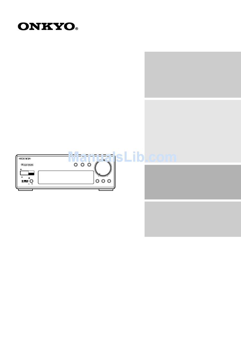
Onkyo ES-600PRO User manual

Artistry
in
Sound
O)\
8
4
ES-600PRO
AV
SURROUND
PROCESSOR

e
Congratulations
on
your
purchase
of
the
ONKYO
ES-600PRO
AV
Surround
Processor.
®@
Please
read
this
manual
thoroughly
before
making
connections
and
turning
power
on.
@
Following
the
instructions
in
this
manual
will
enable
you
to
obtain
opumum
performance
and
listening
enjoyment
from
your
new
ES-600PRO.
®
Please
retain
this
manual
for
future
reference.
CONTENTS
FOE
ATUS
OS
oie
cc
ccc
cc
es
eesecegecceceneeceseesnaeaeeeseuesceeccsesssecuanunestucsecesecsseseecsseusuneerecesteacasecsunessss
bees
ene
suseceeeeaeseteeeseceeeetseeeeeees
IMPOrtant
SAFEQGUAFAS
000...
cece
cccscrecceccneecceusnesescscauenseeceuunyeeteuuseceeeuecscesauseaesauesetsuueesaueseasetsueseuseuuecesueecsraueeeseraess
PFECAUTIONS
2...
iiccccccccsccccccseeeeceeeeeeeeeecseeeaaaaaeeseeesscaeasseeeecaaaeeseceeecaeueasceseeseeaaneeeseesnseasenseesaueeeeecugeceeeaaesaessacesessuseseeccseuusetseseuss
SYSTEM
CONNECTIONS
00.000.
ccceccec
ccc
cnece
ce
cece
cee
eee
ceseecueeeeeeecuvecenscueaesereaeesesceeaesersaeeeseneestaeessesesssnsessssestsacetessayectsanerss
Control
positions
ANd
NAMES
20.0.0...
cece
cece
eseeeeteeeeer
sees
co
vceecu
ee
eecuaeeeueueeeaseetteaseceeeeeuseeeeeeeesenseessesecatetauecenseestaaeeesa
OPEatiOMs
2...
ccc
cece
cece
une
ccc
ceeeccnenesseesececeeseeeeseuauessessecesesccecscecsccecaueuenscstcueeecusaeaveeeececsuteesecuraeseeveceerssanatereereveeenanaes
SUFFOUNd
AAGJUSTEMENTMS
0000...
cecneececcccccecermucvueuseeccneesccceescveanaeeuscuaussceseneeeeeuauesacecesaeuueeeseuavauseeseeeeesuauateteeeeeecesseens
Input
Dalance
ACjJUSTMENTS......
cc
nneentnnneeeceeeeeeeeeeeeeeeeeeeeeenesssaaeseceaensgsesausesseesasecuussaussseecesauerseereeccessceseeees
Section
names
and
functions
(Remote
Control
Transmitter)
........0.00
cece
cceceeeeee
cee
ccc
eeeeneeseeseerseaaaeees
Using
the
remote
Control
transmitter...
ccc
cecceeeccecceseeseceeeaeesecessecueeesseeenaessesesuaaeteeseeseatsausneeeeseeers
REMOTES
CONTFO!
TFANSMITTOT
20.0...
ccecseceesseeeeeseessceeesssseeeesceseeaueeereeessscseeeseuuaecssucuesesunesecsussuesetsauaeeseusauneesessaveness
TrouBbleSNoOoting
Guide...
cccccccccccssceceecceeessepeeseeuse
sess
ceeececeseaeaecesenaasecseeseeaaegeceeeucsceseuesrsanecessraeecesauasesesissaaeeeeeess
SPOCIFICATIONS
0.0...
cccee
ccc
ee ee
cseeeenecceseeeueaeeeseeseceeeseeesenasaususuenssesaeeseceeaeaesesssstecesecuuneayecsecueseccessrssureeevessssauueveressentenees
—_h
“=~
-—-
OO~THAI
AN
PWNHNL
~>
—
eatures
ee
—s——‘(isisisSCSCSSCSCSCSsid
@
Dolby
Pro
Logic
Surround
Sound
System
Dolby
Pro
Logic
Surround
Sound
uses
an
“active
decoder”
configuration
to
produce
a
sonic
composition
remarkably
similar
to
what
you'd
hear
in
a
movie
theater.
Its
“directional
emphasis
circult”
adds
an
tndependently
controlled
“center
channel”
to
the
existing
stereo
L/R
front
channels
and
monaural
L/R
rear
channel.
Not
just
a
combination
of
the
left
and
right
channel
signals,
the
center
channe}!
uses
logic
steering
circuitry
that
increases
separation from
around
3
dB
to
between
26
and
40
dB
for
pinpoint
directionality,
image
stability
and
enhanced
overall
sound
quality.
So
the
voices
of
characters
on
the
screen
always
come
directly
from
the
TV,
never
from
a
side
speaker.
®
Four
Surround
Modes
The
ES-600PRO
gives
the
listener
four
kinds
of
surround
sound
circuitry
to
choose
from
tn
addition
to
Dolby
Pro
Logic:
Dolby
3
Stereo.
Hall
Surround
and
Stadium.
You
can
choose
the
mode
that
best
matches
the
program
material.
®
Adjustable
Digital
Time
Delay
The
ES-600PRO
includes
adjustable
time
delay
for
the
rear
speaker
channels
to
jet
the
user
acoustically
tailor
the
perceived
room
size
to
maich
the
characteristics
of
the
program
materia:.
This
feature
works
with
the
Dolby
Pro
Logic,
Hall
and
Stadium
surround
modes
and
can
be
adjusted
either
manually
or
via
the
remote
control.
Delay
is
adjustable
within
a
range
of
15
-—
30
milliseconds
(5
—
40
mil-
liseconds
In
the
Hall
and
Stadium
surround
modes}.
The
longer
the
delay,
the
larger
the
apparent
acoustical
size
of
the
listening
room.
Three
Built-In
High
Power
Amplifiers
(Center:
50
W,
Rear:
2
x
20
W)
®
Programmable
Universal
Remote
Control
Included
The
remote
control
that
comes
with
the
ES-600PRO0
covers
all
major
surround
processor
functions
and
is
preprogrammed
with
contro!
codes
for
ONKYO
FRI
amplifiers.
cassette
decks
and
CD
players.
In
addition,
it
can
be
programmed
to
“remember”
40
additional!
codes.
That
means
the
user
can
operate
not
only
the
audio
system,
but the
VCR
and
TV
set
as
well
with
a
single
remote.
®
Large
Fluorescent
Display
-AUTION
CEPTACLE
OR
OTHER
OUTLET
UNLESS
THE
BLADES
CAN
BE
“O
REOUCE
THE
RISK
OF
ELECTRIC
SHOCK,
DO
NOT
REMOVE
FULLY
INSERTED
TO
PREVENT
BLADE
EXPOSURE.
OVER
(OR
BACK).
NO
USER-SERVICEABLE
PARTS
INSIDE.
EFER
SERVICING
TO
QUALIFIED
SERVICE
PERSONNEL.”
Oy
porns
®
Sur
ies
modéles
dont
ia
fiche
est
polarisée.
ATTENTION:
pour
prREvENIR
LES
CHOCS
ELECTRIQUES
NE
PAS
UTILISER
CETTE
FICHE
POLARISEE
AVEC
UN
PRO-
LONGATEUR,
UNE
PRISE
DE
COURANT
OU
UNE
AUTRE
SORTIE
DE
COURANT,
SAUF
SI
LES
LAMES
PEUVENT
ETRE
INSEREES
RISK
OF
ELECTRIC
SHOCK
BORE,
(0)
Me)
=]
2,
|
®
The
lightning
flash
with
arrowhead
symbol,
within
A
FOND
SANS
EN
LAISSER
AUCUNE
PARTIE
A
DECOUVERT.
an
equilateral
triangle.
1s
intended
to
alert
the
user
ATTENTION
FOR
BRITISH
MODEL
to
the
presence
of
uninsulated
“dangerous
voltage
@
Replacement
and
mounting
of
an
AC
plug
on
the
power
supply
within
the
product's
enclosure
that
may
be
of
suffi-
cient
magnitude
to
constitute
a
risk
of
electric
shock
cord
of
this
unit
should
be
performed
only
by
qualified
service
to
persons.
personnel.
@
IMPORTANT:
The
wires
in
the
mains
lead
are
coloured
tn
ac-
@
The
exclamation
point
within
an
equilateral
tangle
cordance
with
the
following
code:
is
intended
to
alert
the
user
to
the
presence
of
tm-
Biue:
Neutral
portant
operating
and
maintenance
(servicing)
in-
Brown:
Live
structions
in
the
literature
accompanying
the
appii-
As
the
colours
of
the
wires
in
the
mains
lead
of
this
apparatus
may
ance.
ot
correspond
with
the
coloured
markings
identifying
the
terminals
7
in
your
plug,
proceed
as
foliows:
WARNIN
G
The
wire
which
is
coloured
blue
must
be
connected
to
the
terminai
O
REDUCE
THE
RISK
OF
FIRE
OR
ELECTRIC
SHOCK,
DO
NOT
which
ts
marked
with
the
letter
N
or
coloured
black.
(POSE
THIS
APPLIANCE
TO
RAIN
OR
MOISTURE.”
The
wire
which
is
coloured
brown
must
be
connected
to
the
terminal
For
models
having
power
cords
with
a
polarized
plug.
which
is
marked
with
the
letter
L
or
coloured
red.
AUTION:
TO
PREVENT
ELECTRIC
SHOCK
DO
NOT
USE
@
This
apparatus
complies
with
requirements
of
EC
directive
87
/308/EEC.
11S
(POLARIZED)
PLUG
WITH
AN
EXTENSION
CORD,
RE-
—j-

[mportant
safeguards
ee
BA.
10.
11.
13.
14.
15.
16.
17.
Read
Instructions
~-
Al!
the
safety
and
operating
instructions
should
be
read
before
the
appilance
ts
operated.
Retain
Instructions
-
The
safety
and
operating
instructions
should
be
retained
for
future
reference.
Heed
Warnings
~—
Ail
warnings
on
the
appliance
and
in
the
op-
erating
Instructions
should
be
adhered
to.
Follow
Instructions
~-
Al!
operating
and
use
instructions
should
be
followed.
.
Water
and
Moisture
-
The
appliance
should
not
be
used
near
water
—
for
example,
near
a
bathtub,
washbowl,
kitchen
sink,
ijaundry
tub,
in
a
wet
basement.
or
near
a
swimming
pool,
and
the
like.
.
Carts
and
Stands
-~
The
appliance
should
be
used
only
with
a
cart
or
stand
that
is
recommended
by
the
manufacturer.
An
appliance
and
cart
combination
should
be
moved
with
care.
Quick
stops.
excessive
force,
and
uneven
surfaces
may
cause
the
appliance
and
cart
combination
to
overturn.
PORTABLE
CART
WARNING
Sat
25A
~~
Wall
or
Ceiling
Mounting
to
a
wall
or
ceding
only
as
recommended
by
the
manufacturer.
Tne
appliance
should
be
mounted
.
Ventilation
—
The
appliance
should
be
situated
so
that
its
location
or
position
does
not
interfere
with
its
proper
ventilation.
For
example,
the
appliance
should
not
be
situated
on
a
bed,
sofa,
rug,
or
similar
surface
that
may
biock
the
ventilation
openings;
or
placed
in
a
bulit-in
installation,
such
as
@
bookcase
or
cabinet
that
may
impede
the
flow
of
air
through
the
ventiiation
openings.
Heat
—
The
appliance
shouid
be
situated
away
trom
heat
sources
such
as
radiators,
heat
registers,
stoves,
or
other
appliances
(including
amplifiers}
that
produce
heat.
Power
Sources
-
The
appliance
should
be
connected
to
a
power
supply
only
of
the
type
described
in
the
operating
Instructions
or
as
marked
on
the
appliance.
Polarization
-
If
the
appliance
is
provided
a
polarized
ptug
having
on
blade
wider
than
the
other,
please
read
the
following
information:
The
polarization
of
the
plug
is
a
safety
feature.
The
polarized
plug
will
only
fit
the
outlet
one
way.
If
the
plug
does
not
fit
fully
into
the
outlet,
try
reversing
it.
[f
there
is
still
trouble,
the
user
should
seek
the
services
of
a
qualified
electrician.
Under
no
circumstances
should
the
user
at-
tempt
to
defeat
the
polarization
of
the
plug.
Power-Cord
Protection
--
Power-supply
cords
should
be
routed
so
that
they
are
not
likely
to
be
walked
on
or
pinched
by
ttems
placed
upon
or
against
them,
paying
particular
attention
to
cords
at
plugs.
convenience
receptacles,
and
the
point
where
they
exit
from
the
ap-
pliance.
Cleaning
-
The
appliance
should
be
cleaned
only
as
recommended
by
the
manufacturer.
Nonuse
Periods
~—
The
power
cord
of
the
appliance
should
be
unplugged
from
the
outlet
when
left
unused
for
a
tang
period
of
time.
Object
and
Liquid
Entry
~-
Care
should
be
taken
so
that
objects
do
not
fall
and
liquids
are
not
spilled
tnto
the
enciosure
through
openings.
Damage
Requiring
Service
—
The
appliance
should
be
serviced
by
qualified
service
personnel
when:
A.
The
power-supply
cord
or
the
plug
has
been
damaged;
or
B.
Objects
have
fallen,
or
iquid
has
been
spilled
tnto
the
appliance;
or
C.
The
appliance
has
been
exposed
to
rain:
or
OD.
The
apphance
does
not
appear
te
Gperate
normaliy
or
exhibits
a
markea
change
in
performance;
or
E.
The
appliance
has
been
dropped
or
the
enclosure
damaged
Servicing
-
The
user
should
not
attempt
to
service
the
appliance
beyond
that
described
in
the
operatirg
instructions.
Ali
other
servicing
should
be
referred
to
qualified
service
personnel.
Precautions
a
1.
Warranty
Card
The
serial
number
is
written
on
the
rear
pane!
of
this
unit.
Copy
the
serial
number
and
model
number
onto
your
warranty
card
and
keep
it
in
a
safe
place.
Recording
Copyright
Recording
of
copyrighted
material
for
other
than
personal
use
is
illegal
without
permission
of
the
copyright
hoider.
AC
Fuse
The
fuse
ts
located
inside
the
chassis
and
ts
not
user
serviceable.
lf
power
does
not
come
on,
contact
your
ONKYO
service
center.
Care
From
time
to
time
you
should
wipe
off
the
front
and
rear
paneis
and
the
cabinet
with
a
soft
cloth.
For
heavier
dirt,
dampen
a
soft
cloth
in
a
weak
solution
of
mild
detergent
and
water,
wring
it
out
dry,
and
wipe
off
the
dirt.
Following
this,
dry
immediately
with
a
clean
cioth.
Do
not
use
rough
material,
thinners,
alcohol
or
other
chemical
solvents
or
cloths
since
these
could
damage
the
finish
or
remove
the
panel
lettering.
Power
WARNING
BEFORE
TURNING
ON
POWER
FOR
THE
FIRST
TIME,
READ
THE
FOLLOWING
SECTION
CAREFULLY.
Some
models
are
designed
for
use
only
with
the
power
supply
voltage
of
the
region
where
they
are
sold.
USA
&
Canadian
models:
AC120V,
6OHz
U.K.
&
Australian
models:
AC240V,
50Hz
Worldwide
models:
120
and
220V
switchable,
50/60Hz
®
Voltage
Selector
(Rear
Panel)
Worldwide
models
are
equipped
with
a
voltage
selector
to
conform
with
local
power
supplies.
Be
sure
to
set
this
switch
to
match
the
voltage
of
the
power
supply
in
your
area
before
turning
the
power
switch
on.
Voltage
is
changed
by
sliding
the
groove
in
the
switch
with
a
screwdriver
to
the
right
or
left.
Confirm
that
the
switch
has
been
moved
ai!
the
way
to
the
right
or
left
before
turning
the
power
switch
on.
Models
without
a
voltage
seiector
can
only
be
used
tn
areas
where
the
power
supply
is
the
same
as
that
of
the
unit.
220V
~
120V
~
at
AC120V
220V
~
120V
~
at
AC220V

System
connections
ee
ee
General
USA
&
Canadtan
models
Do
not
plug
in
the
power
cord
until
all
connections
have
been
made.
Atso
be
sure
to
perform
left
and
right
channel
connections
properly.
@
Standard
Connection
Procedures
AC
OMTLETS
Worldwide
models
only
ES-600PRO
\
*
AD
pede
UNSWITE
DT
GA
CK
Nita
\
\
:
ONKYO.
I
n
PE
on
rt
*
(4.
SURROUND
BRS
CE
SSOF
|
~
©
—
7
MODEL
NO
ES-6BO0PRO
-
kK
a
on,
.
RATING
7
Lo
ocon
toon
LO
|
The
|
=
.
“
;
——
.
_
.
_|
ONEYO
CORPORATION
yg
a
f
C
_f
OM.
MAL
thd
—
\
oe
_~
C=
=
Na
_
eS
Nee
——
c
,
:
he.
ae
v
Agco
IMSS
iA?
ane
oe
cae
AC
POWER
SUPPLY
CORD
+
CENTER
SPEAKER
REAR
REAR
AMPLIFIER,
RECEIVER
etc
SPEAKER
SPEAKER
LEFT
RIGHT
@
Yo
connect
the
ES-600PRO
to
a
GRAPHIC
EQUALIZER:
AC
Outlet
(U.S.A.
and
Canadian
models)
®
UNSWITCHED:
This
outlet
is
not
switched
on
and
off
by
the
POWER
switch
on
the
front
panel.
Capacity
is
200
watts.
ES-600PRO
Speaker
Connections
(SPEAKERS)
1.
Connect
the
speakers
to
terminals.
2.
When
connecting
speakers,
proper
polarity
is
important.
Always
connect
the
(+)
terminal
(red)
on
this
equipment
to
the
(+)
terminal
on
the
speaker
and
the
(—)
terminal
(black)
on
this
equipment
to
the
(—)
termina!
on
the
speaker.
3.
Do
not
connect
a
single
speaker
in
parallel
to
the
right
and
left
channei
outputs.
4.
Use
speaker
cables
that
have
a
!ow
impedance
and
that
are
as
short
as
possible.
,
+
Attach
speaker
cables
to
the
rear
panel
speaker
terminals
with
care,
being
sure
that
connections
are
made
firmly
and
that
there
is
no
possibility
of
a
short
circuit
occurring,
Speaker
Cable
Connection
Lift
the
lever
and
insert
the
wire
When
the
wire
has
been
inserted
firmly
into
the
hole,
release
the
lever.
GRAPHIC
EQUALIZER
AMPLIFIER,
RECEIVER
etc.

Control
positions
and
names
Front
panel
For
more
information
about
buttons
or
controls,
turn
to
the
page
number
listed
in
the
[
Display
Remote
Control
Sensor
[8]
Reset
Button
(RESET)
[6]
}.
Volume
Control
Knob
(VOLUME)
[5]
input
Balance
Control
Knob
(INPUT
BALANCE)
[6]
POWER
Switch
Delay
Time
Buttons
(DELAY
TIME)
[6]
Center
Level
Control
Buttons
(CENTER
LEVEL)
[6]
Rear
Level
Contro!
Buttons
(REAR
LEVEL)
[6]
HALL,
STADIUM)
Display
CENTER
MODE
indicator
Center
off
Button
(CENTER
OFF}
[6]
Center
Mode
Button
(CENTER
MODE)
[5]
By
Pass
Button
(BY-PASS)
[5]
Surround
and
3
Stereo
Mode
Buttons
[5]
(DOLBY
PRO
LOGIC,
DOLBY
3
STEREO,
Surround
Mode
indicator
MUTING
indicator
fe
.
~
ae
a
.
/
;
SURROUND
MODE
|(MOODE]\
[
CENTER
MODE
|
MUTING
CENTER
REAR
[
ee
l
a
LEVEL LEVEL
\
|
DOLBY
|
?
©
See
6
.
eee
™
ee
_7
_—_——
s
'———
¢
1.
Dees
5
°°
eee
+
Parameter
indicator
REAR
LEVEL
indicator
CENTER
LEVEL
indicator

Operations
ee
a
a
ee
ee
@
This
model
is
equipped
with
four
different
surround
modes.
which
are
selected
using
the
Surrourd
and
3
Stereo
Made
buttons.
Select
the
modes
according
to
the
type
of
program
being
played
and
the
desired
ambience,
such
as
that
of
a
movie
theater.
a
concert
hail.
etc
®
This
model
includes
a
built-in
Dolby
Pro
Logic
Surround
decoder.
Dalby
Pro
Logic
Surround
was
developed
as
a
consumer
version
of
the
Dolby
Stereo
system
used
in
movie
theaters.
It
is
suitable
for
plaving
sources
recorded
with
the
Dolby
Surround
system.
ONwHWCI
ae
Press
once
to
turn
power
on
and
once
again
to
turn
power
off.
_
@
The
display
is
illuminated
when
power
!s
on
2
Turn
on
the
amplifier
which
is
connected
to
this
model.
then
select
the
desired
input
source.
"3:
Select
the
desired
mode
with
the
Surround
or
3
Stereo
Mode
buUtTONS.,
This
mode
|s
appropriate
for
piaying
program
materia!
that
was
recorded
using
Dolby
Surround
fhe
same
thril!
felt
when
viewing
4
program
in
a
movie
theater
can
be
enjoyed
when
this
mode
!s
selected
@
Commercial
video
sources
recorded
with
the
Dolby
Surround
system
are
‘ndicated
by
the
DU:
cever
SURROUND
Mark
Surround
Adjustments
a
Select
the
destred
mode
with
the
Surround
or
3
Stereo
Mode
buttons.
Pro
Logic
Modes
Piped
Fett
Fea
ot
Pa
OS
I
ELSE
ALLS
AAGT.,
Sei
to
this
mode
for
normal
Pro
Logic
playback,
Tebdd
Cet
ne
ee
ee
a
a
@
ott
fr
7
Lt
;
When
not
using
rear
speakers,
set
to
this
mode.
2)
Pressing
the
CENTER
MODE
button
shifts
the
center
mode
in
the
sequence
:ndicated.
THR
rh
@
fii;
LE
Bek
ie
ipa
ein
Where
rear
speakers
are
not
available,
DOLBY
3
STEREO
provides
partial
reproductton
of
the
Dolby
Pro
Logic
Sur.
round
capabilities
using
only
the
3
front
channeis
tieft,
righ’
and
center).
For
only
the
3
front
channels,
the
directionality
enhancer
circuit
allows
the
shifting
sound
feature
of
Dolby
Pro
Logic
Surround
to
be
enjoyed.
The
surround
signal
is
reproduced
at
an
appropriate
distance
between
the
front
left
and
nght
speakers
Use
of
the
rear
speaker
system
is
recommended
for
full
en.
joyment
of
Dolby
Pro
Logic
Surround
e
/
if
.
ie
This
mode
is
suitable
for
classical
and
other
types
of
music
characterized
by
its
many
sound
reverberations
f
!
Prt
ad
d
itta
e
!
f
“ioe
VP
gE
SE
titi
|
Actual
movie
theaters
use
many
rear
speakers.
These
modes
dare
designed
io
replicate
this
atmosphere
They
are
suitable
for
playing
program
materiai
that
was
recarded
using
Dolby
Surround
FAG
29
EAL
LES
Pe
.
ee
aes
pal
ay
ee
The
surround
mode
1's
not
used
Audio
input
signals
(ieft
and
right)
are
conveyed
directly
to
the
front
speakers
without
sound
modification.
4
Start
piay
of
the
selected
input
source.
5
Adjust
the
Volume
Cortrai
knob
of
this
model
or
the
amplifier
which
is
connected
to
the
appropriate
level
Center
Modes
Dalby
Pro
Logic
Surround
requies
a
center
speaker
tor
reproducing
the
center
signal.
The
mode
shoutd
be
selected
based
on
the
tyne
of
center
speaker
used.
ef
a
oe
a
The
center
speaker
1s
Smaiier
or
otherwise
less
able
than
the
front
speakers
to
handle
bass
frequencies.
The
center
signa!
is
divided
so
that
sounds
above
100
Hz
are
reproduced
by
the
center
speaker
and
those
below
are
applied
to
the
front
speakers
iid
GE
IP]
in
this
case.
the
bass
response
of
the
center
speaker
system
is
essentially
equal
to
that
of
the
fromt
speakers.
The
center
channei
sound
ts
completely
applied
to
the
center
speaker
e
|
hf
|
Ni
a
a
‘i
Select
this
mode
if
a
center
speaker
is
not
used
The
center
channel
sound
is
appliec
to
the
front
speakers

3
Press
the
DELAY
TIME
(-.
~)
button
ne
i
i
fEoe'd
i.
i
|-~
With
certain
programs,
sounds
that
should
be
heard
from
the
rear
emerge
from
the
center,
or
vice
versa.
in
such
cases,
the
delay
time
can
be
adjusted
for
the
correct
sound
positioning.
The
standard
setting
ig
20ms.
but
if
correction
is
needed,
select
fram
among
15.
20
25
and
3Gms.
However,
to
optimize
the
surround
effect,
determine
the
setting
from
the
relationship
in-
dicated
in
the
figure.
The
delay
time
carinot
be
set
during
DOLBY
3
STEREO.
Delay
time
LAS:
4
L1
Distance
from
center
speaker
to
listening
position
L2
Distances
from
rear
speaker
fo
hsteniag
Dasitien
NOTE:
-
The
delay
time
changes
from
5
ms
to
40
ms,
if
Hall
or
Stadium
mode
ts
selected
Input
Balance
Adjustment
eae
eee
During
DOLBY
PRO
LGGIC
SURROUND
playback.
if
conversation
which
should
be
heard
directiy
from
the
center
Is
off
to
either
the
eft
or
ght.
the
INPUT
BALANCE
Controi
Knob
can
be
used
to
adtust
the
balance
as
totiows.
INR
WED
+
f
|
..
1
a
3
“
=~)
\
4
ri
H
i
;
:
..
|
i
i
1
s
4
|
i
|
Press
either
the
DOLBY
PRO
LOGIC
Button
or
the
DOLBY
3
STEREO
Buttan
.
@
The
Input
Ba:ance
is
in
operation
whie
the
DOLBY
PRO
LOGIC
and
DOLBY
3
STEREO
Surround
modes
are
in
effec!
2
Play
back
Go
Source
from
which
the
conversation
can
be
heard
trectiv
from
the
front
3
Press
the
CENTER
OFF
Buiton
on
tne
unit
@
The
sound
from
the
center
speaker
wii
ro
tanger
be
heard.
4
usingthe
INPUT
BALANCE
Contre:
Knob.
adjust
until
the
sound
of
the
vaice
reaches
its
m-nimum
level
5
Press
the
CENTER
OFF
Button
of
the
une
®@
Tee
scunrd
tram
we
certer
speaker
wit
be
audible
again
Ths
COMmp
ates
the:
adusimenm
4)
Press
the
TEST
button
on
the
remote
control
transmitter.
The
best
effect
is
obtained
from
the
Dolby
Pro
Logic
Surround
when
the
volume
is
balanced
among
the
speakers.
~~]
rt
TE?
Pope
ft
¢
)
~
@
Set
it
to
a
low
position
in
order
to
avoid
a
sudden
occurance
of
high
volume
when
beginning
operations
with
the
test
tone.
@
When
the
remote
contro!
TEST
button
is
pressed,
the
tone
emanates
from
the
speakers
in
the
sequence
Front
Left
(L)
Center
(C)
—
Front
Right
(R)
—
Rear
(S)....
From
the
listening
position.
use
the
CENTER
and
REAR
LEVEL
buttons
to
adjust
for
equal
test
tone
volume
on
each
channel,
@
inthe
PHANTOM
center
mode
the
test
tone
alternates
be
tween
the
front
(left
and
right}
and
rear
channels.
5
Pressing
the
TEST
button
again
will
turn
off
the
test
tone
@®
The
test
tone
continues
far
1.5
seconds
on
each
channel
for
a
total
speaker
system
check
time
of
90
seconds.
When
tne
RESET
Button
is
pressed.
the
values
set
for
DELAY
TIME,
CENTER
LEVEL.
and
REAR
LEVEL
when
making
the
surround
adjustments
are
returned
to
their
;
initial
values
|
NOTE:
When
using
HALL.
STADIUM
or
BY-PASS.
set
the
INPUT
BALANCE
Contre!
Knob
to
the
center
position.

Section
Names
and
Functions
(Remote
Control
Transmitter)
Remote
Control
Transmitter
(RC-199M)
The
following
buttons
are
used
to
controi
the
ES-600PRO
@)
Operation
Indicators
The
two
indicators
function
as
guides
when
codes
are
stored
in
the
remote
control
transmitier.
If
the
encoding
process
is
incomplete
or
the
battery
depleted
the
LEARNED/SENDING
indicator
will
flash
whenever
a
button
is
pressed.
LEARN/A/B
Switch
A:
Set
to
this
position
during
operatian
for
(3)
—
ay
buttons
and
other
white
characters.
B:
tn
this
position,
al!
buttons
are
operable
except
(3)
through
)
.
LEARN:
Use
this
position
to
input
the
code
of
another
remote
control
transmitter.
Test
Tone
(TEST)
Test
tone
on/off.
Surround
Mode
(SURROUND
MODE)
Surround
mode
selector
button.
Operation
is
the
same
as
that
of
the
surround
mode
button
of
the
front
panel.
Surround
Mode
On/Off
Button
(ON/OFF)
OFF:
Operation
is
the
same
as
that
of
the
BY.PASS
button
of
the
front
panel.
ON:
The
status
prior
to
turning
the
mode
off
is
resumed.
Center
Speaker
On/Off
Button
(CENTER
ON/OFF)
Turns
the
Center
Speaker
on
and
off
when
adjusting
the
input
balance.
Center
Level
(CENTER
LEVEL
a
/
WW)
Adjust
the
center
speaker
volume.
4
:
Increases
the
volume
vw
:
Decreases
the
volume
Rear
Level
(REAR
LEVEL
a/
VW
)}
Adjust
the
rear
speaker
volume.
&
:
Increases
the
volume
vw
©
Decreases
the
volume
Delay
Time
(DELAY
TIME)
Use
this
button
to
select
the
delay
time.
Muting
Button
(AUDIO
MUTING)
Press
to
activate
muting
and
cut
off
the
sound.
Press
again
to
deactivate
the
muting
and
return
to
original
volume
level.
Switching
off
power
to
the
unit
also
deactivates
the
muting.
Volume
Control
(VOLUME
4
/
Ww
)
Adjust
volume
level
A
|
increases
the
volume
v
:
Decreases
the
volume

Using
the
remote
control
transmitter
aaa
@®
For
details
on
the
function
of
each
control,
see
the
description
in
“Remote
Control
Transmitter”
(RC-199M)
on
page
7.
®
Batteries
The
remote
control
transmitter
is
powered
by
two
batteries.
Before
using
this
unit
for
the
first
time,
insert
the
two
batteries
(included)
as
shown
in
the
diagram
The
remote
contro!
trans-
mitter
has
no
on/otf
switch.
Average
battery
life
is
one
year.
This
period
may
be
shorter
depending
on
the
frequency
of
use
and
environment
(temperature
and
humidity)
in
which
the
re-
mote
control
transmitter
is
used.
If
the
remote
contro!
transmitter
does
not
operate
even
though
front
panel
controls
function
normally,
the
batteries
should
be
replaced.
Use
only
batteries
listed
in
the
following
chart.
AA
1.5V
R6
Manga-
nese
Do
not
leave
an
exptred
battery
in
the
case
as
it
may
leak
or
damage
the
battery
case.
When
inserting
the
batteries.
be
sure
the
(+)
and
(-)}
ends
are
properly
aligned.
Do
not
use
nickel-cadmium
(rechargeable)
batteries.
Do
not
use
one
specified
(manganese)
battery
and
one
al!-
kaline
battery
at
the
same
time.
Replace
both
batteries
at
once;
do
not
use
one
old
and
one
new
battery
together.
Transmitter
Battery
Replacement
ES-600PRO
Remote
sensor
a
approx.
Sm
j
LS
(16
feet)
Remote
controt
transmitter
RC-199M
Precautions
Remove
the
batteries
if
the
remote
control
transmitter
is
not
going
to
be
used
for
a
jong
time.
The
batteries
of
the
remote
control
transmitter
must
be
replaced
periodically.
Remember,
however,
that
commands
will
be
re-
ceived
only
when
the
main
power
switch
of
the
ES-600PRO
Is
On.
This
unit
uses
infrared
rays.
Therefore.
commands
may
not
be
received
properly
!f
the
front
panel
of
the
ES-600PRO
ts
exposed
to
bright
light.
To
prevent
this
from
occurring,
place
the
ES-600PRO
so
that
it
Is
not
directly
exposed
to
a
bright
light.
If
the
ES-600PRO
is
piaced
tnside
an
audio
rack
behind
a
glass
door,
the
door
should
not
use
colored
glass
or
have
any
deco-
rations
on
!t
since
this
could
shorten
the
range
or
prevent
commands
from
being
received.
Use
of
other
infrared
remote
control
devices
in
the
same
room
may
cause
Interference.
(He
rravisnitter
operates
Uo
to
@a
Wstatice
Of
about
ve
rrerers
(16
feet}.
The
transmitting
window
must
always
be
pointed
at
the
reception
window
when
a
command
is
sent
to
the
ES-600PRO.
If
this
remote
contral
transmitter
does
not
operate
properly,
confirm
that
the
batteries
are
not
dead.
If
the
problem
persists,
contact
your
ONKYO
service
center.

Remote
Control
Transmitter
ee
NOTES:
@®
Commands
of
systems
with
the
ONKYO
FRI
mark
are
already
stored
at
the
A
position
and
part
of
the
B
section
of
the
LEARN/A,’B
selector
switch
There
is
no
need
to
“learn”
them.
{The
FRI
mark
is
ONKYQO’s
own
mark).
If
necessary,
the
buttons
in
the
following
figure
marked
with
number
3
can
be
placed
in
the
memory
with
a
different
code.
Blue
characters
are
used
to
input
codes
into
the
memory.
Set
a
code
on
your
existing
remote
control
to
an
appropriate
blue
character.
When
using
the
memory
the
LEARN/A/B
switch
must
be
on
A.
The
output
of
most
infrared
remote
contro!
transmission
units
on
the
market
today
consists
of
a
series
of
pulses
(codes).
By
changing
these
codes.
functions
can
be
differentiated
between
products
of
different
manufacturers.
In
order
to
operate
certain
functions,
the
codes
of
that
particular
unit
have
to
be
assigned
the
same
code
for
the
function
to
work
correctly.
|
J
1
YH
i
|
ONKYO
731
“UNIFIER
LN
CQ)
Display
Indicators
(PRESS
MATCHING
KEYS,
LEARNED/SENDING)
These
indicators
act
as
guides
when
this
unit
“learns”
and
“uses”
commands.
They
aiso
warn
the
user
when
an
error
Is
made
or
when
battery
power
Is
low.
|
(2)
Learn/A/B
Selector
Switch
(LEARN/A/B)
Set
this
switch
to
A
or
B
when
operating.
Set
the
switch
to
LEARN
for
memorizing
other
remote
control
codes.
(3)
These
buttons
are
for
operating
other
ONKYO
products
that
have
the
FRI
mark
(white
characters).
They
can
be
operated
at
either
A
or
B
settings
of
the
LEARN/A/8
switch
(white
characters)
These
buttons
are
capable
of
learning.
@
Operate
Deck-B.
if
a
single
deck
is
used.
(4)
These
buttons
are
for
operating
this
model.
They
can
be
operated
with
the
LEARN/A/B
switch
set
to
A.
For
a
detailed
description,
see
page
5.
®
The
Audio
Muting
button
and
Volume
button
can
operate
the
ES-600PRO
in
the
A
position,
and
these
buttons
can
also
be
used
for
operating
other
equipment
when
in
the
B
position.
How
to
Learn
(Applicable
anty
to
A
side)
1)
Set
the
LEARN/A/B
selector
switch
to
LEARN.
Qo
Place
the
head
of
your
existing
remote
control
unit
2
--
4
inches
(5
-—
10
cm)
from
the
head
of
this
unit,
laying
both
units
on
a
table
or
another
flat
surface.
“3:
Press
the
button
of
this
unit
into
which
you
want
to
memorize
the
cade.
The
“PRESS
MATCHING
KEYS"
indicator
lights.
4)
Hold
down
the
button
you
want
to
memorize
on
your
existing
remote
contro!
unit
while
the
“PRESS
MATCHING
KEYS"
tn-
dicator
is
lighted
until
the
LEARNED/SENDING
indicator
iights.
5
To
continue
the
process
and
memorize
another
key,
repeat
steps
35-4).
Buttons
corresponding
ta
3
i@g.
power)
3)
+
—$_______»
5.
10cm
i2
-
4
inches)
ONKBRYO
Head
of
your
existing
remote
control
unit
Head
of
this
unit
(RC-199M)}
NOTES:
@®
Someremote
controllers
use
a
single
button
to
change
codes,
with
the
code
changing
each
time
the
button
is
pressed.
If
you
are
using
this
kind
of
controller,
please
perform
“learn”
functions
for
each
of
the
buttons
individually,
one
function
to
one
RC-199M
button.
This
remote
control
transmitter
uses
tnfrared
rays.
Most
remote
control
codes
can
be
memorized
using
the
in-
frared
system:
however,
depending
on
the
degree
to
which
the
system
differs,
there
are
some
rare
occasions
where
memorization
is
not
possible.
Be
sure
to
assign
functions
to
the
buttons
with
the
corre-
sponding
function
names
and/or
symbols.
if
functions
and
button
names
are
different,
the
function
which
actually
op-
erates
will
be
different
from
that
which
ts
displayed.
For
instructions
regarding
the
operation
of
“learned”
units,
please
refer
to
the
individua!
instruction
manuais
for
each
product.
Even
after
codes
have
been
memorized,
piease
keep
your
existing
remote
contro!
transmitter
in
a
safe
place.
If
the
memorized
codes
are
lost
when
the
batteries
run
down,
etc.,
it
will
be
necessary
to
memerize
them
once
again using
the
existing
remote
controi
transmitter.

Operation
DY
LEARN-A’B
selector
switch
to
Aor
B
-
a a
|
Pty
a
V)
Set
the
LEARN/A/B
selector
switch
to
either
A
or
B.
Then
op-
erate
the
remote
contro!
transmitter
by
pressing
the
buttons
of
tne
functions
you
wart
to
use
®
There
is
no
power
switch
ar
the
remote
cantrol
transmitter
Power's
supplied
automatically
when
a
button
1s
pressed.
If
no
button
is
pressed
for
a
short
interval,
power
goes
off
automatically.
to
avoid
wast
nq
the
battery.
®
if
you
press
a
button
at
which
no
code
has
been
memorized.
the
“LEARNED.
SENDING’
indicator
will
not
ight
up
NOTE:
Piease
check
whether
previousiy
memorized
functions
are
working
properly.
The
sending
indicator
may
not
be
:/uminated
with
your
existing
remote
control
unit
Changing
Commands
1
LEARN
4&
4
selector
switch
tae
|b
ARN
a
aoe
ere
+
_)
ee
oo
JJ
J
Pb
L
‘TL
Set
the
LEARN’A
B
selector
switch
to
LEARN.
2
Commands
should
be
memor
zed
using
the
system
outlined
in
the
section,
“How
to
Learr
’
New
codes
of
newly
entered
buttons
only
are
modified.
and
the
codes
of
previously
memo
nized
buttons
are
rat
maditied.
Manufactured
under
license
from
Dolby
Laboratories
Licensing
Corporation.
Additionally
licensed
under
one
or
more
of
the
following
patents:
US.
numbers
3,632,886.
3,746,792
and
3,959,590;
Canadian
numbers
1.004.603
and
1.037
877.
“Dolby”
and
the
double-D
symbo!
are
trademarks
of
Dolby
Laboratories
Licensing
Corporation.
How
to
Reset
the
RC-199M
(Clearing
All
Memorized
Commands)
+
a
LEARN.A’RB
selector
switch
to
LEARN
a
J
j
1
I
i
(2)
POWER
and
AUDIO
MUTING
!
a
|
1)
Set
the
LEARN/A’B
selector
switch
to
LEARN.
.2)
Hold
down
both
the
POWER
button
and
the
AUDIO
MUTING
at
the
same
time.
Continue
holding
these
buttons
down
unti!
the
PRESS
MATCHING
indicator
and
LEARNED/SENDING
indicator
light
up
and
are
then
turned
off.
@
When
the
indicators
are
turned
off,
the
reset
operation
's
completed.
@®
When
the
A
section
is
reset.
the
preset
ONKYO
codes
will
be
recalled.
If
the
Indicators
Flash
1.
During
learning,
the
indicators
flash
when
the
same
codes
are
stable
and
cannot
be
memor:zed
multiple
times.
To
ensure
the
reception
of
stabie
codes,
piace
both
remote
control
units
on
a
table
or
other
level
surface
and
position
them
at
a
fixed
distance
and
orientation.
The
indicators
may
flash
in
case
an
audio
device
can
be
con-
trolled
by
the
existing
remote
control!
unit
but
the
cades
cannat
be
memorized
by
the
RC-199M
This
is
because
the
RC
199M
requires
highly
stable
transmission
output
for
identifying
codes.
Replace
the
batteries
of
the
existing
remote
contro!
unit
with
new
ones,
then
repeat
the
learning
operation
3.
If
the
:ndicators
flash
when
a
button
1s
pressed,
it
means
that
the
RC
199M
batteries
are
worn
out
Replace
its
batteries
with
new
ones
Ao
lO
-

Trouble
shooting
guide
ee
@
If
this
model
appears
to
be
malfunctioning.
Make
sure
the
connecting
cables
and
the
speaker
cables
are
connected
correctly.
See
page
3,
“System
Connections”.
Power
on
but
no
sound
Center
speaker
sound
is
absent
or
weak.
Rear
speaker
sound
is
absent
or
weak.
The
test
tone
does
not
work.
®
AUDIO
MUTING
switch
on.
®
Switch
to
off
by
remote
control
transmitter.
@
The
VOLUME
control
may
be
set
to
“O".
|
@
Adjust
for
an
optimum
sound
level.
@
Surround
mode
set
for
BY-PASS.
@
Set
for
the
surround
mode.
@
Center
jevel
is
at
minimum.
@
Adjust
for
suitable
center
level.
@
Center
mode
set
for
PHANTOM.
@
Set
center
mode
for
NORMAL
or
WIDEBAND.
@®
CENTER
OFF
button
on.
@
Surround
mode
set
for
BY-PASS.
®
Set
for
the
surround
mode.
®
Button
to
oft.
@
Rear
level
is
set
to
Minimum.
®
Adjust
for
suitable
rear
level.
®
Pro
Logic
mode
set
for
DOLBY
3
@
Set
for
DOLBY
PRO
LOGIC,
HALL,
STADIUM
STEREO.
mode.
@
The
surround
mode
is
not
set
on
@
Set
the
surround
mode
on
DOLBY
PRO
LOGIC,
DOLBY
PRO
LOGIC,
DOLBY
3
DOLBY
3
STEREO
STEREO.
Specifications
ee
Power
Output:
Total
Harmonic
Dist.:
IM
Distortion:
Damping
Factor:
Output
(LINE):
Sensitivity
and
|mp.:
Frequency
Response:
Delay
Time:
Signal
to
Noise
Ratio:
MUTING:
Power
Supply
Rating:
SN
29341632
50
watts
per
channel!
min.
RMS.
at
8
ohms,
from
20Hz
to
20,000Hz
with
no
more
than
0.09%
total
harmonic
distortion
(CENTER
)
20
watts
per
channel
min.
RMS.
into
8
ohms,
1000Hz
with
no
more
than
1%
total
harmonic
distortion.
(REAR)
0.09%
at
rated
power
(CENTER)
0.09%
at
1
watts
output
(CENTER)
0.09%
at
rated
power
(CENTER)
0.09%
at
1
watts
output
(CENTER)
50
at
8
ohms
(CENTER)
150mV
(volume
max.)
Dolby
Pro
Logic:
200mV,
50kohms
Hall:
200mV,
50kohms
Stadium:
200mV,
50kohms
20
to
20,000Hz,
+/~-
1dB
(CENTER)
40
to
7,000Hz,
+OdB,
-—3dB
(REAR)
15
to
30ms
(5ms
step)
(Dolby
Pro
Logic
Surround)
5
to
40ms
(5ms
step)
(Hall/Stadium
Surround)
80dB
(IHF-A,
Shorted)
(CENTER)
-60dB
USA
&
Canadian
models:
AC120V
60Hz
U.K.
&
Australian
models:
AC240V
50Hz
Worldwide
Models:
120
and
220V
50/60Hz
switchabie.
Dimensions
(Wx
H
x
D):
455
x
90
x
320
mm
17-15/16"
x
3-9/16"
«x
12-5/8"
Weight:
6.
3kg
13.9lbs.
Specifications
and
features
are
subject
to
change
without
notice.
ONKYO
CORPORATION
International
Division:
Onarimon
Yusen
Bidg.,
23-5,
Nishi-Shimbashi
3-chome,
Minato-ku,
TOKYO
105,
JAPAN
Tel:
03-3432-6987
Fax:
03-3436-6979
ONKYO
U.S.A
CORPORATION
200
Williams
Drive,
Ramsey,
N.J.
07446,
U.S.A.
Tel:
201-825-7950
Fax:
201-825-8150
O1-13-1K-ASA
Printed
in
Japan
E]
Other manuals for ES-600PRO
2
Other Onkyo Computer Hardware manuals