Amp Diag Mode after Abnormal Conditions
543
2
1 6
D
C
A
B
D
C
A
B
543
2
1 6
COMMON
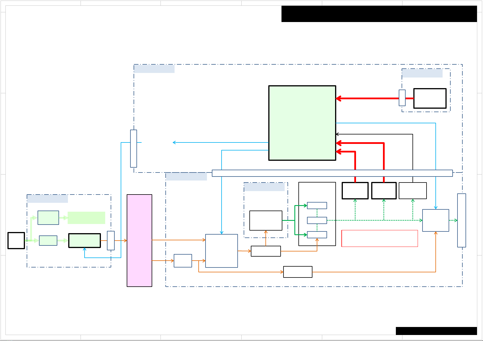
Self-diagnostics
This function is for avoiding the rupture of electrolytic capacitors with amplifier circuit
failure during power-ON.
Operation of Self-diagnostic
Self-diagnostic will start at the timing of next power on, after goes to the protect mode
by Current detection or DC voltage detection.
Only On/Standby key could work in this mode. Also remote control does not work.
However, the CLEAR operation is enabled.
During Self-diagnostic, the power supply for amplifier circuit become low voltage
state(SEC1-LOW), and the speaker relay will be turned off. Then, MPU will check each
amplifier circuits Internally by entering the test signal (20 kHz,-20 dBFS sine wave) to
each channel from DSP.
MPU will judge the amplifier circuit is good or not from VOLH value.
The normal range of VOLH value is 0.04 V < VOLH < 0.20 V.
If VOLH value is in the out of this range, it will be judged as NG (No good).
No problem found
When protected by current detection, and no problem found, "CHECK SP WIRE“ will be displayed.
In this State, Only the On/Standby key is effective. And if do not anything for 3 minutes, unit goes
into standby automatically.
When protected by a DC voltage detection, and no problem found, unit goes into normal
operation.
Problem found
When judged as there is a problem on any channel, the information of channel that has a problem
will be displayed as in the right figure.
In this State, Only the On/Standby key is effective. Also remote control does not work. If do not
anything for 3 minutes, unit goes into standby automatically. This state will keep also after unit
turn on/off, or AC unplugged.
the power supply for amplifier circuit become low voltage state(SEC1-LOW), and the speaker
relay will be turned off.
Display of during Self-diagnostics
A M P D i a g M o d e
2 Line FL tube type
“Mode” This part display the channel which is currently checked. (E.g. "[FL]", etc.)
A M P D i a g M o d e
1 Line FL tube type
Display of when problem found
N G C H :
L C R S L S R B L B
R
N G : L C R S L S R B L B R
2 Line FL tube type
1 Line FL tube type
L
C
R
S L
S R
B L
B R
Front L channel
Center channel
Front R channel
Surround L channel
Surround R channel
Surround back R channel
Surround back L channel