RXW Leaf Wetness Sensor (RXW-LWA-xxx) Manual
1-800-LOGGERS 5 www.onsetcomp.com
2. Use two cable ties to secure the sensor to the bracket. Do
not fully tighten the cable ties.
3. Note that one side of the sensor surface has a visible grid.
The grid side should be facing upwards. Typically the sensor
is mounted at an angle of 15 to 45 degrees from horizontal.
4. Once the desired angle has been set, pull the cable ties tight
and cut off the tag ends.
5. Secure the sensor cable with cable ties.
Sensor Operation
The leaf wetness sensor measures the percentage of the sensor
grid that is wet. A completely dry sensor will record 0%
wetness, while a measurement of 100% wetness corresponds
to the sensor being completely covered with a thin layer of
water.
After prolonged exposure to very hot and wet environments,
the sensor may return to only 1 to 3% wet when dried out, but
given a day or two in a warm, dry environment, the sensor will
recover and return to zero when dry.
IMPORTANT: Do Not Paint the Sensor.
Unlike most other leaf wetness sensors, the leaf wetness sensor
is ready to use and should not be coated. Some manufacturers
of leaf wetness sensors recommend painting their sensors with
a flat latex paint to improve the sensor’s characteristics. These
manufacturers supply their sensors uncoated and require the
user to paint it.
Do not coat the HOBO leaf wetness smart sensor. Onset’s
sensor is preconditioned and factory calibrated. Although it is
certainly possible to alter the response of the sensor by
painting it, applying any sort of coating will only reduce its
sensitivity.
Calibration
The leaf wetness sensor should be field calibrated to determine
the wet/dry transition point. Various types of vegetation will
have varying transition points. The best practice is to install a
station and the leaf wetness sensor in the study area and, while
logging data, directly observe the plants to record the time of
day that the vegetation makes the transition from wet to dry.
Export the logged station data to determine the percent
wetness when the wet/dry transition was observed. In most
cases, this is the value that will best represent the wet/dry
transition point for your study. You will need to retain this
value for use with any third-party software.
Maintenance
The sensor is a capacitive sensor and is less sensitive to
contamination than resistive sensors. However, dust, dirt or
other contaminants on the sensor will retain moisture and that
will ultimately affect the sensor’s performance. You should
periodically inspect the sensor and gently clean the sensor grid
once per year with a non-abrasive rag, mild soap, and fresh
water.
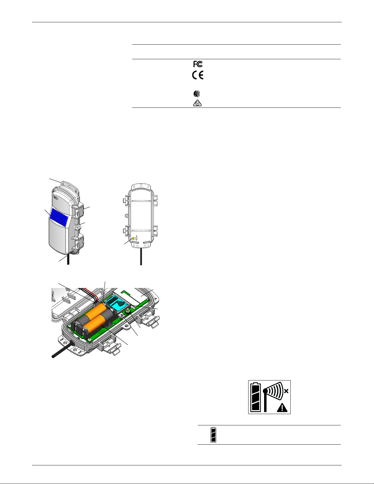
The mote is designed for outdoor use, but should be inspected
periodically. When inspecting the mote, do the following:
•Verify the mote is free of visible damage or cracks.
•Make sure the mote is clean. Wipe off any dust or grime
with a damp cloth.
•Wipe off any water before opening the mote.
•Make sure the interior seal is intact and the latches are
fully locked when the mote door is closed.
Verifying Sensor Accuracy
It is recommended that you check the accuracy of the leaf
wetness sensor annually. If the sensor is not providing accurate
data, it may be damaged or broken.
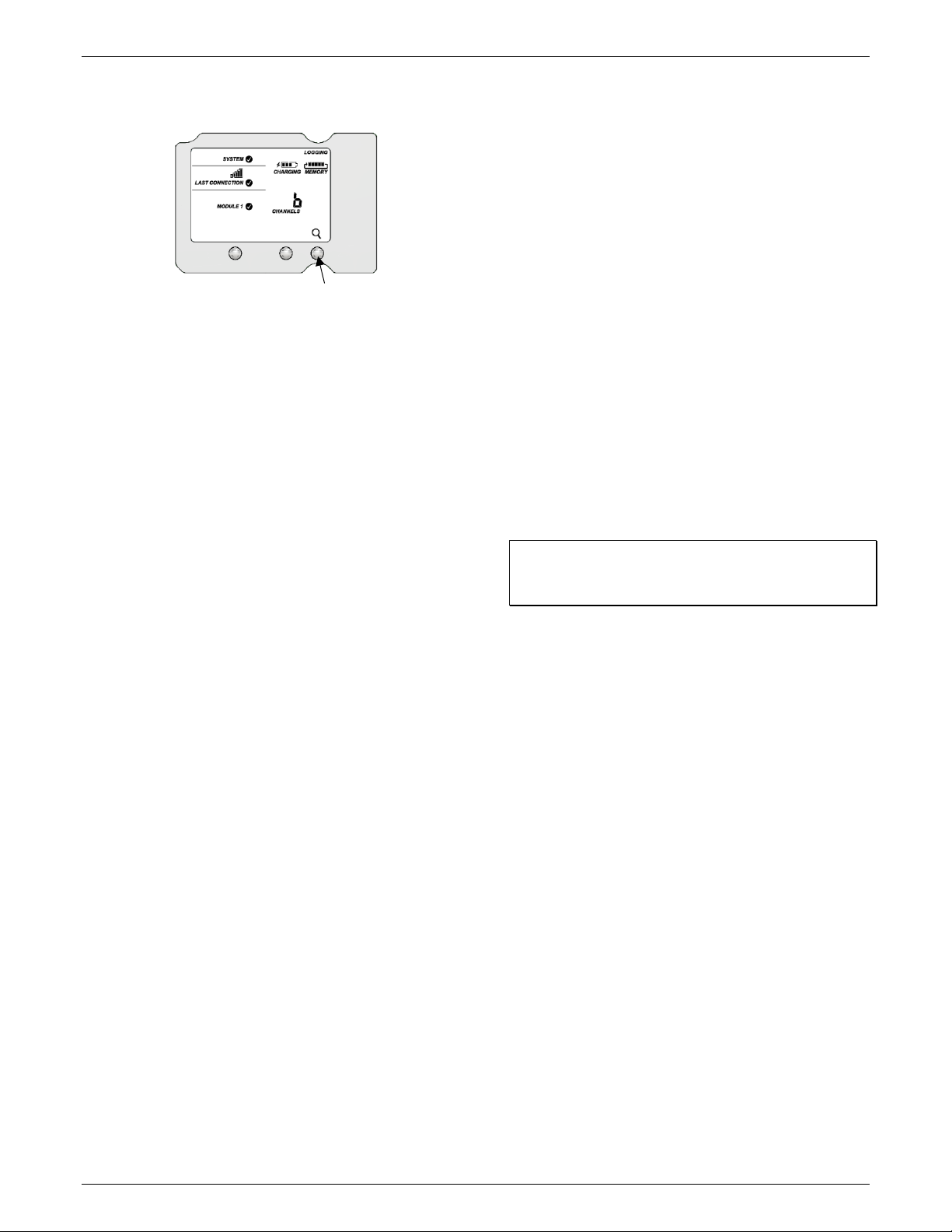
Updating Mote Firmware
If a new firmware version is available for the mote, use
HOBOlink to download the file to your computer.
1. In HOBOlink, go to Devices, RX Devices, and click your
station name.
2. On the station page, click Overview and scroll down to
Device Information.
3. Click the Wireless tab. This icon appears next to the
mote if there is a new version of firmware available.
4. Click the firmware upgrade link. Click Download and
save the firmware .bin file to your computer.
5. Connect the mote to the computer with a USB cable (open
the mote door and use the USB port to the right of the
LCD). The blue LED is illuminated while connected.
6. The mote appears as a new storage device in the
computer’s file storage manager. Copy the downloaded
firmware file to the new storage device (the mote). The
blue LED will blink slowly while the file is copying.
7. After the file is copied to the mote, the LED will stop
blinking and remain a steady blue. Eject the storage device
from the computer and disconnect the cable from the
mote. The firmware installation process will begin
automatically on the mote. The blue LED will blink rapidly
while the firmware is installed. Once the firmware
installation is complete, the LCD symbols return and the
mote will automatically rejoin the network.
Notes:
•Mac® users: A message may appear indicating the disk
has not ejected properly when disconnecting the mote
from the computer. The mote is operational and you can
ignore the message.
•If the blue LED turns off abruptly while copying the file or
installing the firmware, a problem has occurred. Contact
Onset Technical Support for help.
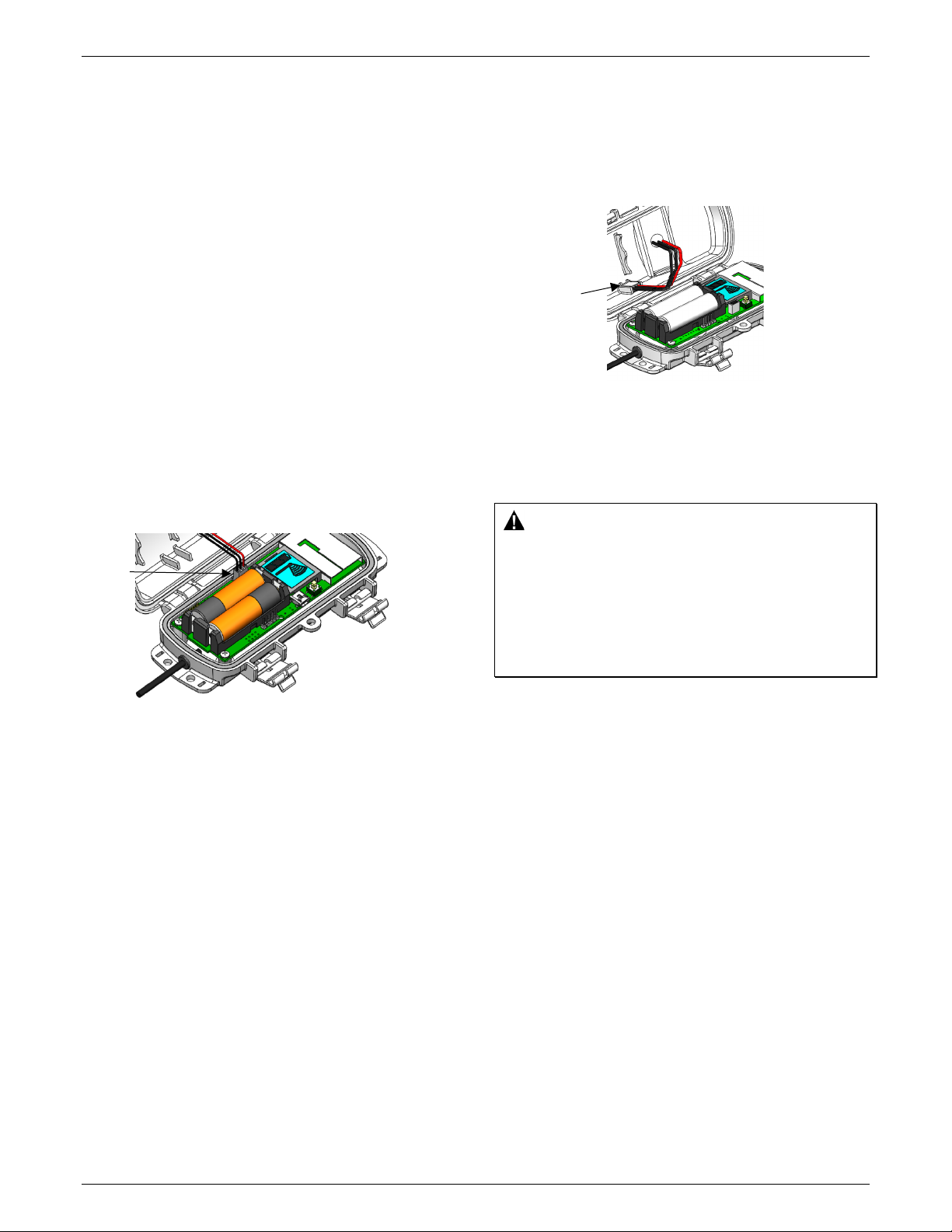
Battery Information
The mote uses two 1.2 V rechargeable NiMH batteries, charged
by the built-in solar panel. The quality and quantity of solar
light can affect whether the battery is sufficiently charged to