Onwa KV-290 User manual

CH/WX
16 MENU
SCAN CLR ENT
INSTRUCTION MANUAL
Independent DSC Dedicated Receiver
IPX7 Waterproof Construction
(1m Depth of Water for 30 Minutes)
KV-290

PRECAUTIONS
TO USER:
Thank you for purchasing this Class B DSC VHF marine
transceiver. You will find the professional and human oriented
design of the transceiver during use. Please read all
instructions carefully and completely before using the
transceiver.
This transceiver adopts advanced waterproof technology and
has excellent waterproof performance.
Never use the distress call when your ship or
personnel is not in an emergency.
Do not use or place the transceiver in hot, humid and
dusty areas.
The working voltage for the transceiver is 13.8V DC.
If the power supply is 24V DC, please use a power
converter (24V convert to 13.8V), or the transceiver
won’t work.
Never directly connect to 220V AC power supply, this
will ruin the transceiver. If an abnormal odor or
smoke is detected coming from the transceiver, turn
off the power immediately.
Do not transmit before connecting the antenna, it will
ruin the transceiver.
Itisnormalthattheheatingpanelbecomeshotafter
certain time of use.

PREPARATION
Supplied Accessories ................................................................................
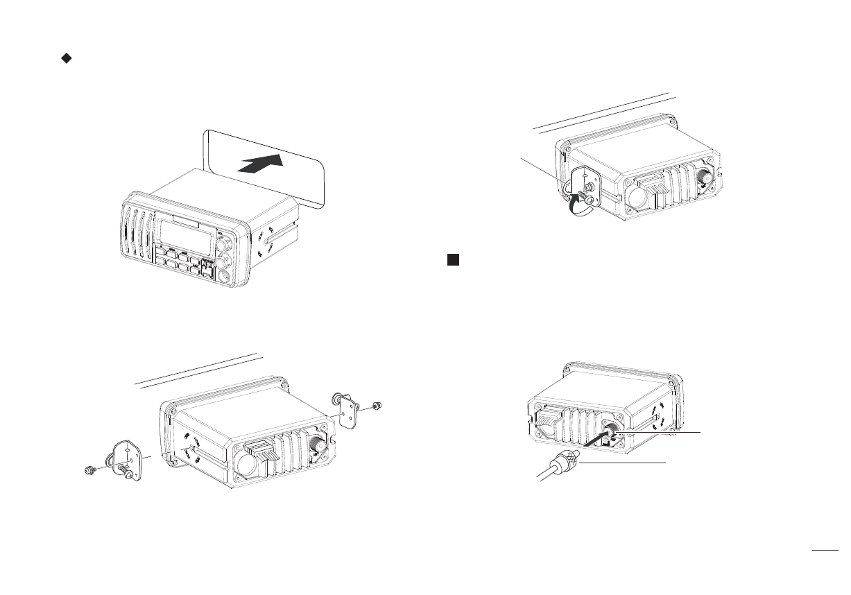
Transceiver Mounting ...............................................................................
Antenna Connection ..................................................................................
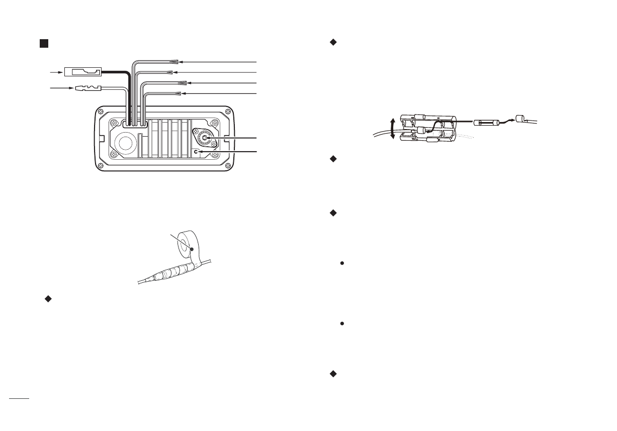
Installation of Connecting Cables ...........................................................
Dimensions ...................................................................................................
PANEL DESCRIPTION
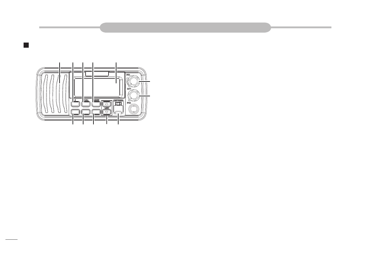
Front Panel ...................................................................................................
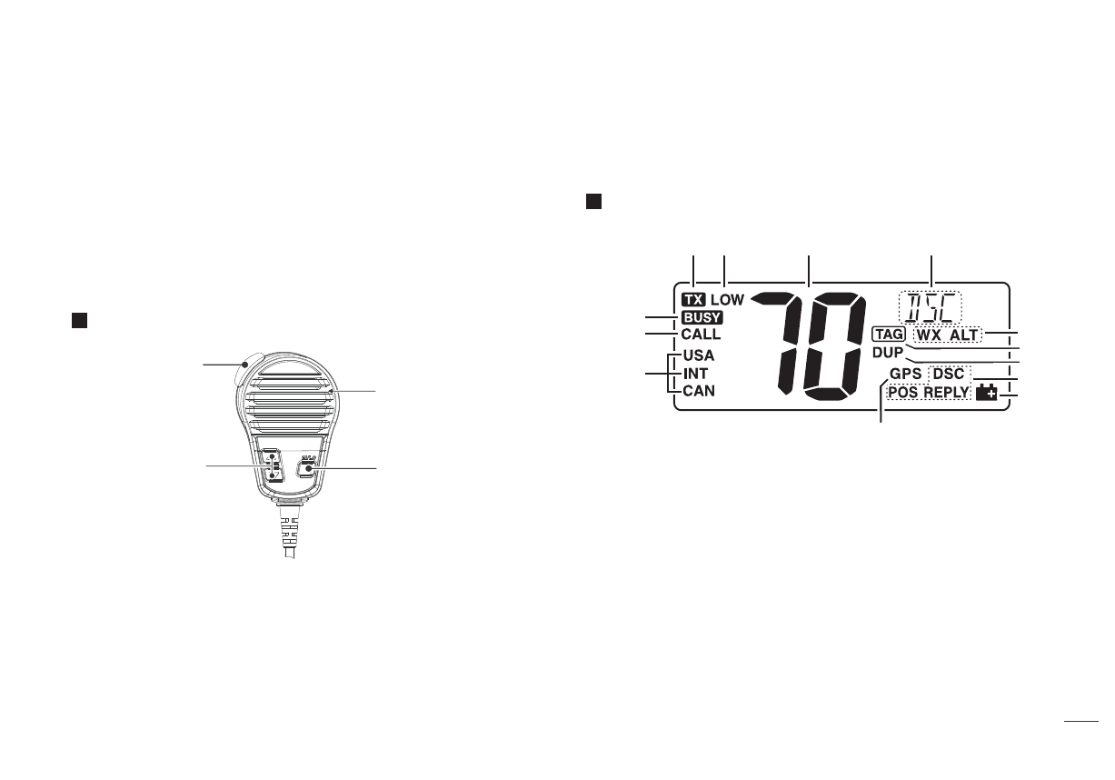
Mircophone ...................................................................................................
Function Display ..........................................................................................
BASIC OPERATION
Power ON/OFF ............................................................................................
Transmitting and Receiving.......................................................................
Channel Group Selection...........................................................................
Channel Selection .......................................................................................
Call Channel Programming ......................................................................
Channel Comment ......................................................................................
Display Backlight .........................................................................................
Vibration Water Draining Function ...........................................................
Microphone Lock Function ........................................................................
SCAN OPERATION
Scan Types ...................................................................................................
Setting TAG Channels ...............................................................................
Starting a Scan ............................................................................................
DUALWATCH / TRI-WATCH
Description ....................................................................................................
Operation........................................................................................................
DSC OPERATION
MMSI Code ..................................................................................................
DSC Address ID ..........................................................................................
GPS Positioning...........................................................................................
Distress Call ..................................................................................................
Individual Call ...............................................................................................
Group Call ....................................................................................................
All Ships Call ................................................................................................
Geographical Area Call ..............................................................................
Position Request Call .................................................................................
SET MODE
Set Mode Operation ...................................................................................
Set Mode Items ...........................................................................................
VHF MARINE RADIO CHANNEL LIST ..................................................
SPECIFICATIONS ......................................................................................
TROUBLESHOOTING ...............................................................................
Position Report Call ....................................................................................
Polling Call....................................................................................................
Test Call ........................................................................................................
Received Messages ...................................................................................
1
1
2
3
4
5
6
6
8
8
8
8
9
10
10
10
10
11
11
11
12
12
13
13
17
18
21
23
24
24
25
26
27
29
30
32
32
34
35
35
CONTENTS
............................................................................................. 31
ATIS OPERATION
Set ATIS ID
ATIS ON/OFF
................................................................................................. 31

1
The following accessories are supplied:
ITEM QUANTITY
DC Power Cable
Spare Fuse
Mounting Bracket
Mounting Screw Package
Instruction Manual
1
PREPARATION
Transceiver Mounting
Using the Supplied Mounting Bracket
Supplied Accessories
The universal mounting bracket supplied with your transceiver allows
overhead or dashboard mounting.
1. Fix the mounting bracket to overhead or dashboard with the
screws and mount the transceiver to the mounting bracket with the
knob bolts.
2. Adjust the transceiver so that the face of the transceiver is at 90°to
your line of sight when operating it and tighten the knob bolts so
that the transceiver is securely mounted.
Notice: You may use a spongy cushion between the transceiver
and mounting bracket to reduce the vibration.
supplied
1
1
1
1

2
Embedded Mounting
Antenna Connection
Bolt
AntennaConnector
CoaxialFeederConnector
ToAntenna
1. Cut a hole into the instrument panel (or wherever you plan to
mount the transceiver).
2. Slide the transceiver through the hole as shown below.
3. Attach the clamps on both sides of the transceiver with 2 supplied
bolts.
4. Tighten the end bolts on the clamps so that the clamps press
firmly against the inside of the instrument control panel.
Please connect an antenna before transmitting. Select the antenna with
the corresponding frequency and install on the ANT antenna base. Use
the antenna and coaxial feeder with the same natural impedance 50Ω.
Notice: Do not transmit before connecting the antenna, it will ruin the
transceiver.

Installation of Connecting Cables
DC Power Connector (1-Black, 2-Red)
Fuse Replacement
Ground Terminal (3- Screw Hole)
NMEA In/Out Lead
Connect a PC or navigation equipment (4-White):
Connect a GPS receiver (5-Red):
Clone Lead (6-Blue)
3
Antenna
4
5
6
7
1
2
3
When connecting the external speaker, GPS, DC power supply,
computer and navigation device by the rear panel cable end, cover the
connectors and cables with rubber vulcanzing tape as below, to
prevent water seeping into the transceiver.
Red - Positive(+), Black - Negative(-).The output voltage of the
connected DC power supply must be 13.8V. Do not connect the
transceiver to the 24V storage battery. If the current supplied to the
transceiver is insufficient, the display may darken during transmission
or the transmitting output power may drop significantly.
One fuse is installed in the supplied DC power cable. If a fuse blows
or the transceiver stops functioning, track down the source of the
problem first, then replace the damaged fuse with a new, rated one.
Notice: Please power off transceiver before replacing the fuse, the
required fuse is DC15A.
Connect this terminal to a vessel ground to prevent electrical shocks
and interference from other equipment occurring. Use a PH M3×6
mm screw (not supplied).
Through the rear panel cable, this transceiver can connect GPS input
signals from GPS receivers, and can also output GPS signals to
other devices.
Used to output position data received from other ships to a
computer or navigation device.
Transceiver output signal conforms to NMEA0183 version 3.01
sentence formatters DSC, DSE compatible .
Used for ship position indication.
A NMEA0183 ver. 2.0 or 3.01 (sentence formatters RMC, GGA,
GNS, GLL) compatible GPS receiver is required.
Connect a cloning cable.
VulcanzingTape

Dimensions
4
163.4
78.2
37.18
60.25
73.99
160.15
148.05
28.15
139.3
External Speaker Lead (7-Yellow)
Connect an external speaker.

PANEL DESCRIPTION
Front Panel
Channel 16 / Call Channel Key [16]1.
→
Channel/ Weather Channel/ Watch Key [CH/WX] (DUAL)
2.
→
3. DSC Menu Key [MENU] (MMSI)
4. Scan/ TAG Key [SCAN] (TAG)
6. Enter Key [ENT]
Press to set the DSC menu, a channel comment, etc.
7. [▲][▼]/[U/I/C]
5. Clear Key [CLR]
Press to clear setting, or exit DSC menu.
5
Press to select Channel 16.
Press and hold for 1 second to select Call channel (Default
Channel 9).
“CALL” appears when the Call channel is selected, then press
and hold this key for 3 seconds to enter call channel
programming mode.
Simultaneously press and hold [CH/WX] and [16] Key to enter
channel comment programming mode.
While in the channel comment programming mode, press to
move the cursor backward.
While pressing and holding this key, power on the transceiver to
enter set mode.
→
→
→
→
→
Press to select regular channel or weather channel.
Press and hold this key for 1 second to start Dual-watch or Tri-
watch.
Press to stop Dual-watch or Tri-watch when either is activated.
While in channel comment programming mode, press this key
to move the cursor forward.
→
→ →
→
Press to enter the DSC menu.
Press and hold this key for one second to display the MMSI
code on the channel comment display.
→
Press to start/ stop normal scan or priority scan.
Press and hold this key for 1 second to set or clear the current
channel as a TAG (scanned) channel.
The favorite channels can be set by the TAG channel setting.
Press and hold [HI/LO] key on MIC and [SCAN] for 3 seconds to
clear all TAG channels in the selected channel group.
→
→
→
Press to select operating channel, Set mode setting, DSC menu
items etc.
While pressing and holding [SCAN] key, press [▲] or [▼] to
adjust the brightness of the LCD and key backlight.
→
CH/WX
16 MENU
SCAN CLR ENT
4 5 6 7
1 2 3
10
9
Speaker Display
8
→
→

Microphone
PTT Switch [PTT]
1.
Press and hold to transmit; Release to receive.
Channel Up/Down Keys [▲][▼]
2.
Transmit Power Key [HI/LO]
3.
→ Press to select high or low output power.
Some channels are set to low power only.
Channel Number Readout1.
Low Power Icon
2.
Appears when low power is selected.
Transmit Icon
3.
Appears when transmitting.
Busy Icon
4.
Function Display
6
MIC
3
2
1
→Press both keys to sequentially select the USA, International or
Canadian channel groups.
While pressing and holding both keys, power on to activate
vibration draining function.
→
Press and hold this key for 3 seconds to transmit a Distress
call.
Rotate to set the squelch level.
10. Power/Volume Knob [VOL]
Rotate to power ON/OFF the transceiver and adjust the volume.
8. Distress Key [DISTRESS]
9. Squelch Knob [SQL]
→Press to select operating channel, Set mode setting etc.
When the favorite channel function is activated, press [▲][▼]
key to select the favorite channels in the selected channel
group in sequence.
→
Whilepressingandholding[HI/LO]key,powerontoturnthe
microphonekeypadlockfunctionON/OFF.
→
Indicates the selected operating channel number. (Refer to
Channel List).
In the Set mode, display the selected option.
→
→
Appears when receiving a signal or when the squelch opens.
7
123
12
11
10
9
8
4
5
6
13

8.
Weather Channel Icon
12.
→ “WX” appears when a weather channel is selected.
→
9.
Duplex Icon
10.
TAG Channel Icon
11.
Appears when a duplex channel is selected.
Appears when a TAG channel is selected.
Channel Comment Display
13.
→
7
Low Battery Icon
DSC Icon
→ “DSC”appears when a DSC call is received.
7. GPS Icon
→ Appears while valid position data is received.
→ Disappears when no GPS receiver is connected.
Call Channel Icon
Channel Group Icon
5.
6.
Appears when the Call channel is selected.
Indicates whether U.S.A. “USA”, International “INT” or Canadian
“CAN” channel group is selected.
Appears when the battery voltage drops to approximately 10.8V or
below.
“POS REPLY” appears when a Position Reply call or a
Position Report Reply call is received.
→
“WX ALT” appears when the weather alert function is in use;
blinks when an alert tone is received.
Channel comment appears if programmed.
“SC” blinks during priority scan; “SCAN” blinks during normal
scan.
“DW” blinks during Dual-watch; “TW” blinks during Tri-watch.
→
→

BASIC OPERATION
1. Rotate [VOL] clockwise to power on.
Rotate [VOL] counter-clockwise to power off.
2.
1.
2.
When receiving a signal, “ ”appears and audio is heard
Power ON/OFF
Transmitting and Receiving
Transmitting
Receiving
Rotate [VOL] knob to adjust the volume.
Rotate [SQL] clockwise until the noise just disappears.
Channel Group Selection
Channel Selection
Channel 16
8
1. Press [HI/LO] key on the microphone to select the output power if
necessary.
“LOW” appears when low power is selected.
Choose low power for short range communication, choose high
power for longer distance communication.
Some channels are with low power only.
2. Press and hold [PTT] key to transmit, then speak into the
microphone.
“ ”appears.
CH70 is for DSC transmitting only.
3. Release [PTT] to receive.
Notice: Do not transmit before connecting the antenna, this will
ruin the transceiver.
If the TOT function is enabled by the PC programming software,
the transmission time-limited protection function prohibits
continuous transmission for a long time.
from the speaker.
The transceiver is pre-programmed with 57 USA, 57 International and
61 Canadian channels. These channel groups may be specified for the
operating area.
1. Press [CH/WX] to select a regular channel.
If a weather channel appears, press [CH/WX] again.
2. Press [U/I/C] (both [▲] and [▼]) to change the channel group.
USA, International and Canadian channel groups can be
selected in sequence.
3. Press [▲] or [▼] to select a channel.
“ ” appears for duplex channels.
“ ” appears when a simplex channel is selected.
Channel 16 is the distress and safety channel. It is used for
establishing initial contact with a station and for emergency
communications. Channel 16 is monitored during both Dual-watch
and Tri-watch. While in the stand-by mode, you must monitor
Channel 16.
1. Press [16] to select Channel 16.
2. Press [CH/WX] to return to the previous display, press [▲] or [▼]
to select operating channel.

Convenient Operation:
Weather Channels
4.
5.Press [16](9) to program the displayed channel as the Call channel.
Channel 9 (Call Channel)
Call Channel Programming
Press [▲] or [▼] to select a desired channel.
Press [CLR] to cancel and exit.
9
Scrolls
Displays
When the favorite channel function is turned ON, press [▲] or [▼] to
select the favorite channels in sequence in the selected channel
group.
The Favorite channels are set by the TAG channel setting.
Each regular channel group has a separate leisure-use Call channel
(Default Channel 9). The call channel is monitored during Tri-watch.
1. Press and hold [16](9) for 1 second to select the Call channel of
the selected channel group. “CALL” and Call channel number
appear.
2. Press [CH/WX] to return to the previous display, press [▲] or [▼]
to select operating channel.
The transceiver has 10 weather channels.
The transceiver can automatically detect a weather alert tone on the
selected weather channel while receiving on a regular channel or
while scanning.
1. Press [CH/WX] to select between weather channel and regualr
channel.
“ ” appears when a weather channel is selected.
“ ” appears when the Weather Alert function is in use.
2. Press [▲] or [▼] to select a channel.
Call channel is used to select Channel 9 (default), however, you can
program the Call channel with your most offer-used channel in each
channel group for quick recall.
1. Press [U/I/C] (both [▲] and [▼]) one or more times to select the
desired channel group (U.S.A., International or Canadian) to be
programmed.
2. Press and hold [16](9) for 1 second to select the Call channel of
the selected channel group.
“CALL” and the Call channel number appear.
3. Press and hold [16](9) again for 3 seconds (until a long beep
changes to two short beeps) to enter Call channel programming
mode.
Channel number starts blinking.
WeatherAlertFunctionOFF WeatherAlertFunctionON
Scrolls
Displays

Channel Comment
Display Backlight
Vibration Water Draining Function
Microphone Lock Function
10
Memory channels can be labeled with a unique alphanumeric ID of up
to 10 characters.
When the comment is more than 7 characters long, screen scroll
displays.
Capital letters, small letters (except f, j, k, p, s, v, x, z), 0 to 9, some
symbols (= * + - . /) and space can be used.
1. Select the desired channel.
Cancel Dual-watch, Tri-watch or scan in advance.
2. While pressing and holding [CH/WX], press [16] to program the
channel comment.
A cursor and the first character start blinking alternately.
3. Press [▲] or [▼] to select the desired character.
Press [16] or [CH/WX] to move the cursor forward or backward,
respectively.
4. Repeat step 3 to input all characters.
5. Press [ENT] to input and set the comment.
Press [CLR] to cancel and exit the programming mode.
The cursor and the character stop blinking.
The LCD display and keys can be backlit for better visibility under low
light conditions.
※ While pressing and holding [SCAN], press [▲] or [▼] to adjust the
brightness of the LCD and key backlight.
The backlight is selectable in 3 levels and OFF.
Vibration helps drain water away from the speaker housing (water that
might otherwise muffle the sound coming from the speaker). The
transceiver makes a vibrating noise when this function is being used.
1. While pressing and holding [▲] and [▼], rotate [VOL] and power
ON to activate the Vibration Water Draining function.
“VIB WATER” appears.
2. A low beep tone sounds while [▲] or [▼] keys are held to drain
water, regardless of [VOL] control setting.
The transceiver never accepts any key operations while the
Vibration function is activated.
The microphone lock function electrically locks [▲] and [▼] keys on the
supplied microphone. This prevents accidental channel changes and
function access.
While pressing and holding [HI/LO] on the microphone, power ON to
toggle the microphone lock function ON or OFF.
Scrolls

Setting TAG Channels
SCAN OPERATION
Scan Types
Setting/Clearing All Tagged Channels
Starting a Scan
Set scan resume timer in the Set mode.
11
The transceiver has normal scan and priority scan. (Refer to set mode
operation).
When the weather alert function is turned ON, the previously selected
(last used) weather channel is also scanned.
Set the TAG channels (scanned channels) before scanning. Clear the
TAG channels which inconveniently stop scanning.
Normal Scan: Normal scan searches through all TAG channels in
sequence. Channel 16 is not checked unless Channel 16 is set as a
TAG channel.
Priority Scan: Priority scan searches though all TAG channels in
sequence while monitoring Channel 16.
For more efficient scanning, you can add desired channels as TAG
channels or clear the TAG for unwanted channels.
Channels that are not tagged will be skipped during scanning.
2. Press [▲] or [▼] to select the desired channel to be set as a TAG
channel.
3. Press and hold [SCAN] for 1 second to set the displayed channel
as a TAG channel.
“ ” appears.
4. To cancel the TAG channel setting, press and hold [SCAN] for 1
second again.
“ ” disappears.
1. While pressing and holding [HI/LO] on the microphone, press
[SCAN] for 3 seconds to clear all TAG channels in the selected
channel group.
2. Repeat above procedure to set all TAG channels.
1. Press [SCAN] to start normal scan or priority scan.
“SCAN” blinks during normal scan; “SCAN” blinks and “16”
appears during priority scan.
Channel 16 is monitored during priority scan. “16” blinks when a
signal is received on Channel 16.
Press [▲] or [▼] to change the scanning direction.
A beep tone sounds and “SC 16” blinks on channel comment
display when a signal is received on Channel 16 during priority
scan.
2. To stop the scan, press [SCAN].
Setting/Clearing a Single Tagged Channel
1. Press [U/I/C] (both[▲]and[▼])to select the desired channel group.
NormalScan PriorityScan

Operation
DUALWATCH/TRI-WATCH
Description
12
The transceiver has Dualwatch and Tri-watch.
Dualwatch monitors Channel 16 while you are receiving on another
channel.
Tri-watch monitors Channel 16 and the Call channel while receiving on
another channel.
1. Press and hold [CH/WX] for 1 second to start Dualwatch or Tri-
watch.
“DW” blinks during Dualwatch; “TW” blinks during Tri-watch.
A beep tone sounds and “16” blinks when a signal is received
on Channel 16.
2. Press [CH/WX] again to cancel Dualwatch or Tri-watch.
Dualwatch
CallChannel
Tri-watch

MMSI Code
DSC OPERATION
MMSI Code Programming MMSI Code Checking
DSC Address ID
Programming Address ID
Scrolls
13
The 9-digit MMSI (Maritime Mobile Service Identity: DSC self ID) code
can be programmed at power ON.
Notice: This code programming can be performed only twice. After the
code programming, it can be changed only by your dealer or distributor.
The MMSI code can be programmed by PC software and also
manually set on this transceiver.
1. Rotate [VOL] to power OFF.
2. While pressing and holding [▲], power ON to enter MMSI
code programming mode.
3. After the display appears, release [▲].
4. Press [MENU] to enter the DSC menu.
5. Press [▲] or [▼] to select “MMSI”, then press [ENT], a cursor
starts blinking.
6. Press [▲] or [▼] to select the specified MMSI code.
Press [CH/WX] or [16] to move the cursor forward or backward.
7. After programming the 9-digit MMSI code, press [ENT],
“CONFIRMATION” scrolls in the channel comment display.
8. Press [ENT], then input the same MMSI code as step 6 for the
confirmation.
9. Press [ENT] to set the code.
Press [CLR] to cancel and exit the programming mode, if desired.
If a different code is input, “INCORRECT” appears. In that case,
press [ENT] to repeat steps 6 to 8 again.
The 9-digit MMSI (DSC self ID) code can be checked.
While in the stand-by mode, press and hold [MENU](MMSI) for 1
second to display the 9-digit MMSI (DSC self ID) code.
The MMSI code is displayed and scrolls in the channel comment
display.
When no MMSI code is programmed, “NO MMSI” appears and
prompt tone sounds.
A total of 100 9-digit DSC address IDs can be programmed and
named with up to 10 characters.
1. Press [MENU] to enter the DSC menu.
2. Press [▲] or [▼] to select “ADDRESS”, then press [ENT].
Scrolls

1. Press [MENU] to enter the DSC menu.
2. Press [▲] or [▼] to select “ADDRESS”, then press [ENT].
Deleting Address ID
3. Press [▲] or [▼] to select “DEL INDV ID”, then press [ENT].
Programming Group ID
1.
3. Press [▲] or [▼] to select “ADD GROUP ID”, then press [ENT].
14
3. . Press [▲] or [▼] to select “ADD INDV ID”, then press [ENT].
4. Press [▲] or [▼] to input 9-digit individual ID, then press [ENT].
Press [CH/WX] or [16] to move the cursor forward or backward.
Press [CLR] to cancel and exit the programming mode.
5. Press [▲ ] or [▼] to input a 10-character ID name.
Press [CH/WX] or [16] to move the cursor forward or backward.
Press [CLR] to cancel and exit the programming mode.
6. Press [ENT] to save setting and return to normal operation.
When no address ID is programmed, “NO ID” is displayed.
4. Press [▲] or [▼] to select a desired ID name for deleting, then
press [ENT], “READY” appears.
5. Press [ENT] to delete the selected address ID and return to normal
operation.
Press [MENU] to enter the DSC menu.
Press [▲] or [▼] to select “ADDRESS”, then press [ENT].
2.
Scrolls
Scrolls
Scrolls

Deleting Group ID
Auto Switch Function
15
4. Press [▲ ] or [▼] to input a 9-digit ID number, then press [ENT].
Press [CH/WX] or [16] to move the cursor forward or backward.
Press [CLR] to cancel and exit the programming mode.
Notice: The first one digit is specified ‘0’ for Group ID. The first two
digits are ‘0’ for Coast station ID.
5. Press [▲ ] or [▼] to input a 10-character ID name.
Press [CH/WX] or [16] to move the cursor forward or backward.
Press [CLR] to cancel and exit the programming mode.
6. Press [ENT] to save setting and return to normal operation.
1. Press [MENU] to enter the DSC menu.
2. Press [▲] or [▼] to select “ADDRESS”, then press [ENT].
3. Press [▲] or [▼] to select “DEL GROUP ID”, then press [ENT].
When no group ID is programmed, “NO ID” is displayed.
4. Press [▲] or [▼] to select a desired ID name for deleting, then
press [ENT], “READY” appears.
5. Press [ENT] to delete the selected group ID and return to
normal operation.
By regulation, after receiving a Distress call, the transceiver basically
switches the operating channel to Channel 16. However, when this
setting is set to “OFF,” the function enables the transceiver to remain
on the operating channel even after receiving a Distress call.
1. Press [MENU] to enter the DSC menu.
2. Press [▲] or [▼] to select “AUTO SW”, then press [ENT].
3. Press [▲] or [▼] to select the Auto Switch “ON” or “OFF”(Default
“ON”).
Press [CLR] to cancel and exit the setting.
ON: The transceiver automatically switches the operating
channel to Channel 16 after receiving a Distress call.
OFF: The transceiver remains on the operating channel even
after receiving a Distress call.
4. Press [ENT] to save setting and return to normal operation.
Scrolls

GPS Positioning
Position Indication
Programming Position and Time
17
1. Press [MENU] to enter the DSC menu.
2. Press [▲] or [▼] to select “OFFSET TIME”, then press [ENT].
3. Press [▲] or [▼] to set the offset time from the UTC (Universal
Time Coordinated) time.
Press [CH/WX] or [16] to move the cursor forward or backward.
Press [CLR] to cancel and exit the setting.
4. Press [ENT] to program and then to exit the programming mode.
Notice: The local time indication is not available when the GPS
receiver (sentence formatter RMC) is connected, the transceiver’s
display indicates UTC time only.
When a GPS receiver is connected, the transceiver displays the
current position data with update once per second.
A NMEA0183 ver. 2.0 or 3.01 (sentence formatters RMC, GGA, GNS,
GLL) compatible GPS receiver is required.
Latitude, Longitude and UTC time data scroll in sequence in the
channel comment display.
“NO POSITION” and “NO TIME” scroll when no GPS is connected.
When the GPS receiver is compatible with several sentence
formatters, the order of input precedence is RMC, GGA, GNS
and GLL.
A Distress call should include the ship’s position and time data. If no
GPS is connected, your position and UTC (Universal Time
Coordinated) time should be input manually. They are included
automatically when a GPS receiver is connected (NMEA0183 ver. 2.0
or 3.01).
“??” may blink instead of position and time indications when the GPS
data is invalid, or has not been manually updated after 4 hours.
1. Press [MENU] to enter the DSC menu.
2. Press [▲] or [▼] to select “POSITION INPUT”, then press [ENT].
3. Press [▲] or [▼] to input your latitude data, then press [ENT] to set
your longitude data.
Press [CH/WX] or [16] to move the cursor forward or backward.
Press [▲] or [▼] to edit N(North Latitude) or S(South Latitude)
when the cursor is on the ‘N’ or ‘S’ position;
Press [▲] or [▼] to edit W(West Longitude) or E(East
Longitude) when the cursor is on the ‘W’ or ‘E’ position.
Press [CLR] to cancel and exit the setting.
Scrolls
Scrolls
Scrolls

Automatic Acknowledgement
Offset Time
16
Auto Tune Timer
This is the amount of time after receiving a Distress call before the
transceiver switches to Channel 16.
1. Press [MENU] to enter the DSC menu.
2. Press [▲] or [▼] to select “AUTO TUNE”, then press [ENT].
3. Press [▲] or [▼] to set the Auto Tune Timer period to between 10-
600 seconds or turn OFF, default 30 seconds.
Press [CLR] to cancel and exit the setting.
OFF: Turn OFF the Auto Tune Timer.
10-600 Seconds: After receiving a Distress call, the transceiver
remains on the operating channel for the programmed time
period between 10 and 600 seconds, and then automatically
switches to Channel 16.
※ Within the programmed timer period, the following action can be
taken:
When the [ENT] key is pressed, immediately switches to
Channel 16.
When the [CLR] key is pressed, the Auto tune timer is cancelled
and the transceiver remains on the operating channel.
4. Press [ENT] to save setting and return to normal operation.
The action of the transceiver may differ, depending on the
combination of the Auto Switch function and the Auto Tune Timer
settings.
Auto Tune Timer
OFF ON (10-600 Seconds)
Auto
Switch
ON
The transceiver
automatically switches to
Channel 16.
The transceiver remains on the operating channel for the
programmed time period, and then automatically switches
to Channel 16.
Within the programmed timer period, the following action
can be taken:
• When the [ENT] key is pressed, immediately switches to
Channel 16.
• When the [CLR] key is pressed, remains on the operating
channel since the Auto Tuner timer is cancelled.
OFF
Thetransceiver remains
on the operating channel.
“AUTO SW OFF” scrolls
in the channel comment
display.
This item sets the automatic acknowledgement function ON or OFF.
When a position request or polling request call is received, transceiver
automatically transmits a position reply or polling reply call.
1. Press [MENU] to enter the DSC menu.
2. Press [▲] or [▼] to select “AUTO ACK”, then press [ENT].
3. Press [▲] or [▼] to select the Automatic Acknowledgement
function“ON” or “OFF”.
4. Press [ENT] to save setting.
Press [CLR] to cancel and exit the setting.
This item sets the offset time from the UTC (Universal Time
Coordinated) time.
Scrolls
Scrolls
Table of contents
Other Onwa Transceiver manuals
Popular Transceiver manuals by other brands

Genave
Genave Mobiline II Maintenance manual

FreeFlight
FreeFlight FWF-125 installation manual

TTI
TTI Freequency TCB-880 Service manual

Yaesu
Yaesu VXA-210 specification

Kanga Products
Kanga Products Bassinet Manual and user guide

Delta Electronics
Delta Electronics Multi-Rate CWDM SFP Transceiver LCP-155 CWDM Specification sheet

Wireless Technologies
Wireless Technologies WTE TReX user manual

Oceanscience
Oceanscience HydroLink ML2 Series quick start guide

Thrane&Thrane
Thrane&Thrane TT-3020C Configuration manual

Standart
Standart C510A Service manual

Kenwood
Kenwood TH-225A instruction manual

SG Security Communications
SG Security Communications Skyroute UT installation manual