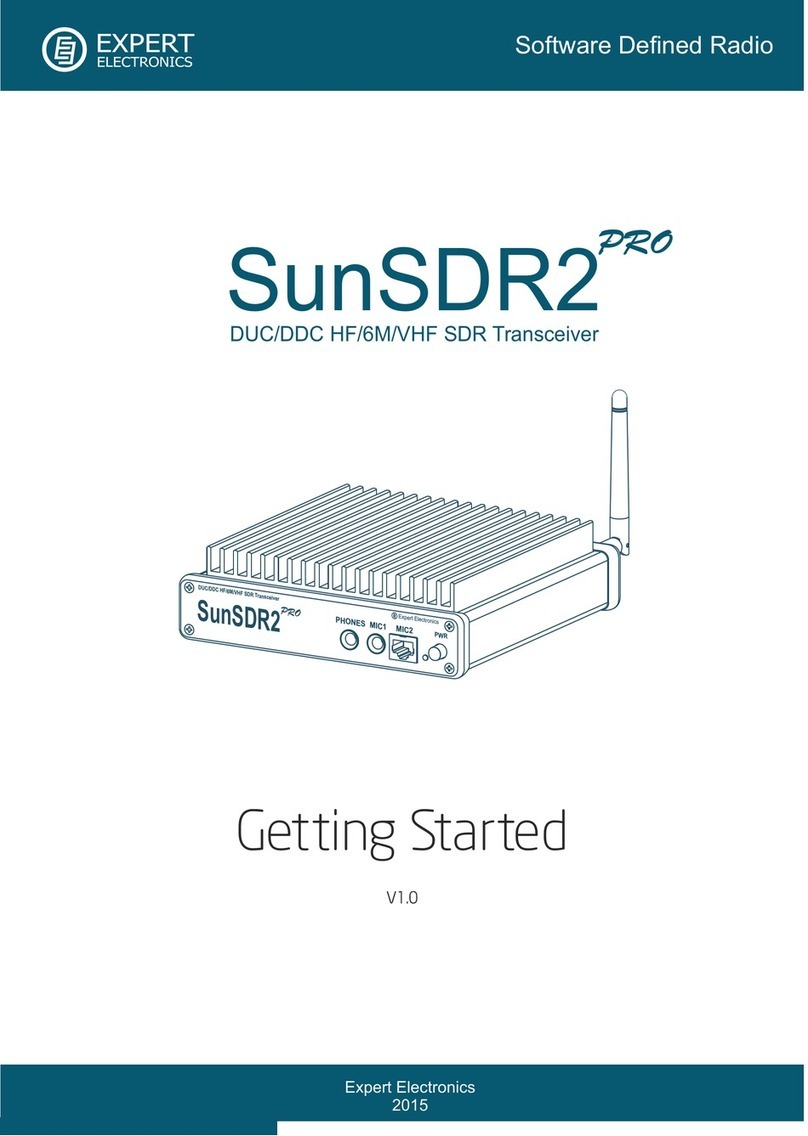
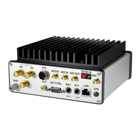
Expert Electronics SunSDR2 Pro User manual

Expert Electronics
© 2018 Expert Electronics
SunSDR2 PRO
USER MANUAL
1.5.0
HF/50 MHz/VHF TRANSCEIVER
Direct Sampling SDR transceiver


3
SunSDR2 PRO User Manual © 2018 Expert Electronics
TABLE OF CONTENTS
1. READ IT FIRST 6
1.1 Congratulations .......................................................................................... 6
1.2 Features ...................................................................................................... 6
1.3 Supplied accessories ................................................................................... 7
1.4 Precautions ................................................................................................. 8
1.5 ExpertSDR2 Software License Agreement ................................................ 9
1.6 Copyrights ................................................................................................. 10
1.7 Contacts .................................................................................................... 10
2. FRONT PANEL DESCRIPTION 11
3. REAR PANEL DESCRIPTION 12
3.1 Antenna .................................................................................................... 13
3.2 Grounding ................................................................................................. 14
3.3 Accessories ............................................................................................... 14
3.4 External Linear Amplifier ......................................................................... 15
3.5 External Control devices .......................................................................... 16
3.6 Reference input ........................................................................................ 17
3.7 Transverter connection ............................................................................ 17
3.8 DAC OUT low power output ..................................................................... 17
3.9 ADC IN and RX OUT .................................................................................. 18
4. CONNECTORS PIN-OUT 19
4.1 MIC1 .......................................................................................................... 19
4.2 MIC2 .......................................................................................................... 19
4.3 EXT CTRL .................................................................................................. 20
5. ExpertSDR2 SOFTWARE DESCRIPTION 22
5.1 Global controls panel ................................................................................ 22
5.2 Software transceiver settings .................................................................. 26
5.2.1 Transceiver control panel ......................................................................... 26
5.2.2 Frequency and S-meter indicators ............................................................. 40
5.2.3 DSP control panel .................................................................................... 42
5.2.4 Panorama description .............................................................................. 44
5.2.4.1 Spectrum Scope ................................................................................... 45
5.2.4.1.1 Spectrum Scope scaling ...................................................................... 45
5.2.4.2 Waterfall ............................................................................................. 46
5.2.5 Status bar ............................................................................................... 46
5.3 Options ...................................................................................................... 48
5.3.1 Device menu ........................................................................................... 48
5.3.1.1 Mic .................................................................................................... 49
5.3.1.2 VAC ................................................................................................... 50
5.3.1.3 VOX .................................................................................................. 51

4
SunSDR2 PRO User Manual © 2018 Expert Electronics
TABLE OF CONTENTS
5.3.1.4 DSP ................................................................................................... 51
5.3.1.5 TX .................................................................................................... 54
5.3.1.6 CW .................................................................................................... 56
5.3.1.7 Ext Ctrl ............................................................................................... 57
5.3.1.8 Expert ................................................................................................ 58
5.3.2 Sound card menu .................................................................................... 61
5.3.2.1 Sound card .......................................................................................... 61
5.3.2.2 Line output .......................................................................................... 62
5.3.3 Display menu .......................................................................................... 63
5.3.3.1 Main window ........................................................................................ 63
5.3.3.2 Spectrum ............................................................................................ 64
5.3.3.3 Waterfall ............................................................................................. 67
5.3.3.4 Grid ................................................................................................... 68
5.3.3.5 Filter .................................................................................................. 68
5.3.3.6 Background ......................................................................................... 69
5.3.3.7 Indicators ........................................................................................... 70
5.3.4 CAT menu .............................................................................................. 71
5.3.4.1 RX1 receiver ........................................................................................ 71
5.3.4.2 RX2 receiver ........................................................................................ 73
5.3.5 Panel menu ............................................................................................ 73
5.3.6 Features menu ........................................................................................ 78
5.3.7 ExpertSync menu .................................................................................... 79
5.3.8 CW Skimmer menu ................................................................................. 79
5.3.9 Shortcuts menu ....................................................................................... 81
5.3.10 IQ Recorder menu ................................................................................... 82
5.3.11 TCI menu ............................................................................................... 82
5.3.12 Spot settings menu .................................................................................. 83
6. TECHNICAL CHARACTERISTICS 84
6.1 Receiver .................................................................................................... 84
6.2 Transmitter ............................................................................................... 85
6.3 Other ......................................................................................................... 86
7. TRANSCEIVER OPERATIONS 87
7.1 Local operation ......................................................................................... 87
7.2 Remote operation .................................................................................... 87
7.3 Frequency Tuning ..................................................................................... 87
7.4 Antenna switch ......................................................................................... 88
7.5 Voice Recorder Operation ........................................................................ 89
7.6 Transverter mode operation .................................................................... 90
7.7 Split operation .......................................................................................... 90
7.7.1 SPLIT + Sub RX Operation ....................................................................... 91
7.8 RIT/XIT .................................................................................................... 91
7.8.1 RIT ........................................................................................................ 91
7.8.2 XIT ........................................................................................................ 92
7.9 Digital modes operation ........................................................................... 93
5
SunSDR2 PRO User Manual © 2018 Expert Electronics
TABLE OF CONTENTS
8. RESET DEFAULT SETTINGS 94
9. REGULATORY REQUIREMENTS 95

6
SunSDR2 PRO User Manual © 2018 Expert Electronics
READ IT FIRST
1READ IT FIRST
1.1 Congratulations
On behalf of the whole Expert Electronics company, we'd like to thank you for purchasing one of
the best modern SDR transceivers!
The SunSDR2 PRO transceiver is the best size/capability SDR transceiver which is perfect for
contests and DXpeditions!
1.2 Features
The SunSDR2 PRO transceiver was designed for advanced operation on HF and VHF bands,
even the most demanding operator will be surprised by its capabilities. Modern hardware along
with the ExpertSDR2 software makes this high-performance SDR transceiver the perfect base
station and at the same time perfectly suitable for field operations.
Main features and capabilities of the transceiver
·
Independent RX path based on DDC (Direct Down-Conversion) architecture
·
Independent TX path based on DUC (Direct Up-Conversion) architecture
·
ExpertRemote system provides full remote control of the transceiver
·
An opportunity to use the transceiver in the SO2V mode
·
Full or half-duplex mode*
·
2 software receivers (each up to 312 kHz) + SubRX for each of them (4 slices total) +
independent wideband Bandscope up to 80 MHz
·
Antenna switch with 2 HF antenna connectors and separate VHF antenna connector
·
Supports use of VHF transverters
·
An opportunity to use the transceiver as a signal generator via DAC OUT connector
·
Built-in power-meter and SWR-meter for HF bands
·
ExtCTRL connector to control external devices with 8 powerful keys with open collector
·
Ethernet LAN interface provides fast and reliable connection to PC
·
ALC connector for external power amplifiers**
·
TCI interface for seamless connection with third-party software like SDC (with its own
Skimmer), LogHX, SWISSLOG and RUMlog, more are coming
·
Professional TX processing module provides the most advanced tuning capability for
voice operation
·
Small delay in CW mode (about 10 ms)

7
SunSDR2 PRO User Manual © 2018 Expert Electronics
READ IT FIRST
*
Full-duplex mode is supported by the transceiver's hardware but is not implemented in the
firmware and software yet. This mode will be implemented in future versions of ExpertSDR2
software.
** ALC functionality is supported by the transceiver's hardware but is not implemented in the
ExpertSDR2 software. It will be supported in the ExpertSDR2 1.3 software release.
PC requirements
·
CPU Intel Core i3 1.6 GHz and higher
·
8GB RAM
·
Video card, minimum resolution 1024x600, 128 MB, OpenGL 1.5 support and higher
·
Local network connector 100 Mbps or 1 Gbps
·
The ExpertSDR2 works with Windows 7-10, OS Linux Ubuntu x64 and macOS 10.12 and
newer
Block Diagram
1.3 Supplied accessories
·
SunSDR2 PRO transceiver
·
LAN-cable for connection to a local network (1.8m)

8
SunSDR2 PRO User Manual © 2018 Expert Electronics
READ IT FIRST
·
Power cable for connection to a power supply (2m)
·
Audio-adapters JACK 6.3mm to JACK 3.5mm (2 pcs.)
·
RF Cable Mini UHF — HF (PL259) 1Ft (0.3m 1 pc.)
Additional equipment:
Additionally you can purchase the following devices:
·
E-Coder Plus, E-Coder panel or E-Coder mini kit for convenient remote operation
·
PTT footswitch
1.4 Precautions
To prevent any damage to the transceiver, please read these operating rules
carefully before attempting to operate on the air.
·
Carefully read this manual first, otherwise connecting and operating the SunSDR2 PRO could
lead to fatal errors
·
Visually inspect the SunSDR2 PRO transceiver for the absence of mechanic damages before
connecting it to PC
·
Before connecting the SunSDR2 PRO to the AC power line, ensure it is grounded. Never use
the SunSDR2 PRO transceiver without grounding
·
It is forbidden to connect the SunSDR2 PRO to PC with the voltage presence on it or in the
switched condition
·
It is forbidden to use the power supply with the voltage higher than +16 V. Remember! The
transceiver's power is the voltage direct current!
·
Connecting the Transceiver to a PC should be done in accordance with the connection
diagram, given in the Manual
·
If the SunSDR2 PRO was stored in abnormal climatic conditions, it is recommended to keep it
in normal operating temperatures for at least 2 hours before switching on
·
It is forbidden to use and store the Transceiver in the dusted rooms and expose it to direct
sunlight for a long time
·
Before connecting the external devices to connector EXT CTRL read the Manual, learn tables
and diagrams of connecting the external devices
·
DO NOT connect a VGA monitor to EXT CTRL port, you will damage the transceiver!
·
Remember! The transistor switches have limitations of supply voltage and current, going
through them. DO NOT allow polarity reversal!
·
DO NOT use the SunSDR2 PRO in temperatures lower than 0ºC (32ºF) and higher than
+75ºC (167ºF)

9
SunSDR2 PRO User Manual © 2018 Expert Electronics
READ IT FIRST
·
DO NOT emit HF/VHF signal with power more than 1W in the same room or near the
Transceiver
·
DO NOT transmit without a load (dummy load/matched antenna) - it will lead to
overheating of the engaged components and may result in their failure. The same applies to
an unmatched load
·
Avoid the exposure of the atmospheric downfalls on the SunSDR2 PRO and never spill any
liquids (especially aggressive) on it
·
It is forbidden to use the Transceiver during storms!
·
Always disconnect the antenna from the Transceiver when not in use, or if there is a
danger of atmospheric electricity
·
Don't open the Transceiver, it has radio elements, which have high-sensitivity to the static
electricity. This document contains all necessary information about the internal design to
satisfy the Users’ curiosity. To repair the Transceiver, ask the manufacturer
·
Ensure the Transceiver and any connecting cables are free from the effects of
electromagnetic interference and uncontrolled currents and voltages
·
To avoid damage to the Transceiver or causing harmful interference on air, it should only be
operated by licensed HAMs
·
Keep the Transceiver out of the reach of children
·
If the transceiver emits an abnormal odor, or smoke, immediately turn it OFF and remove the
power cable. Contact your closest Expert Electronics dealer for advice
·
Always take great care when moving or transporting the transceiver
·
Ground the antenna-mast and antenna-feeders to avoid accumulation of atmospheric static
electricity on them
·
Always use ferrite beads on antenna and other cables, connected to the transceiver
1.5 ExpertSDR2 Software License Agreement
The ExpertSDR2 software is the proprietary product and intellectual property of Expert
Electronics. It is forbidden to modify, copy or disclose to third parties ExpertSDR2 software
distribution.
Official versions of the software are published on the manufacturer's website in the section
"SunSDR2 PRO Transceiver/Downloads".
New versions of the SunSDR2 PRO transceiver software may have different titles from time to
time. This license agreement applies to all new versions of the software and may be
supplemented and/or amended unilaterally by Expert Electronics.
The manufacturer reserves the right to alter and/or improve the SunSDR2 PRO transceiver
software, adding new features and bug fixes. In this regard, the software may be different from
the description herein. Ask your closest dealer on the availability of new, more complete version

10
SunSDR2 PRO User Manual © 2018 Expert Electronics
READ IT FIRST
of the User Manual, or look for them on the official website of the manufacturer in the section "
SunSDR2 PRO Transceiver / Documentation".
Users of the SunSDR2 PRO transceiver can update the software by themselves, by
downloading from the official website of the Expert Electronics company.
The manufacturer is not responsible for the consequences of the user utilizing an unofficial or
modified version of the ExpertSDR2 software and/or changes the settings or other files which
are related to the ExpertSDR2 functionality.
The manufacturer assumes no responsibility for the material, moral or any other kind of damage,
whether expressed or implied, caused by using of a third-party software.
The manufacturer assumes no responsibility for the material, moral or any other kind of damage,
whether expressed or implied, caused by using of external devices along with the SunSDR2
PRO transceiver.
1.6 Copyrights
Expert Electronics company holds copyrights for the SunSDR2 PRO transceiver, intellectual
property: ExpertSDR2 software and all User Manuals and Instructions for the device and
software.
It is forbidden to present this document as your own, sell it or use it in any other commercial
activity.
Expert Electronics company does not guarantee, that the functions and their qualities described
in this manual, and also combinations which were not described in the manual, comply with the
User purposes, if it is not mentioned in the Manual. Expert Electronics company does bear any
responsibility for the material, moral or other kinds of damage expressed or implied by such
actions.
1.7 Contacts
MANUFACTURER
Expert Electronics
Web-site: www.eesdr.com
E-mail: info@sunsdr.com
You can contact us via mentioned above mail address about: your orders, inquiries, technical
support, software support.

11
SunSDR2 PRO User Manual © 2018 Expert Electronics
READ IT FIRST
2FRONT PANEL DESCRIPTION
#
Name
Description
1
Headphones jack jack
6.3
Here you may connect headphones with 16-30 Ohm impedance or
speakers.
Warning! Never use headphones with a mono connector! If you
have a monophonic headphones, use the stereo 6.3 mm Jack and
connect them to one of the channels.
Warning! Never connect two stereo channels with each other!
Note: Headphones with high impedance may sound quieter.
2
Electret microphone
jack 6.3
Here you may connect an electret microphone from a PC's
headset.
3
Dynamic microphone
Here you may connect a dynamic microphone MH-31 or any other
dynamic microphone with the RJ-45 connector and similar pinout.
Allowed output impedance is 500-600 Ohm.
4
Power and connection
LED indicator
This indicator displays operation modes of the transceiver:
- green color: LAN is active/connected;
- orange color: WiFi is active/connected (when the transceiver
has a WiFi option);
- red color: transmit mode is “ON”;
- blinking green or orange color: network setup state, wait until
blinking stops.
5
Power on/off button
Press the button to power on/off the transceiver.

12
SunSDR2 PRO User Manual © 2018 Expert Electronics
FRONT PANEL DESCRIPTION
3REAR PANEL DESCRIPTION
#
Name
Description
6
WLAN antenna
connector
This connector is installed when the transceiver has a WiFi (WLAN)
option.
7
External reference
oscillator Input 10 MHz
10 MHz CMOS level
input
Appropriate Voltage for this input: 10-13 dB/mW amplitude and
10MHz frequency.
Warning! Improper use or higher voltage may damage the
transceiver!
8
RX OUT
Internal receiver's front-end output.
Warning! Improper use or higher voltage may damage the
transceiver!
9
ADC IN
Direct input, bypassing Band Pass Filters (BPFs). ADC IN
connector may be used for connection of the receiving antennas,
transverters, additional BPFs, preamplifiers, attenuators etc.
Warning! Improper use or higher voltage may damage the
transceiver!
10
DAC OUT
Direct output, bypassing Band Pass Filters (BPFs). The output can
be used for connection of the external power amplifiers,

13
SunSDR2 PRO User Manual © 2018 Expert Electronics
REAR PANEL DESCRIPTION
transverters and as a generator of the measuring signal.
Transmission is possible only on the amateur bands.
Warning! Improper use or higher voltage may damage the
transceiver!
11
Power connector
Connector is intended for connection of DC power source with
voltage of up to +15V and maximum load current 5A.
Transceiver has a shutdown circuit, protecting device from the
power polarity reversal.
12
LAN connector
LAN connector for connection of the transceiver to the local
network via the LAN cable.
13
KEY connector, jack
6.3
CW key connector.
14
PTT footswitch
connector, jack 6.3
PTT footswitch connector
15
EXT CTRL connector
Use this connector to control external devices.
Warning! Improper use of this connector may damage keys!
16
ALC input
ALC input for external power amplifier
17
A1 connector for VHF
antenna
VHF antenna connector. Use it when you want to operate on 2m
band.
18,
19
A2 and A3 connectors
for HF antennas
Use these connectors when you want operate on HF or 6m band.
20
RST (reset) button
Press this button to reset IP-address and UDP-ports of the
transceiver to the default IP values: 192.168.16.200, ports: 50001,
50002.
21
LAN / WLAN (Wi-Fi)
switch button
Press this button to switch the transceiver from LAN to WLAN. If
WLAN option is not installed, transceiver will not operate when the
WLAN mode is selected. Single pressing of the button changes
operation mode.
3.1 Antenna
Before connecting the antenna, check the integrity of the antenna-feeder path.
For best results, the antenna should have an impedance of 50 Ohm to match the 50 Ohm
impedance of the HF nodes of the transceiver.

14
SunSDR2 PRO User Manual © 2018 Expert Electronics
REAR PANEL DESCRIPTION
The antenna should have SWR level not worse than 1.5:1. If the SWR is worse than 1.5:1,
match the cable and the antenna to the desired level and/or use an ATU.
Note:
·
Using a mismatched antenna-feeder path might cause non-linear distortion of the transmitted
signal, HF interference on the transceiver's cables and/or interference of TV's or other
devices.
·
Transmitting with a receiving antenna may damage it.
Warning!
i
Always use E-type ferrite beads on antenna and other cables, connected to the
transceiver!
3.2 Grounding
To eliminate the risk of electric shock it is essential to use a reliable grounding connection for
the transceiver, the best grounding point is the antenna connector.
Warning!
i
Never use water or gas pipes for grounding!
i
Never use the SunSDR2 PRO transceiver without a reliable grounding!
3.3 Accessories
You can connect several accessories to the transceiver's rear panel, as shown on the picture
above.
PTT Footswitch should be connected to the PTT socket, it controls the transceiver's TX
mode. Connector type - 6.3 mm Jack.

15
SunSDR2 PRO User Manual © 2018 Expert Electronics
REAR PANEL DESCRIPTION
When you press the footswitch, PTT Line connects to the Ground (Case), it turns the
transceiver to TX. A red LED TX indicator on the front panel and in the software window,
indicates that the TX mode is on.
Releasing the footswitch returns the transceiver to the RX mode.
Straight Key should be connected to the KEY socket using the mono 6.3 mm Jack. Pressing
the key turns the transceiver to the TX mode and it generates a continuous CW signal (manual
mode).
Releasing the straight key returns the transceiver to the RX mode.
Twin-paddle key (single-paddle) should be connected to the KEY socket using the mono
6.3 mm Jack. Pressing one of the key's paddles (or one side - for single-paddle) will turn the
transceiver to the TX mode and begin automatic generation of dots and dashes.
Releasing the paddle returns the transceiver to the RX mode.
CW key connection via COM-port.
CW paddle can also be connected to the COM-port of your PC, according to the picture below.
In the ExpertSDR2 DOT/RTS = DOT/CTS and DASH/DTR = DASH/DSR.
In the ExpertSDR2 you set COM-port pins of your PC, which uses DTR and RTS for keying.
DTR and RTS from PC should be connected to local DSR and CTS pins, which are showed on
the picture with the paddle. DSR and CTS are RX lines (inputs) that is why they used like this.
3.4 External Linear Amplifier
You can connect external Power Amplifiers (PAs) to the transceiver.
It may be required to make several connections depending on the required external PA type.
Connect a 50 Ohm HF cable to the transceiver's antenna connectors A2, A3 or A1 if it's a
VHF PA, connect the other end of the cable to the input of the PA.
To control the TX mode of the external PA you can use the X8 pin terminal of the EXT CTRL
connector (more details in EXT CTRL devices ).
If an external PA supports operation with the transceiver's ALC system, you can connect it via
cable with RCA-type phono plugs. The ALC voltage range -3...0 V (see the warning below).
Note:
·
While connecting the cables, transceiver and PA should be switched off.
16

16
SunSDR2 PRO User Manual © 2018 Expert Electronics
REAR PANEL DESCRIPTION
Warning!
i
There is a small delay in the ALC-system functionality, which may lead to a short-
term overload of the external PA. This phenomenon could cause off-frequency
emissions or failure of your PA! The User of the transceiver should understand and
accept the above, taking responsibility for the potential consequences of using the
ALC-system. The manufacturer is not responsible for direct or indirect damages of
any kind from using the ALC-system.
3.5 External Control devices
The SunSDR2 PRO transceiver allows you to control external devices via seven electronic keys
in the EXT CTRL connector.
With the keys you can have direct control of antennas, external band pass filters, external PA's
bands, HF preamplifiers, external transverter PTT etc. Commutation depends on the band and
RX/TX mode.
You can adjust Ext CTRL operation in the software Settings (more details in EXT CTRL ).
The X7 key can be configured as thermostat for enabling of the external fan. The transceiver
measures the internal temperature and enables or disables external fan, depending on the
settings (adjusted by the User). An external fan can be used for additional ventilation of the
transceiver. You could also connect a relay to this key to control the room cooling system or
other systems, dependent on the transceiver's temperature.
Note:
·
The Electronic keys have a built-in protection diodes for inductive loads (relays, fans,
solenoids, etc.) with a maximum reverse voltage of 75 V and current up to 200 mA (1N4148
diodes). If your inductive load gives a higher reverse current, it is necessary to use an external
diode in parallel to the connected load.
·
The X8 key is designed for control of the external PA.
Warning!
i
Never use a VGA cable from your monitor, to connect external devices
i
Never connect monitors with the VGA interface to the ExtCTRL connector
i
Incorrect connection of external devices and / or uncontrolled galvanic
connections could lead to the malfunctions of the transceiver or its failure!
57

17
SunSDR2 PRO User Manual © 2018 Expert Electronics
REAR PANEL DESCRIPTION
3.6 Reference input
A 10 MHz external reference oscillator can be connected to the REF IN connector with a
coaxial cable.
Set the Use external reference checkbox in the ExpertSDR2 menu to use an external
reference oscillator (more details in Device menu).
Signal parameters of the Reference Frequency:
·
Reference signal frequency of 10 MHz
·
Reference signal voltage: min. 2.5 V; max. 3.3 V
·
Input impedance of 500 Ohm
·
SMA type connector (female)
Note:
·
Use an external reference oscillator via REF IN connector to increase the stability of the
transceiver's tuning frequency, if +/- 0.5 ppm stability is not enough. Also transceiver's
frequency synchronization with an external reference oscillator is used when you want to sync
several devices with each other, from one reference oscillator.
·
The Phase frequency of the transmitted and received signals depends on the phase
frequency of the external reference oscillator.
3.7 Transverter connection
Connect VHF, SHF transverters to the A1 connector of the transceiver.
VHF, SHF transverter may also be connected to the transceiver via the ADC IN and DAC
OUT connectors.
ADC IN used as the input in the RX mode. DAC OUT used as the output in the TX mode.
The DAC OUT does not have a constant voltage to control the TX mode, so it is necessary to
use an additional control line while you use the DAC OUT in the TX mode. For this you may use
any EXT CTRL key (more details in EXT CTRL devices ).
3.8 DAC OUT low power output
The DAC OUT is the transceiver's low-power output, which functions in the wide frequency
band. It could be used for connection of external power amplifiers, transverters and as a source
of measuring signal.
To use the DAC OUT enable it in the antenna switch .
DAC OUT output parameters:
Max output power: 10 mW
48
16
88

18
SunSDR2 PRO User Manual © 2018 Expert Electronics
REAR PANEL DESCRIPTION
Frequency band: 0.1...150 MHz
Transmitted signal band: 20 kHz
Impedance: 50 Ohm
Signal level: +10 dBm (max)
3.9 ADC IN and RX OUT
The ADC IN connector is the direct receiver input, bypassing Band Pass Filters (BPFs). Use
the ADC IN for connection of RX antennas, transverters, additional BPFs, preamplifiers,
attenuators etc.
Note:
·
The signal from ADC IN connector goes directly to the ADC input and may be amplified by
the +10dB preamplifier, if you set it in the software.
Warning!
i
Maximum allowed signal level on the RX IN connector is 0.3V of the active
voltage (RMS). Do not exceed this level, it may result in the transceivers overload
and ADC fatal damage.
The RX OUT connector is the output of the transceivers receive path. When the ADC IN is
enabled, the signal received on the HF path from the active antenna input, goes to the RX OUT.
Between the RX OUT and RX IN connectors may be added an additional filter or box of
switched filters, preamplifier, attenuator, signal divider etc.
Note:
·
The signal passing through the HF path may be attenuated by the -20dB attenuator, if you
set it in the software.

19
SunSDR2 PRO User Manual © 2018 Expert Electronics
REAR PANEL DESCRIPTION
4CONNECTORS PIN-OUT
4.1 MIC1
Out #
Output name
Description
Note
1
MIC
Mic signal input
Input
2
+2V
DC 2V supply into the MIC
Output
3
GND
Ground
--
4.2 MIC2
Out #
Output name
Description
Note
1
DWN TNG
Not implemented in the software
--
2
UP TNG
Not implemented in the software
--
3
+5V
DC 5V output with maximum current up to 20 mA
Output
4
MIC_GND
MIC case
--
5
MIC
Mic signal input
Input
6
PTT TNG
РТТ signal input
Connection of the PTT to the GND will turn the
transceiver to the TX mode
Input

20
SunSDR2 PRO User Manual © 2018 Expert Electronics
CONNECTORS PIN-OUT
7
GND
Ground
--
8
FST TNG
Not implemented in the software
--
4.3 EXT CTRL
Out #
Output name
Description
Note
1
X1
Programmable key with open collector
Output
2
X4
Programmable key with open collector
Output
3
X7
Programmable key with open collector
Output
4
RB
RS-485 (-) Line
Input/Outp
ut
5
I2
Connection of buttoned detector. Connect to ground. In
reserve.
Input
6
CP
Contact of protected diode
--
7
X3
Programmable key with open collector
Output
8
X6
Programmable key with open collector
Output
9
RA
RS-485 (+) Line
Input/Outp
ut
10
I1
Connection of buttoned detector. Connect to ground. In
reserve.
Input
11
X2
Programmable key with open collector
Output
12
X5
Programmable key with open collector
Output
13
X8(РТТ)
Programmable key with open collector for control of
external PAs PTT
Output
14
+15V
Pin to supply external devices, nominal current 1A
There is a 1A fuse integrated in the line - 2A fused
Output
Other manuals for SunSDR2 Pro
3
This manual suits for next models
1
Table of contents
Other Expert Electronics Transceiver manuals

Expert Electronics
Expert Electronics SunSDR2 DX User manual

Expert Electronics
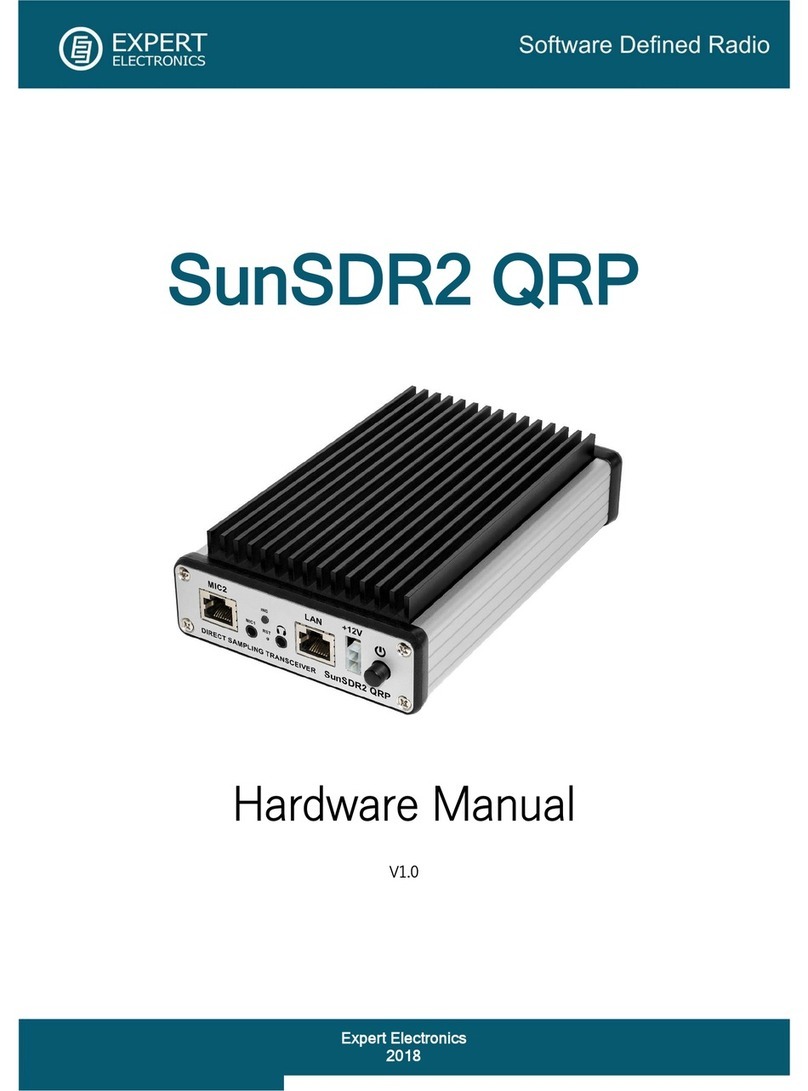
Expert Electronics SunSDR2 QRP User manual

Expert Electronics
Expert Electronics SunSDR2 Pro User manual

Expert Electronics
Expert Electronics SunSDR2 Pro User manual

Expert Electronics
Expert Electronics SunSDR2 DX User manual

Expert Electronics
Expert Electronics DUC/DDC SDR Series User manual

Expert Electronics
Expert Electronics MB1 User manual

Expert Electronics
Expert Electronics MB1 User manual

Expert Electronics
Expert Electronics SunSDR2 DX User manual