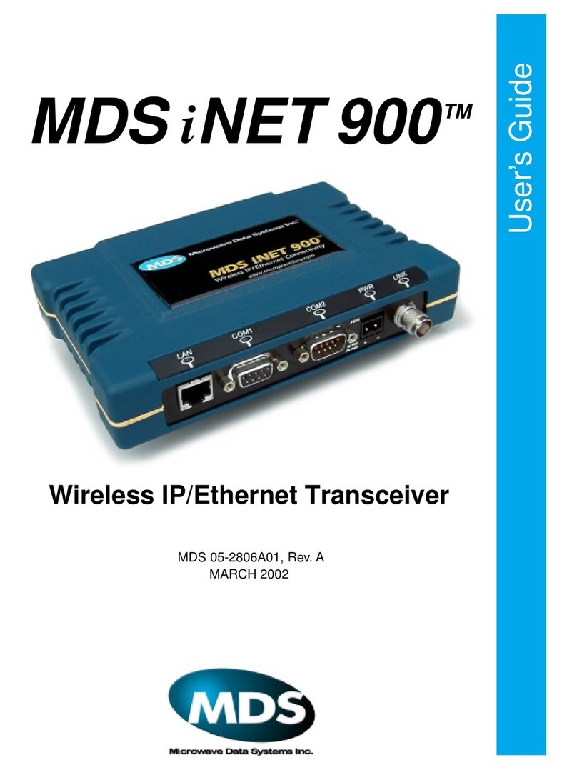
MDS TransNET 900 Operating instructions

Installation and Operation Guide
MDS 05-4055A01, Rev. C
APRIL 2006
900 MHz and 2400 MHz
Extended Range IP Networking Transceivers
Firmware Code 3.0
MDS entraNET™900
MDS entraNET™2400
Microwave Data Systems Inc.
Remote
Access Point

Quick Start Instructions
Listed below are the basic steps for installing MDS entraNET transceivers. Refer to the appro-
priate sections in the manual for detailed information.
1. Initial Checkout
• Set the equipment up in a tabletop arrangement as described in
2 TABLETOP SETUP AND
EVALUATION,(beginning on Page 15)
.
•Follow all steps to ensure proper cable connections and unit configuration. As a minimum, Access
Points must have the following programmed: IP Address, IP Network identifier, and Radio Network
Address. (RF output power and Password should also be reviewed and set if necessary.) Remote
radios normally require only a Radio Network Address to be set. (Note: The Remote Radio Net-
work Address
must
match that of the AP.)
• Connect data equipment to the transceivers. Use LAN/ETH ports for Ethernet systems, or COM2
ports for Serial data systems.
•Verify proper exchange of data communications by viewing the LEDs. The following indications
should be seen on the LED panel within 30 seconds of startup:
PWR
—Lit continuously
LINK
—Lit continuously
ETH
—Lit continuously (unless Sleep is activated)
COM2
—Blinking to indicate exchange of data communications
2. Endpoint Connectivity (PING)Test—for Ethernet Systems Only
•For Ethernet systems, verify the link integrity between the Access Point and endpoint devices con-
nected to Remotes by issuing a
PING
command from the AP. Below is a basic setup diagram for
the PING test. (NOTE: Endpoint devices must have a compatible IP address for this test to work.)
Invisible place holder
3. Set Configuration of AP and Remote Radios
• Refer to
3 AP MANAGEMENT beginning on Page 29
for details on connecting to the AP and
using the built-in menu system. Refer to
4 REMOTE RADIO MANAGEMENT
beginning on
Page 99 for details on programming Remotes.
•If you have a large number of radios to configure, a configuration script may be used to speed the
process. See
USING CONFIGURATION SCRIPTS
beginning on Page 177 for details.
4. Install the Equipment in the Field
•Refer to
6 INSTALLATION beginning on Page 143
for details on site selection, mounting, cabling,
and antenna/feedline recommendations.
• After basic installation, optimize the performance of the radio network following the recommenda-
tions beginning on Page 156.
COM1
ETH PWR
LINK
LAN
PORT
PC RUNNING PING UTILITY ACCESS POINT ETHERNET REMOTE
ETH
PORT
ETHERNET ENDPOINT
(Device Being Pinged)
STRAIGHT THROUGH
CABLE
CROSS-OVER
CABLE
LAN COM1 COM2 PWR LINK

MDS 05-4055A01, Rev. C MDS entraNET System Guide i
Table of Contents
1INTRODUCINGTHE
MDS entraNET SYSTEM. . . . . . . . . . . . . . . . . . . . . . . 1
1.1 ABOUT THIS MANUAL 3
1.2 PRODUCT DESCRIPTION 3
1.3 APPLICATIONS 6
1.4 MDS SECURITY SUITE 10
1.5 ACCESSORIES 12
2TABLETOP SETUP AND
EVALUATION. . . . . . . . . . . . . . . . . . . . . . . . . . . . . . . 15
2.1 INTRODUCTION 17
2.2 CONNECTOR OVERVIEW 17
2.3 TEST SETUP 18
3 AP MANAGEMENT . . . . . . . . . . . . . . . . . . . . . . . . . . 29
3.1 INTRODUCTION 31
3.2 ACCESSING THE MENU SYSTEM 36
3.3 BASIC DEVICE INFORMATION 43
3.4 CONFIGURING NETWORK PARAMETERS 45
3.5 CONFIGURING RADIO PARAMETERS 52
3.6 CONFIGURING THE SERIAL INTERFACES 54

ii MDS entraNET System Guide MDS 05-4055A01, Rev. C
3.7 SECURITY CONFIGURATION 64
3.8 WIRELESS NETWORK MENU 69
3.9 STATISTICS AND EVENT LOG 76
3.10 DEVICE INFORMATION MENU 83
3.11 MAINTENANCE AND TOOLS 84
3.12 REDUNDANCY MENU 92
3.13 DNP3 ROUTING MENU 96
4 REMOTE RADIO
MANAGEMENT . . . . . . . . . . . . . . . . . . . . . . . . . . . . . 99
4.1 INTRODUCTION 101
4.2 Programming Methods 101
4.3 Log-in Procedure 101
4.4 Commands 102
4.5 Minimum Configuration for Remotes 102
4.6 UPGRADING REMOTE FIRMWARE 116
5 SAMPLE
CONFIGURATIONS. . . . . . . . . . . . . . . . . . . . . . . . . 119
5.1 INTRODUCTION 121
6 INSTALLATION . . . . . . . . . . . . . . . . . . . . . . . . . . . . 143
6.1 INSTALLATION 145

MDS 05-4055A01, Rev. C MDS entraNET System Guide iii
6.2 HOW MUCH OUTPUT POWER CAN BE USED?
(U.S.A. and Canada, 900 MHz systems) 152
6.3 HOW MUCH OUTPUT POWER CAN BE USED?
(U.S.A. and Canada, 2400 MHz systems) 153
6.4 HOW MUCH OUTPUT POWER CAN BE USED? (ETSI 2400 MHz systems) 154
6.5 OPTIMIZING PERFORMANCE 156
7TROUBLESHOOTING
AND RADIOTESTS. . . . . . . . . . . . . . . . . . . . . . . . . 161
7.1 TROUBLESHOOTING 163
8TECHNICAL REFERENCE . . . . . . . . . . . . . . . . . . . 173
8.1 UPGRADING AP FIRMWARE 175
8.2 USING CONFIGURATION SCRIPTS 177
8.3 DATA INTERFACE CONNECTORS 183
8.4 TECHNICAL SPECIFICATIONS 185
8.5 dBm-WATTS-VOLTS CONVERSION CHART 189
9 TERMS AND ABBREVIATIONS . . . . . . . . . . . . . . . 191

iv MDS entraNET System Guide MDS 05-4055A01, Rev. C
Copyright Notice
This publication is protected by U.S.A. copyright law. Copyright 2006, Microwave Data Systems, Inc. All rights
reserved.
ISO 9001 Registration
Microwave Data Systems adheres to the internationally-accepted ISO 9001 quality system standard.
Related Materials on the Internet
Data sheets, frequently asked questions, application notes, information on firmware upgrades, and other valuable
information can be found on the MDS Web site at
www.microwavedata.com
.
About Microwave Data Systems Inc.
Over two decades ago, MDS began building radios for business-critical applications. Since then, we’ve installed more
than 500,000 radios in over 110 countries. To succeed, we overcame impassable terrain, brutal operating conditions
and disparate, complex network configurations. We also became experts in wireless communication standards and
system applications worldwide. The result of our efforts is that today, thousands of utilities around the world rely on
MDS-based wireless networks to manage their most critical assets.
The majority of MDS radios deployed since 1985 are still installed and performing within our customers' wireless net-
works. That’s because we design and manufacture our products in-house, according to ISO 9001 which allows us to
control and meet stringent global quality standards.
Thanks to our durable products and comprehensive solutions, MDS is the wireless leader in industrial automation—
including oil and gas production and transportation, water/wastewater treatment, supply and transportation, electric
transmission and distribution and many other utility applications. MDS is also at the forefront of wireless communi-
cations for private and public infrastructure and online transaction processing. Now is an exciting time for MDS and
our customers as we look forward to further demonstrating our abilities in new and emerging markets.
As your wireless needs change you can continue to expect more from MDS. We'll always put the performance of your
network above all. Visit us at
www.microwavedata.com
for more information.
OPERATIONAL & SAFETY NOTICES
CSA/US Notice
The transceiver has been recognized for use in hazardous locations by the Canadian Standards Association
(CSA), which also issues the U.S. mark of approval. The CSA Certification is in accordance with CSA STD
C22.2 No. 213-M1987.
FCC Part 15 Notice
The transceiver complies with Part 15 of the FCC Rules. Operation is subject to the following two conditions: (1) this
device may not cause harmful interference, and (2) this device must accept any interference received, including inter-
ference that may cause undesired operation. This device is specifically designed to be used under Section 15.247 of
the FCC Rules and Regulations. Any unauthorized modification or changes to this device without the express approval
of Microwave Data Systems may void the user’s authority to operate this device. Furthermore, this device is intended
to be used only when installed in accordance with the instructions outlined in this manual. Failure to comply with these
instructions may also void the user’s authority to operate this device.
Manual Revision and Accuracy
While every reasonable effort has been made to ensure the accuracy of this manual, product improvements may result
in minor differences between the manual and the product shipped to you. If you have additional questions or need an
exact specification for a product, please contact our Customer Service Team using the information at the back of this
guide. In addition, manual updates can often be found on the MDS Web site at
www.microwavedata.com
.
U.S. Installations:
Professional installation required. The radio equipment
described in this guide emits radio frequency energy. Although the power level is
low, the concentrated energy from a directional antenna may pose a health hazard.
For 900 MHz units, do not allow people to come closer than 23 cm (9 inches) to
the antenna. For 2.4 GHz units, do not allow people to come closer than 5 cm (2
inches) to the antenna. These distances apply whether the transmitter is operated
in indoor or outdoor environments. More information on RF exposure is available
on the Internet at
www.fcc.gov/oet/info/documents/bulletins
.
ETSI Installations:
In regions where the European Telecommunications Stan-
dards Institute (ETSI) standards apply, 2.4 GHz units with a maximum output
power of 100 mW EIRP are supplied. Do not allow people to come closer than 2.2
cm (1 inch) to the antenna.
RF Exposure
MDS 05-4055A01, Rev. C MDS entraNET System Guide v
Environmental Information
The manufacture of this equipment has required the extraction and use of natural resources. Improper disposal may
contaminate the environment and present a health risk due to hazardous substances contained within. To avoid dissem-
ination of these substances into our environment, and to limit the demand on natural resources, we encourage you to
use the appropriate recycling systems for disposal. These systems will reuse or recycle most of the materials found in
this equipment in a sound way. Please contact MDS or your supplier for more information on the proper disposal of
this equipment.

vi MDS entraNET System Guide MDS 05-4055A01, Rev. C
LAN COM1 COM2 PWR LINK

MDS 05-4055A01, Rev. C MDS entraNET System Guide 1
1
INTRODUCING THE
MDS entraNET SYSTEM
1 Chapter Counter Reset Paragraph
1.1 ABOUT THIS MANUAL 3
1.1.1 Supplemental Information Online ..................................................3
1.2 PRODUCT DESCRIPTION 3
1.2.1 Model Offerings .............................................................................6
1.3 APPLICATIONS 6
1.3.1 Long-Range Wireless LAN ............................................................6
Antenna Placement ............................................................................6
Communication Rules ........................................................................7
1.3.2 Combining Serial and IP or Ethernet Devices ...............................7
1.3.3 DNP3 Protocol-Aware Networks ...................................................8
1.3.4 Upgrading an Older Wireless Network with Serial Interfaces ........9
Replacing Legacy Wireless Products .................................................9
Supplementing a Legacy Wireless Network with IP services ...........10
1.3.5 Protected Network (Redundant) Configuration ...........................10
1.4 MDS SECURITY SUITE 10
1.4.1 Intrusion Detection via SNMP Traps ............................................12
1.5 ACCESSORIES 12
LAN COM1 COM2 PWR LINK

2 MDS entraNET System Guide MDS 05-4055A01, Rev. C
LAN COM1 COM2 PWR LINK

MDS 05-4055A01, Rev. C MDS entraNET System Guide 3
1.1 ABOUTTHIS MANUAL
This guide provides installation and operating instructions for the MDS
entraNET 900
TM
and MDS entraNET 2400
TM
series radio system. The
guide is intended for use by those who install, configure, and operate the
entraNET wireless network.
Quick Start
instructions are provided on the inside front cover of this
guide. They provide the basic steps for installing and operating the
transceivers, but do not cover all of the configurable parameters. The
main section of this guide contains complete information on menu func-
tions, as well as detailed installation, operation, and troubleshooting
information. This guide is arranged into the following eight chapters:
• Chapter 1—
Introducing the MDS entraNET System
(Page 1)
• Chapter 2—
Tabletop Setup and Evaluation
(Page 15)
• Chapter 3—
Access Point (AP) Management
(Page 29)
• Chapter 4—
Remote Radio Management (Page 99)
• Chapter 5—Sample Configurations (Page 119)
• Chapter 6—Installation (Page 143)
• Chapter 7—Troubleshooting and Radio Tests (Page 161)
• Chapter 8—Technical Reference (Page 173)
• Chapter 9—Terms and Abbreviations (Page 191). Terms
defined in Chapter 9 are italicized on first appearance.
1.1.1 Supplemental Information Online
Release notes, manual updates, and other supplemental materials are
available online for many MDS products. For more information, visit us
at online at www.microwavedata.com.
1.2 PRODUCT DESCRIPTION
The entraNET system is an easy-to-install wireless solution supporting
long-range serial and Ethernet data transmission at speeds up to
106 kbps. The system includes an Access Point (AP) transceiver and a
Remote transceiver capable of serial and Ethernet communication.
These radios serve a variety of network configurations. Figure 1-1
shows the two radios.

4 MDS entraNET System Guide MDS 05-4055A01, Rev. C
Invisible place holder
Figure 1-1. MDS entraNET Transceiver Models
Robust Radio
Operation MDS entraNET transceivers use an advanced Media Access Controller
(MAC) to ensure network access for stations with data to send. The
MAC permits data to be sent from endpoint devices on an on-demand
basis, preventing over-the-air data collisions and ensuring that data gets
through as intended. MAC functionality eliminates the need for active
polling of Remotes, a key requirement in Report-by-Exception (RBE)
applications.
Rugged Packaging MDS entraNET radios are housed in compact and rugged die-cast cases
that need only be protected from direct exposure to the weather. The
transceiversaresuppliedwith flatsurface-mounting bracketsoroptional
35mm DIN rail brackets, depending on customer requirements.
Simple Installation Basic installation typically employs an omni-directional antenna at the
AP site and a directional antenna at each associated Remote site. The
antenna is a vital link in the system and must be chosen and installed
correctly. INSTALLATION on Page 145 provides guidance on choosing
proper antennas and installation sites.
To establish basic service, connect an antenna, connect an Ethernet
LAN (Local Area Network) to the AP, connect a serial or Ethernet
device to the Remotes, apply power, set a few operating parameters via
a personal computer, and you are done. No license is required for oper-
ation in the U.S.A., Canada, and many other countries. Check the regu-
lations in your country before placing the radios on the air.
MDS Security Suite Network security is a vital issue in today’s wireless world. The
MDS entraNET system provides multiple tools to help you build a net-
work that minimizes the risk of eavesdropping or unauthorized access.
Some security features are inherent to radio operation, such as the use of
spread-spectrum transmission; other techniques are built into the radio
Access Point
Remote

MDS 05-4055A01, Rev. C MDS entraNET System Guide 5
firmware, including data encryption, enabling or disabling remote
access channels, and password protection.
Remember, security is not a one-step process that can be simply turned
on and forgotten. It must be practiced and enforced at multiple levels,
every day. Section 1.4 contains additional information about entraNET
security features.
License-Free
Operation The transceivers are designed for frequency-hopping spread-spectrum
operation in the license-free 900 MHz or 2400 MHz band. They can pro-
vide reliable long distance communications over line-of-sight signal
paths.
Multiple Services Networks can include a mixture of equipment requiring Ethernet and
serial data interfaces on the same cell or AP. This flexibility allows the
transceiver to provide services in data networks that are on a migration
path from legacy serial or EIA-232-based hardware to faster and more
easily interfaced Ethernet systems.
Flexible
Management Configuration, troubleshooting and other management activities are per-
formed using a connected PC, locally or remotely. Modes of access
include a local RS-232 console, local or remote IP access through
Ethernet, Telnet, or a Web browser, and Simple Network Management
Protocol (SNMP).
Feature Summary The MDS entraNET design makes installation and configuration an
easy task, while allowing for configuration changes in the future.
•Long-range transmission over favorable, unobstructed terrain, with
sufficient antenna heights
• Low power consumption—Sleep and Shutdown modes to enable
solar-powered operation
• Repeater configurations—A repeater scheme can be established to
extend the transmission range or to work around obstructions in a
network. This is accomplished by connecting two radios back to
back at a single site.
• Industrial-grade product—Extended temperature range for trou-
ble-free operation in extreme environments
• Robust radio communications—Designed to perform in high-inter-
ference environments
•MDS Security Suite—Blocks common attack schemes and prevents
“rogue” hardware from gaining access to or control of a network.
Common attack events are logged and reported via alarms.
• Fast, 106 kbps data speed—Ten times faster than 9.6 kbps radios
• Simple setup—Ethernet bridge configuration option requires mini-
mal setup
•Serial ports—Gateway for serial interface equipment to IP or Ether-
net networks with an embedded terminal server

6 MDS entraNET System Guide MDS 05-4055A01, Rev. C
1.2.1 Model Offerings
The MDS entraNET system includes two primary radio types— APs
and Remotes. Table 1-1 summarizes the interface capabilities for each
entraNET radio type.
NOTE: A Remote serves only one endpoint MAC address, even if a
bridge or hub is used.
1.3 APPLICATIONS
The following sections describe typical entraNET installations. All
installations should be reviewed by a network manager to ensure proper
integration with existing equipment.
1.3.1 Long-Range Wireless LAN
The wireless LAN is a common application of the entraNET system. It
consists of a central control station (AP) and one or more associated
Remote radios, as shown in Figure 1-2 on Page 7. A LAN provides
communications between a central LAN/WAN and remote Ethernet
endpoints. Remote radios can support one Ethernet endpoint each.
The operation of the radio system is transparent to the computer equip-
ment connected to it. As such, the system behaves just as it would in a
hardwired arrangement, with respect to data format and integrity.
Over-the-air messages are exchanged at the Ethernet level, including all
types of IP traffic.
Antenna Placement
The AP antenna is positioned at a location from which it can reliably
communicate with all of the Remote radios in the system. Commonly,
this is a relatively high location on top of a building, communications
tower or other elevated point.
Communication Rules
•ARemote transceiver can only talk over-the-air to an AP.
•Peer-to-peer communications between Remotes can take place indi-
rectly through the AP.
• An AP can only talk over-the-air to Remote radios; however, two
APs can communicate with each other through their Ethernet con-
nectors when a wired LAN/WAN is utilized.
Table 1-1. MDS entraNET Models and Data Interface Services
Model LAN/ETH COM1*COM2
AP LAN Yes Yes
Remote ETH Yes Yes
NOTES
*This connector provides access to the radio menu system.

MDS 05-4055A01, Rev. C MDS entraNET System Guide 7
Invisible place holder
Figure 1-2. Typical Wireless LAN System
1.3.2 Combining Serial and Ethernet Devices
Prior to the introduction of the entraNET series, multiple networks were
often needed to service different types of communication protocols. An
entraNET system provides this functionality through a single AP radio.
Each of the Remote radios in a system can be connected via IP to dif-
ferent SCADA or telemetry hosts, transporting different (or the same)
protocols. Both data streams are completely independent, and the trans-
ceiver provides seamless, simultaneous operation, as shown in
Figure 1-3.
Invisible place holder
Figure 1-3. Multiple Protocol Network
By using a single AP, the cost of infrastructure deployment is cut in half,
with only one antenna, one feedline, and one lightning protector
required. Other cost reductions come from the system as a whole,
Remote
Remote
Access Point
Remote
Remote
WAN/LAN
Ethernet
Device
Ethernet
Device
LINKETHCOM1PWR
LINKETHCOM1PWR
Ethernet
Device
LINKETHCOM1PWR
LINKETHCOM1PWR
Ethernet
Device
LANCOM1COM2PWRLINK
PC Running
NetView SCADA Host
Total Flow
Access Point
Re ote
SCADA Host
Modbus/IP
Serial Polling
Converter
Re ote
Re ote
RTU
EIA-232
EIA-232
TCP/IP
C
O
M
2P
W
R
L
I
N
KC
O
M
1
C
O
M
2P
W
R
L
I
N
KC
O
M
1
C
O
M
2P
W
R
L
I
N
KC
O
M
1
HUB
Serial
Device
HUB
HUB
WAN
Ethernet
Device
ROUTER
HUB
LANCOM1COM2PWRLINK

8 MDS entraNET System Guide MDS 05-4055A01, Rev. C
including reduced management requirements when using
MDS NETview Management System (MS) software. In addition,
entraNET offers nearly unlimited potential for future applications that
run over IP and Ethernet services.
Inan IP-to-serialscenario,every Remoteissent informationreceived by
the AP Ethernet port. Likewise, information received at the Remote
serial port is transmitted to the AP, and the AP delivers this information
through its Ethernet port in the form of an IP packet.
Additionally, the AP serial port can be used as a virtual Remote. This
means that encapsulated serial information received by the AP is sent
out the serial port of all Remotes as well as the AP serial port. The
reverse is also true, meaning that data received by the serial port of any
Remote or the AP serial port is encapsulated and sent out the AP
Ethernet port.
This arrangement can be used to connect an endpoint device at a
Repeater site without the need for an additional Remote radio.
1.3.3 DNP3 Protocol-Aware Networks
The MDS implementation of Distributed Network Protocol 3 (DNP3)
allows the transfer and routing of DNP3 messages between serial
devices, while also supporting the conversion to an IP Ethernet network.
As DNP3 messages are routed through the system, the APs “learn” the
locations of all end devices, regardless of whether they are configured
for serial or Ethernet communication, eliminating the need to configure
their individual locations.
DNP3 devices with an Ethernet or IP interface can be connected to a
transceiver in one of two ways:
• To the Ethernet port of an AP radio
• To the Ethernet port of a Remote radio
DNP3 devices with a serial RS-232 interface can be connected to a
transceiver in one of two ways:
• To the serial port of an AP radio
• To the serial port of a Remote radio
The capability for DNP3 message routing is optional for the transceiver.
An Authorization Key is required to enable this functionality, and is
available for purchase from MDS.
NOTE: Detailed information on the DNP3 protocol is available on the
DNP Users’ Group Web site at www.dnp.org.

MDS 05-4055A01, Rev. C MDS entraNET System Guide 9
1.3.4 Upgrading an Older Wireless Network with
Serial Interfaces
Millions of wireless data products have been sold in the last two decades
for licensed and license-free operation, many of them manufactured by
MicrowaveData Systems.Thereare severalwaysthat thesesystems can
benefit from employing MDS entraNET wireless equipment, including
flexible serial and Ethernet interfaces, higher data throughput, and ease
of installation.
MDS entraNET radios are well suited to replace leased lines, dial-up
lines, or existing data radios by taking advantage of the built-in serial
and Ethernet interfaces on the transceiver. The sections below discuss
two common scenarios.
Replacing Legacy Wireless Products
In most cases, legacy radio transceivers supporting serial interface
equipment can be replaced with MDS entraNET radios with little or no
special configuration. This equipment can be connected to MDS
entraNET radios through the COM1 orCOM2 port with a DB-25 to RJ-45
cable wired for EIA-232 signaling. The COM2 port supports standard
EIA-232 signaling and acts as a data communications equipment (DCE)
device.
NOTE: Several previous MDS-brand products contained signal lines
on their interface connectors that are not used or required on
entraNET radios. Consult the equipment manual(s) for inter-
face pinout information, and connect only the required pins.
Supplementing a Legacy Wireless Network with IP Services
MDS entraNET Remotes support most polled protocols. The serial
interfacesencapsulate serialdata intwo differentmodes: connectionless
(User Datagram Protocol, or UDP) and connection-oriented (Transmis-
sion Control Protocol, or TCP).
For complete details on serial gateway interface modes, see “CONFIG-
URING THE SERIAL INTERFACES” on Page 54.
1.3.5 P22 Protected Network (Redundant)
Configuration
For mission-critical applications, MDS offers the Protected Network
Station. This radio incorporates two entraNET AP transceivers, two
power supplies, and a switchover logic board that automatically selects
betweenTransceiver Aand TransceiverB astheactive radio.Figure 1-4
shows a view of the protected chassis. For system-level information on
this product, see MDS publication 05-4161A01.

10 MDS entraNET System Guide MDS 05-4055A01, Rev. C
Invisible place holder
Figure 1-4. MDS P22 Protected Network Station
(incorporates two MDS entraNET APs)
1.4 MDS SECURITY SUITE
Today, the operation and management of an enterprise is becoming
increasingly dependent on electronic information flow. An accompa-
nyingconcernbecomesthe securityof thecommunicationinfrastructure
and the security of the data itself.
The MDS entraNET is capable of dealing with many common security
issues. Table 1-2 profiles security risks and how the MDS entraNET
provides a solution for minimizing vulnerability.
Table 1-2. Security Risk Management
Security Risk The MDS entraNET Solution
Unauthorized access to the backbone
network through a foreign remote radio
Approved Remotes List
Only radios on the Approved
Remotes list connect
“Rogue” AP, where a foreign AP takes
control of some or all Remote radios and
thus remote devices
Approved AP List
A Remote connects only to APs on
its Approved AP List
“Dictionary attacks”, where an intruder
runs a program that sequentially tries to
break a password
Failed log-in lockdown
After three tries, a transceiver
ignores log-in requests for five
minutes. Critical event reports
(traps) are generated as well.
Denial of service, where Remote radios
could be reconfigured with bad
parameters, bringing the network down
Remote log-in
Local console log-in
HTTP (Hypertext Transfer
Protocol) and Telnet disabled,
enabling only local management
services

MDS 05-4055A01, Rev. C MDS entraNET System Guide 11
1.4.1 Intrusion Detection via SNMP Traps
In addition to the operative tools and techniques, the entraNET system
provides an SNMP-based network management system with traps
(alarms) that report suspicious activities or events. These include:
• Log-in attempt limit exceeded (accessed via HTTP)
• Successful log-in or logout (accessed via HTTP)
Airsnort and other war-driving intruders in
parking lots, near buildings, etc.
Frequency-hopping spread
spectrum (FHSS) does not talk
over the air with standard 802.11b
cards
The transceiver cannot be put in a
“promiscuous” mode
Proprietary data framing
Eavesdropping, intercepting messages 128-bit encryption
Key cracking Automatic Key Rotation algorithm.
In addition, a Force Key Rotation
command is available to
immediately rotate the keys of the
AP and synchronize all Remotes
with it.
Replaying messages 128-bit encryption with rotating
keys
Unprotected access to configuration via
SNMP
Non-secure SNMP versions can be
enabled or disabled at will.
SNMPv3 password protection
Potential, ongoing attacks Provides early warning via SNMP
through critical event reports of
unauthorized log-in attempts and
suspicious activities
Table 1-2. Security Risk Management
Security Risk The MDS entraNET Solution

12 MDS entraNET System Guide MDS 05-4055A01, Rev. C
1.5 ACCESSORIES
MDS entraNET transceivers may be used with one or more of the acces-
sories listed in Table 1-3. Contact MDS for ordering details.
Table 1-3. Accessories
Accessory Description MDS Part No.
AC Power
Adapter Kit
A small power supply module designed for
continuous service. UL approved. Input:
120/220; Output: 13.8 Vdc at 2.5 A
01-3682A02
Omni-
Directional
Antennas
Rugged antennas well suited for use at AP
installations. Ask your MDS Sales
Representative for details.
Contact MDS
Yagi Antenna
(Directional)
Rugged antennas well suited for use at Remote
installations. Ask your MDS Sales
Representative for details.
Contact MDS
TNC Male-to-N
FemaleAdapter
One-piece RF adaptor plug. 97-1677A161
TNC Male-to-N
FemaleAdapter
Cable
Short length of coaxial cable used to connect
the TNC antenna connector to a Type N
connector commonly used on large-diameter
coaxial cables.
97-1677A159
(3 ft./1m)
97-1677A160
(6 ft./1.8m)
2-Pin Power
Plug
Mates with power connector on the transceiver.
Screw terminals are provided for wires; locking
screws are threaded to prevent accidental
disconnection.
73-1194A39
Ethernet RJ-45
Straight-thru
Cable (CAT5)
Cable assembly normally used to connect an
Ethernet device or LAN to the transceiver. Both
ends of the cable are wired identically.
(Cable length ≈3 ft./1m)
97-1870A20
Ethernet RJ-45
Crossover
Cable (CAT5)
Cable assembly used to connect an AP to an
Ethernet endpoint. (Cable length ≈3 ft./1m)
97-1870A21
RJ-12 to DB-9
Female Adapter
Allows access to Data Serial port COM1 on
Remotes or APs.
73-2434A02
RJ-45 to DB-9
Female Adapter
Allows access to Data Serial port COM2 on
Remotes or APs.
73-2434A12
EIA-232
Shielded Data
Cable
Shielded cable terminated with a DB-9 male
connector on one end, and a DB-9 female on
the other end; 6 ft./1.8m long.
97-1971A03
Fuse Small, board-mounted fuse used to protect
against overcurrent conditions.
29-1784A03
Other manuals for TransNET 900
1
This manual suits for next models
3
Table of contents
Other MDS Transceiver manuals

MDS
MDS 4710B Operating instructions

MDS
MDS EL705 OEM Series Operating instructions

MDS
MDS 4710A Operating instructions

MDS
MDS iNET 900 Series User manual

MDS
MDS MDS iNET-II 900 User manual

MDS
MDS TransNET 900 Original operating instructions

MDS
MDS MDS 4710 Series Operating instructions

MDS
MDS iNET 900 Series User manual

MDS
MDS iNET 900 Series User manual

MDS
MDS 2710D Original operating instructions