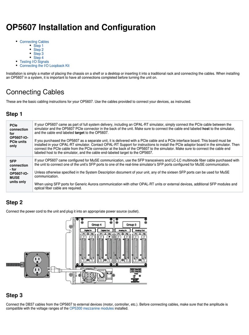
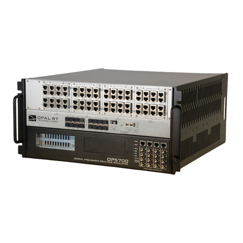
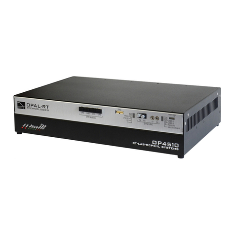
Opal-RT OP5707XG Operating and maintenance instructions

OP5707XG Installation and Configuration
Connecting the Ground Screw
Connecting Network Cables
Connecting the I/O Loopback Kit
Connecting the Synchronization Cable
Connecting the USB Cable
Connecting the Ground Screw
Connecting Network Cables
Connecting the I/O Loopback Kit
Connecting the Synchronization Cable
Connecting the USB Cable
Follow this simple installation procedure. Make sure to respect proper grounding,
1. Place the OP5707XG on a shelf, desktop, or install in a traditional rack
2. Connect the power cable to the nearest power outlet
3. Connect the ground screw as described in the “CONNECTING THE GROUND SCREW” section
4. Connect the blue RJ45 cable to the Ethernet port on the OP5707XG and connect to the same network used by the host PC.
OPAL-RT strongly recommends the use of anti-static wrist straps whenever handling any electronic device provided by OPAL-RT.
Disconnect power before servicing.
OPAL-RT simulators and hardware devices may be subjected to electromagnetic interference (EMI) when installed in proximity to
other devices. Make sure to connect the ground to the rack or strong earth to prevent any EMI related damage to the simulator.
Connecting the Ground Screw
You must connect a grounding cable from the OP5707XG ground screw to ensure that it terminates securely in a ground. Proper grounding helps to
prevent electric shocks, protects the OP5707XG from voltage spikes (from a variety of causes, including lightning strikes), and provides increased
immunity from EMI by lowering noise levels and emissions.
Select a flat braided grounding strap of adequate length (as short as possible provides the best protection), with ring terminals on each end.
Attach one ring terminal to the ground screw on the OP5707XG (shown in the figure below).
Attach the other ring terminal to the rack using a nut and lock washer.

Connecting Network Cables
The network cable must only be connected to the standard computer connector network jack. DO NOT connect the network cable in any jack other than
the jack intended for that purpose.
See the System Integration document delivered with the system for information about the active port.
Connecting the I/O Loopback Kit
Note: The following procedure is only used for test purposes when no external source is available.
The loopback kit included in the starter kit allows users to test system signals. The connection is made easy with a custom flat cable that matches OPAL-
RT standard DB37 pin assignments.
Connect one end of the flat cable to the loopback board
Connect the loopback board to the simulator DB37 Output signal
Connect the other end (DB37 connector) of the flat cable to the simulator DB37 Input signal
Connect the VUser (required to preserve isolation) from the loopback board to the OP5707XG

Note: Although some boards do provide a power source, using that would compromise the isolation. OPAL-RT recommends using external power
source: the user must connect the power wires (provided) to either a 5 or 12 V power source. Make sure that the Vuser source switch on the
loopback board is set to “External”.
The breakout board provided allows users to access each pin of the DB37 separately through the screw terminals. Simply insert the breakout board DB37
connector onto the desired DB37 connector on the simulator.
Refer to the system description document or the user manual of the installed in the system for exact pin assignments.OP5300 Mezzanine Modules
Connecting the Synchronization Cable
The OP5700 offers two synchronization options: via optical fiber (recommended) or via legacy copper cable.

The synchronization link must be daisy-chained between all chassis participating in the simulation. The system which is configured to be the Master of the
synchronization in the RT-LAB or HYPERSIM software is the head of the daisy-chain, and the synchronization cable must be connected in the TX output
of this system.
The other end must be connected to the RX input of the second system to be synchronized (configured as Slave in the software). If there are more than
two systems to synchronize, another cable must be installed between the TX output of the second system and the RX input of the third system, etc. until
the last system.
The figure below shows the connection via optical fiber :
Note: Synchronization cables are not required between an OP5707 and remote I/O chassis connected via MuSE since the synchronization link is
integrated into the MuSe link.
Connecting the USB Cable
The USB(A)-USB(B) cable is required only to reprogram the FPGA using the JTAG port when programming has been lost or damaged. Contact
Technical Support for all FPGA programming issues.
Connect one end to a Windows PC USB port and the other end to the USB JTAG port on the OPAL-RT simulator, then follow the technical support
representative’s instructions to reprogram the FPGA.
Connecting the Ground Screw
Connecting Network Cables
Connecting the I/O Loopback Kit

Connecting the Synchronization Cable
Connecting the USB Cable
Connecting the Ground Screw
Connecting Network Cables
Connecting the I/O Loopback Kit
Connecting the Synchronization Cable
Connecting the USB Cable
Follow this simple installation procedure. Make sure to respect proper grounding,
1. Place the OP5707XG on a shelf, desktop, or install in a traditional rack
2. Connect the power cable to the nearest power outlet
3. Connect the ground screw as described in the “CONNECTING THE GROUND SCREW” section
4. Connect the blue RJ45 cable to the Ethernet port on the OP5707XG and connect to the same network used by the host PC.
OPAL-RT strongly recommends the use of anti-static wrist straps whenever handling any electronic device provided by OPAL-RT.
Disconnect power before servicing.
OPAL-RT simulators and hardware devices may be subjected to electromagnetic interference (EMI) when installed in proximity to
other devices. Make sure to connect the ground to the rack or strong earth to prevent any EMI related damage to the simulator.
Connecting the Ground Screw
You must connect a grounding cable from the OP5707XG ground screw to ensure that it terminates securely in a ground. Proper grounding helps to
prevent electric shocks, protects the OP5707XG from voltage spikes (from a variety of causes, including lightning strikes), and provides increased
immunity from EMI by lowering noise levels and emissions.
Select a flat braided grounding strap of adequate length (as short as possible provides the best protection), with ring terminals on each end.
Attach one ring terminal to the ground screw on the OP5707XG (shown in the figure below).
Attach the other ring terminal to the rack using a nut and lock washer.
Connecting Network Cables

The network cable must only be connected to the standard computer connector network jack. DO NOT connect the network cable in any jack other than
the jack intended for that purpose.
See the System Integration document delivered with the system for information about the active port.
Connecting the I/O Loopback Kit
Note: The following procedure is only used for test purposes when no external source is available.
The loopback kit included in the starter kit allows users to test system signals. The connection is made easy with a custom flat cable that matches OPAL-
RT standard DB37 pin assignments.
Connect one end of the flat cable to the loopback board
Connect the loopback board to the simulator DB37 Output signal
Connect the other end (DB37 connector) of the flat cable to the simulator DB37 Input signal
Connect the VUser (required to preserve isolation) from the loopback board to the OP5707XG

Note: Although some boards do provide a power source, using that would compromise the isolation. OPAL-RT recommends using external power
source: the user must connect the power wires (provided) to either a 5 or 12 V power source. Make sure that the Vuser source switch on the
loopback board is set to “External”.
The breakout board provided allows users to access each pin of the DB37 separately through the screw terminals. Simply insert the breakout board DB37
connector onto the desired DB37 connector on the simulator.
Refer to the system description document or the user manual of the installed in the system for exact pin assignments.OP5300 Mezzanine Modules
Connecting the Synchronization Cable
The OP5700 offers two synchronization options: via optical fiber (recommended) or via legacy copper cable.
The synchronization link must be daisy-chained between all chassis participating in the simulation. The system which is configured to be the Master of the
synchronization in the RT-LAB or HYPERSIM software is the head of the daisy-chain, and the synchronization cable must be connected in the TX output
of this system.
The other end must be connected to the RX input of the second system to be synchronized (configured as Slave in the software). If there are more than
two systems to synchronize, another cable must be installed between the TX output of the second system and the RX input of the third system, etc. until
the last system.
The figure below shows the connection via optical fiber :
Note: Synchronization cables are not required between an OP5707 and remote I/O chassis connected via MuSE since the synchronization link is
integrated into the MuSe link.

Connecting the USB Cable
The USB(A)-USB(B) cable is required only to reprogram the FPGA using the JTAG port when programming has been lost or damaged. Contact
Technical Support for all FPGA programming issues.
Connect one end to a Windows PC USB port and the other end to the USB JTAG port on the OPAL-RT simulator, then follow the technical support
representative’s instructions to reprogram the FPGA.
Table of contents
Other Opal-RT Computer Hardware manuals
Popular Computer Hardware manuals by other brands

Intel
Intel Xeon E5-2400 Thermal/Mechanical Design Guide

NTI
NTI DVI-EDID-EMLTR-LC instruction manual

Alphacool
Alphacool Core Flat Reservoir Series installation instructions

Actions Microelectronic
Actions Microelectronic EZCast quick start guide

Digital Equipment
Digital Equipment VAXft owner's manual

RME Audio
RME Audio AEB4/8-1 user guide

ISE Fleet Services
ISE Fleet Services A317 installation guide

Avalue Technology
Avalue Technology ECM-EHL3 user manual

Sony
Sony BKDS-2530 Operation manual

National Instruments
National Instruments PXIe-5832 Getting started

Nakayo
Nakayo NYC-16VDSL-B Instruction & installation manual

Tone Commander
Tone Commander 6030X installation instructions