Opel 1900 User manual

I
GROUP 3
SUSPENSION
AND
STEERING I
Section
Title
Page No
3A
Front Suspension
. . . . . . . . . .
3A- 2
3B
Steering Linkages
38-l 9
3C
Front End Alignment 3C-22
3D Steering Gear
.._........
3D-27
Steering Column
3E 1900
-
Manta
,._________...
3E-35
GT
. . . . . . . . . . . . . . . . . . . . . . . . . . . . . . . . . . . .
3E-42
3F
Rear Suspension
. . . . . . . . .
3F-51
3G Wheels
and Tires
. . . . . . . . . .
36-55
cardiagn.com

3A- 2 1973 OPEL SERVICE MANUAL
FRONT SUSPENSION
CONTENTS
Subject
DESCRIPTION AND OPERATION:
Suspension
Description
. . . . . . . . . . . . . . . . . . . . . . . . . . . . . . . . . . . . . . . . . . . . . . . . . . . .
DIAGNOSIS: (Not Applicable)
MAINTENANCE AND ADJUSTMENTS:
Front Wheel
Bearing
Adjustments
. . . . . . . . . . . . . . . . . . . . . . . . . . . . . .
MAJOR REPAIR:
Removal and Installation of Front Suspension . . . . . . . .
Upper Ball Joint Removal and Installation
. . . . . . . . . . . . . .
Lower Ball Joint Removal and Installation
. . . . . . . . . . . . . .
Upper Control Arm Removal and Installation
. . . . . . . . . .
Lower Control Arm Removal and Installation
. . . . . . . .
Steering
Knuckle Removal and
Installation
. . . . . . . . . . . . . .
Shock Absorber
Removal and
Installation
. . . . . . . . . . . . . . . .
Front Spring Removal and Installation
. . . . . . . . . . . . . . . . . . . . . .
SPECIFICATIONS:
Page No.
3A-
2
3A-
4
3A-
4
3A-
7
3A-
7
3A-10
3A-11
3A-13
3A-15
3A-15
Bolt Torque and Front End Alignment Specifications
. . . . . . . . . . . . . . . . . . . . . . . . . . . . . . . . . . . . . . . . . . . . . . . . . . . . . . . . . . . . . . . . . . . . . . . . . . . . . . . . . . . . . . . . . . . . . . . . . .
3A-18
DESCRIPTION AND OPERATION
SUSPENSION DESCRIPTION
GT
The GT uses a maintenance-free independent front
wheel suspension and features unequal length con-
trol arms and a transverse three-leaf spring. The en-
tire front suspension is attached to the front cross
member and can be removed as a unit if so desired.
The engines installed in the GT are not supported by
mounting brackets but rest on a separate cross mem-
ber. The front suspension cross member is reinforced
in the area of the attachment to the frame. A one-
part damper plate is installed between cross member
and frame.
Ball joints are employed in the conventional manner
to provide pivoting joints between the control arms
and steering knuckles. Upward movement of the
control arms is limited by two large rubber bumpers
attached to the cross member.
Road shock is dampened by the double direct acting
shock absorbers and a transverse double or triple
steel band spring. In addition, the shock absorber
limits downward travel of the control arms.
All moving parts, including ball joints, have no need
for lubrication as they have been pre-lubricated for
the life of the vehicle.
For distinguishing the individual front suspension
cross members,.a red label with black letters is stuck
onto the front side of the shock absorber support. See
Figure 3A-3.
Opel
1900. Manta
The front wheel suspension has coil springs and con-
trol arms of different length.
The stabilizer is designed to act as a tie strut. The end
is supported in a rubber bushing which is located in
a piece of tubing welded into the longer control arm.
To minimize brake torque, the horizontal shafts of
cardiagn.com

FRONT SUSPENSION 3A- 3
4RM
“PPtR
BALL
SHOCK ABSORBER
UPPER CONTROL,
UPPER CONTROL
ARM SHAFT
“:,‘,:“,‘,“,“,
,“pd,,‘,
T
/RUBBER BUMPER
\
CROSSMEMBER
ROTOR
/
LOWER BALL JOINT FRONT SPRING
Figure 3A-2 GT Front Suspension (Disc Brakes)
the upper and lower control arm are not in parallel
(anti- dive).
The lower control arm is connected to the steering
knuckle with a ball joint.
3A-4
Figure 3A-3 Cross Member Marking Figure 3A-4 Front Suspension
-
Opel 1900 Manta
cardiagn.com

3A- 4 1973 OPEL SERVICE MANUAL
The two cross-members to body supports are at-
tached to the horizontal part of the cross-member
with two bolts. The
oufererbolt
serves simultaneously
as support for the lower control arm. As the bolt is
inserted from the front, the cross-member to body
support can be removed without the lower control
arm. The inner bolt attaches simultaneously to the
steering.
The stabilizer is U-shaped and supported in rubber
bushings in the two cross-members to body supports.
The complete front suspension is attached to the
underbody in four places.
The engine damper blocks are bolted to the inside of
the inclined parts of the cross-member.
The front wheel bearings are roller bearings.
All front suspension joints are maintenance-free.
MAINTENANCE AND ADJUSTMENTS
FRONT WHEEL BEARING ADJUSTMENT
1. If wheel has not previously been removed from the
car, remove grease cap, cotter pin, and spindle nut.
Discard cotter pin.
2. Torque spindle nut to 18
lb.ft.
while rotating
wheel. This will allow the bearings to settle.
3. Back offspindle nut
l/4
turn. If slot and cotter pin
hole are staggered, further back off nut
l/l2
turn,
but do not tighten, until next slot in nut is in align-
ment with hole in spindle. Install new cotter pin. A
properly adjusted wheel bearing has a small amount
of end play and a loose nut when adjusted in the
above manner.
MAJOR REPAIR
REMOVAL AND INSTALLATION OF FRONT
SUSPENSION
(COMPLETE ASSEMBLY)
Removal GT
1. Prior to raising front end of car, apply parking
brake and block rear wheels.
2. Raise front end of car with a jack. It is recom-
mended that a wood block be placed between the
jack and the front cross member to prevent damage
to the cross member.
3. Support front end of car by placing floor stands
unde:r jacking brackets.
4. Support engine-transmission assembly in upper-
most position with jack stand at rear of engine, or an
alternate method would be to use Engine Holding
Fixture, Tool J-23375. See Figure 3A-5.
Install tool by removing upper kngine mount nut and
installing fixture. Replace nut and tighten. The en-
gine will now be supported by the tool between the
frame rails.
Figure
3A-5
Engine Holding Fixture Installed
5. Loosen steering mast at the lower universal joint
and take out clamp bolt. Loosen clamp at the upper
universal joint and lift steering mast upwards until it
is free at the lower universal joint. See Figure
3A-6.
6. Disconnect brake lines at brake hose.
7. Disconnect shock absorber at upper mounting. It
is necessary to remove air cleaner. See Figure
3A-24.
8. Disconnect engine mounts at cross member.
9. Remove front suspension cross member attaching
nuts and lower the cross member.
Removal Opel 1900
-
Manta
1. Prior to raising front end of car, apply parking
brake and block rear wheels.
cardiagn.com

FRONT SUSPENSION 3A- 5
Figure
3A-6
GT Steering Mast Joint
2. Install Hooks J-23697 before jacking up car to
assure proper loading of suspension bushings and
mounts. See Figure
3A-7.
3. Raise front of vehicle and support with stands.
4. Remove front wheels.
5. Remove guard plate. See Figure
3A-8,
6. Remove brake line retainers on both sides. The
brake system remains closed. Unscrew brake calipers
and suspend them in wheel house.
Figure
3A-9
Removing Guard Plate
7. Suspend engine with a suitable engine lifter, simi-
lar to the one shown in Figure
3A-9.
8. Unscrew lower steering mast clamp bolt out of
pinion flange. See Figure
3A-
10.
9. Unscrew front left and right engine mount from
damper block.
10. On top and in the rear, unscrew front suspension
Figure
3A-7
Installing Hooks J-23697 Figure
3A-9
Suitable Engine
Liftel
cardiagn.com

3A- 6 1973 OPEL SERVICE MANUAL
Figure 3A-10 Steering Mast Clamp Bolt
assembly at the cross member to body support from
frame and let it down onto jack. See Figure
3A-11.
Figure
3A-1
1
Installation GT
CAUTION: Fasteners are important
attachingparts
in
that they could affect the performance of
vitaI
com-
ponents and systems, and/or coo/d result in major
repair expense. They must be replaced with one of
the same part number or with an equivalent part if
replacement becomes necessary. Do not use a re-
placement part or lesser quality or substitute design.
Torque values must be used as speciiied during reas-
sembly to assure proper retention of these parts.
I.
Support front suspension and cross member on
jack and raise into position.
2. Attach cross member to front frame rail. Torque
to 36
lb.ft.
3. Install engine mounting nut? Remove engine sup-
port.
4. Install shock absorber mounting bolts and install
air cleaner.
5. Connect brakes hoses and bleed brakes as outlined
in Group 5.
6. Install radiator mounting bolt in support cross
member.
7. Push steering column downwards until a
l/8”
clearance is obtained between steering wheel hub and
switch cover.
8. With steering wheel in centered position and front
wheels straight ahead, tighten the clamp bolt at the
lower universal joint to 22
fbs.fi.
and the clamp at
the upper universal joint to 14
lbs.ft.
See Figure
3A-6.
9. Inr;tall mast guide sleeve stop bolt. Always install
new lock plate. See Figure 3A-7.
10. Remove front support stands and lower vehicle.
Installation Opel 1900
-
Manta
1. With jack, lift up front suspension assembly so
that the individual attaching points coincide. At the
same time, insert lower steering mast into pinion
flange. See Figure 3A-12.
2. In the rear bolt cross member to body support.
Torque to 58
ft.lbs.
When doing this with a suitable
tool, counterhold damper bushing which is installed
in a certain position, to prevent it from turning. For
this purpose, detach heat deflectqr plate on right
vehicle side.
3. Torque front suspension assembly to frame attach-
ment to 47
ft.lbs.
4. Torque lower steering mast to pinion flange at-
tachment clamp bolt to 22
ft.lbs.
5. Reinstall both brake calipers. Torque to 72
ft.lbs.
Install brake line retainer.
6. On both sides install upper control arm ball joint.
Torque bolts to 29
ft.lbs.
cardiagn.com

FRONT SUSPENSION 3A- 7
Figure 3A-12 Front Suspension Attaching Points
Always use new self-locking nuts.
7. Reinstall guard plate.
8. Crosswise torque wheel nuts to 65
ft.lbs.
UPPER BALL JOINT REMOVAL AND
INSTALLATION
Removal
I. Place jack under spring eye and raise car. Remove
wheel from car.
2. Remove cotter pin and castle nut from upper ball
joint stud. Discard cotter pin.
3. Press ball stud from steering knuckle using puller
J-21687, and remove two (2) bolts attaching ball
joint to upper control arm. See Figure 3A-13.
4. If dust cap on upper ball joint is torn or missing,
the ball joint should be replaced.
Installation
CAUTION:
Fasteners are important attachingparts in
that they could afEct the pertkmance of vital com-
ponents and systems, and/or could result in major
repair expense. They must be replaced with one of
the same part number or with an equivaknt
pa-t
if
replacement becomes necessary. Do not use a re-
placement part of lesser quality or substitute design.
Torque values must be used as specified durikg
reas-
sembly to assure proper retention of these parts.
Figure 3A-13 Upper Ball Joint
1. Install upper control arm ball joint with the off
center holes in flange showing towards the steering
knuckle spindle.
2. Install two (2) bolts attaching ball joint to upper
control arm. Torque nuts to 29 Ibft.
3. Install upper ball joint stud in%eering knuckle
and torque castle nut to 29
Ib.ft.
on GT and 40 lb&.
on Opel
1900
-
Manta.
4. Install new cotter pin, and replace wheel.
5. Always check caster and camber after installing
new ball joints.
LOWER BALL JOINT REMOVAL AND
INSTALLATION
New lower ball joints have an axial play of up to
,020
inch. The maximum permissible axial play of older
ball joints is
,080
inch. At an axial play of more than
,080
inch, the lower ball joint must be replaced. If the
dust cap is torn, loose, or missing, the lower ball joint
must also be replaced. See Figure
3A-14.
The lower ball joints are checked for wear by using
Checking Gauge J-23402 for the GT, and using
Checking Gauge J-23745 for the Opel 1900
-
Manta.
See Figure
3A-15.
Removal GT
1. Raise car and support at rear of front frame rails.
2. Remove front wheel.
cardiagn.com

3A. 8 1973 OPEL SERVICE MANUAL
HOUSING
Figure 3A-14 Lower Ball Joint
1CHECKING
I
Figure 3A-15 Ball Joint Checking Gauge Installed
3. Remove cotter pin from castle nut on ball joint
stud and back off castle nut two (2) turns. Hit ball
stud a sharp blow to break it loose. DO NOT
REMOVE NUT.
4. Install spring compressor (J-21689) and compress
spring until a distance of 3-l/8” is achieved between
spring compressor and lower spring leaf. See Figure
3A-16.
5. Disconnect shock absorber to lower control arm
\
3cz
Figure 3A-16 Spring Compressa
attachment bolt and swing shock absorber out of the
Way.
6. Remove castle nut from ball joint stud. Prior to the
removal of the lower ball joint from the control arm,
note the position of the locating notch, shown in
Figure 3A-17, in the rim of the ball joint housing.
Scribe or mark the control arm to facilitate align-
ment of the replacement ball joint during installa-
tion.
DIRECTION OF
ELONGATED
-
2” OF THE LOWER
‘ELONGATED SLOT
CONTROL ARM CENTER LINE. w-17
Figure 3A-17 Lower Ball Joint Notch
-
GT
7. Pry off dust cap retainer and remove dust cap
being careful not to damage it.
cardiagn.com

FRONT SUSPENSION 3A- 9
8. Press ball stud out of lower control arm.
Removal Opel 1900
-
Manta
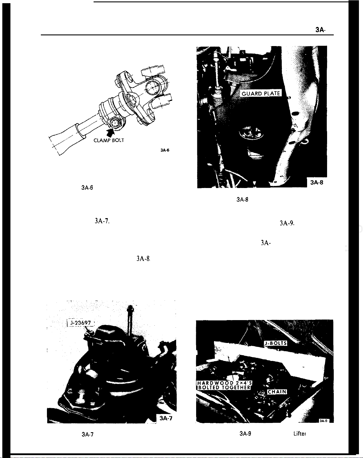
Before raising vehicle, install Hooks J-23697 on re-
spective vehicle side to cross member and upper con-
trol arm. See Figure 3A-7.
1. Raise car and support at rear of front frame rails.
2. Remove front wheel.
3. At the lower control arm ball joint, remove castle
nut cotter pin and slacken back nut so that the thread
can no longer be damaged.
4. With a suitable drift, detach ball joint from steer-
ing knuckle. With jack, lift up lower control arm,
unscrew castle nut and remove Hooks J-23697.
5. Unscrew upper control arm ball joint and suspend
front wheel hub and brake caliper in wheel house. Do
not turn upper control arm ball joint flange, as this
would result in a change of camber.
6. Remove defective lower control arm ball joint
using Tools J-9519 and Receiver J-23754.
Installation GT
CAUTION:
Fasteners are important attachingparts in
that they could affect the performance of
vitaI
com-
ponents and systems, and/or could result in ma&r
repair expense. They must be replaced with one of
the same part numer or with an equivalent part if
replacement becomes necessary. Do not use a
re-
placement part of lesser quality or substitute design.
Torque values must be used as specified during reas-
sembly to assure proper retention of these parts.
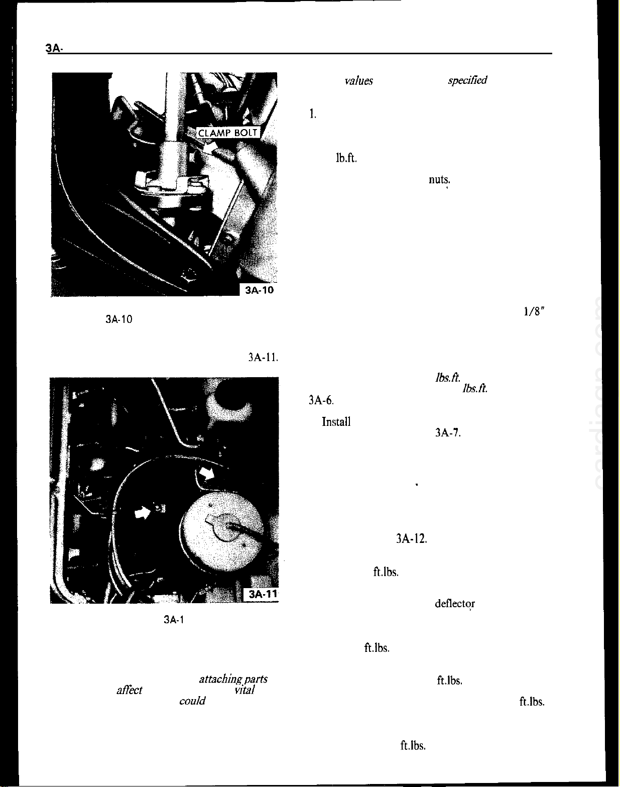
1. When pressing the ball joint in place, make certain
the locating notch in the lower rim of the ball joint
matches the alignment reference mark placed on the
lower control arm prior to removal. The notch in the
ball joint bottom plate, identifying the direction of
the elongated slot, must point towards the brake
drum backing plate. See Figure
3A-17.
Alignment
must be within 2 degrees of lower control arm center-
line. If proper positioning of the ball joint is not
accomplished, the result is a limitation of the neces-
sary ball stud movement. If ball stud movement is
limited, an interference between the ball stud and
housing is created, and binding or even fracture may
occur. Replacement ball joints may or may not have
marking notch as shown in Figure
3A-20.
If it does
not have a marking notch, the joint is completely
symetrical and may be installed in any position.
When pressing in ball joint do not press on bottom
plate, but on ball joint housing only.
2. Install dust cap on lower ball joint and fill with
chassis lubricant. Attach dust cap retainer.
3. Press ball joint into steering knuckle. Use
J-
9519-3 as installer and J-21690 as a supporting
sleeve.
4. Install castle nut on ball joint stud and torque to
40
Ib.ft.
Install new cotter pin.
5. Reconnect shock absorber to lower control arm
and torque to 30 lb.ft.
6. Remove spring compressor.
7. Install front wheel, and lower the car.
8. Always check caster and camber after ball joint
replacement.
Installation Opel 1900
-
Manta
CAUTION:
Fasteners are important attachingparts in
that they could
aff’ect
the performance of vital com-
ponents and systems, and/or could result in ma&r
repair expense. They must be rep/aced with one of
the same part number or with equivalent parts, if
rep/acement
becomes
necessary.
Do not use a
re-
p/acement part of lesser quality or substitute design.
Torque valves must be used as specitied during
reas-
sembIy to assure proper retention of these parts.
1. Drive new ball joint into lower control arm using
Tools J-9519 as installer and J-23755 as a supporting
sleeve. Do not strike onto ball joint bottom.
The ball joint is maintenance-free. It is supplied as an
assembly only and cannot be disassembled further.
2. On new lower control arm ball joint, make sure
that the marking groove in the housing bottom in
alignment with the axis of the lower control arm.
Permissible deviation: minus 2 degrees to plus 2 de-
grees.
This is required, to obtain the maximum freedom of
movement of the ball stud in the housing. See Figure
3A-18.
3. Attach steering knuckle together with front wheel
hub and brake caliper to lower control arm ball joint.
Torque castle nut to 54
ft.lbs.
4. Attach ball joint to upper control arm and torque
to 29
ft.lbs.
Always use new self-locking nuts.
5. Install wheel and tighten nuts to a torque of 65
ft.lbs.
6. Lower car and check caster and camber.
cardiagn.com

3A- 10 1973 OPEL SERVICE MANUAL
Figure 3A-18 Lower Ball Joint Notch Opel 1900
-
Manta
UPPER CONTROL ARM REMOVAL AND
INSTALLATION
Removal GT
1. Raise car and support at rear of front frame rails.
2. Remove front wheel.
3. Install spring compressor and compress spring
until there is 3-l/8” between compressor and lower
spring leaf.
4. Remove cotter pin and castle nut from upper ball
joint stud. Discard cotter pin.
5. Use tie rod remover J-21687 remove ball joint
from.steering knuckle. 6. Support brake drum to
relieve tension on brake hose.
7. Remove hex nut from upper control arm shaft.
Remove shaft and washers from shock absorber sup
port. Do not damage threads on control arm shaft.
8. Remove control arm from car. Do not lose inner
toothed washers. Note size and location of toothed
washers.
Removal
Opel
1900 . Manta
1,
Raise car and support at rear of front frame rails.
2. Remove front wheel
3. Unscrew upper control arm to cross member
self-
locking attaching nut.
4. Unscrew ball joint from upper control arm. Do not
turn upper control arm ball joint flange, as this
would result in a change of camber.
5. Support front wheel hub so that brake hose is not
stressed.
6. Pull out upper control shaft to cross member at-
taching bolt and remove control arm. Shims have to
be reinstalled in their original location to maintain
the proper caster setting.
Installation GT
CAUTION:
Fasteners are important attaching parts in
that they could affect the the perfonmmce of vital
components and systems, and/or could result in ma-
jor repair expense. They must be replaced with one
of the same part number or with an equivalent part
if replacement becomes necessary. Do not use a re-
placement part or lesser quality or substitute design.
Torque values must be used as specified during reas-
sembly to assure proper retention of these parts.
If rubber bushings on control arms are worn, arms
must be replaced.
1. Slide rubber rings over bushings. Slide rings over
inner sleeves of bushings. Place control arm in posi-
tion on shock absorber support, installing toothed
washers in their original positions. See Figure 3A-
19.
2. From front to rear, install control arm shaft. If
necessary, align washers and control arm bushings
with a small drift prior to installing control arm
shaft. See Figure
3A-19.
3. Tighten hex nut on control arm shaft finger tight.
4. Increase tension on spring compressor in order to
relieve tension on control arm shaft. Then torque hex
nut on control arm shaft to 33
Ib.ft.
5. Press ball joint stud into steering knuckle and
torque castle nut to 29 lb.ft. Install new cotter pin.
6. Remove spring compressor and lower car.
7. Check front end alignment.
Installation Opel
1900.
Manta
CAUTION:
Fasteners are important attaching parts in
that they could
at?&
the performance of vital com-
ponents and systems, and/or coo/d result in major
repair expense. They must be replaced with one of
the same part number or with equivalent parts, if
replacement becomes necessary. Do not use a re-
cardiagn.com

FRONT SUSPENSION
3A- 11
UPPER CONTROL ARM SHAFT
INNER SLEEVE
OUTER SLEEVE
RUBBER DAMPENIN
GUIDE SLEEVE
ABSORBER SUPPOR
SHOCK ABSORBER SUPPORT
ON FRONT SUSPENSION
CROSS MEMBER
-
TOOTHED WASHER
l-
UPPER CONTROL ARM RUBBER BUSHINGS
PLATE WASHER
Figure
3A-19
Upper Control Arm Shaft and Bushings
placement part of lesser quality or substitute design.
Torque
valves
must be used as specified during
reas-
semb/y to assure proper retention of these parts.
1. On installation of the upper control arm, make
sure that damper bushing with the rubber shoulder
on both sides is always located in the rear.
2. Attach upper control arm to cross member and
torque to
40
lb.ft.
Always use new self-locking hex
nut. The upper control arm must be tightened in
horizontal position only. This applies also to all other
attaching joints in connection with rubber damper
bushings in the control arms of the front suspension
so that the rubber parts under load are in an almost
twist-free condition. This position exists, if the hooks
J-23697 are used.
3. Attach ball joint to upper control arm and torque
to 29
lb.ft.
4. Install wheel and torque nuts to 65
lb.ft.
Lower
car.
LOWER CONTROL ARM REMOVAL AND
INSTALLATION
Removal GT
1.
Raise car and support at rear of front frame rails.
2. Remove front wheel.
3. Remove cotter pin from castle nut on ball joint
stud and back off castle nut two (2) turns. Hit ball
stud a sharp blow to break it loose. DO NOT
REMOVE NUT.
4. Install spring compressor (J-21689) and compress
spring until a distance of
3-l/8
inches is achieved
between spring compressor and lower spring leaf.
5. Disconnect and compress shock absorber.
6. Support rail of spring compressor with a jack.
Remove lower control arm from frame cross mem-
ber. Nuts may have to be removed with a punch. See
Figure 3A-20. Discard the lock nuts.
7. Remove lower ball joint stud nut. Slightly lower
cardiagn.com

3A- 12 1973 OPEL SERVICE MANUAL
Figure 3A-20 Lower Control
Arln
Attachment
jack so that spring and lower control arm assembly
is removed from the front cross member and steering
knuckle.
8. Lower jack, spring compressor, and front spring
with control arm assembly. Remove lower control
arm to spring nuts.
9. Release spring compressor and remove control
arm attaching bolts and control aRn.
Removal Opel
1900.
Manta
1. Prior to raising car, install upper control arm
hooks J-23697.
2. Raise car and support with stands. Hoist should
be left in the raised position to maintain pressure on
lower control arm.
3. Remove front wheel.
4. Detach both stabilizer supports from cross mem-
ber to body support.
5. In lower control arm, remove self-locking hex
head bolt from stabilizer support and remove
washer.
6. Using a pry bar, pry stabilizer bar out of lower
control arm support.
7. Remove shock absorber.
8. At lower control arm ball joint, remove castle nut
cotter pin and remove nut.
9. With suitable drift, detach lower control arm ball
joint from steering knuckle.
10. Loosen nut that retains lower control to front
cross member.
11. Slowly lower hoist to release spring tension.
12. Swing lower control arm downwards and remove
front spring.
13. Remove nut that retains lower control arm to
front cross member and remove lower control arm.
Installation GT
CAUTION:
Fasteners are important attaching parts in
that they could affect the performance of
vital
com-
ponents and systems, and/or could result in major
repair expeme. They must be replaced with one of
the same part number or with an equivalent part if
replacement becomes necessary. Do not use a re-
placement part of lesser quality or substitute design.
Torque values must be used as specified during
reas-
sembly to assure proper retention of these parts
1. Attach lower control arm to front spring eye.
Torque bolts to 18
1b.R.
2. Install spring compressor and with a jack raise
spring compressor with spring and control arm as-
sembly into position for pressing ball joint into steer-
ing knuckle.
3. Press ball joint into steering knuckle. Use
J-
;lYN;: as installer and J-21690 as a supporting
4. Install castle nut on ball joint stud and torque to
54
lb.ft.
Install new cotter pin.
5. Attach lower control arm to frame cross member
using new lock nuts.
cardiagn.com

FRONT SUSPENSION
3A-
13
6. Reconnect shock absorber to lower control arm
and torque to 30
Ib.ft.
7. Remove spring compressor.
8. Install front wheel, and lower the car.
9. Check front end alignment.
Installation Opel 1900 Manta
CAUTION:
Fasteners are important attachingparts in
that they could
aff&
the-performance of
vitaI
com-
ponents and systems, and/or could resu/t in major
repair expenses. They must be repraced with one of
the same part number or with an equivaknt part, if
replacement becomes necessary. Do not use a re-
placement part of
ksser
quality or substitute design.
Torque values must be used as specified dmitig reas-
sembIy to assure proper retention of these parts.
1. Loosely attach lower control arm to front cross
member.
2. Properly seat spring between lower control arm
and cross member.
3. Raise jack and place lower control into position.
4. Attach lower control ball joint to steering knuckle
and torque nut to 54
Ib.ft.
5. Tighten lower control arm to cross member bolt
to 43
lb.ft.
6. Attach stabilizer bar to lower control arm and
torque to 87
lb.ft.
7. Attach stabilizer bar to cross member to body
support.
8. Install shock absorber and torque lower attaching
nut and bolt to 30
lb.ft.
9. Install nuts on upper shock absorber attaching
studs. Tighten nuts until a distance from top of nut
to stud is approximately
l/2
inch.
10. Install front wheels and tighten nuts to 65
lb.ft.
11. Remove stands and lower car.
STEERING KNUCKLE REMOVAL AND
INSTALLATION
Removal GT
1. Raise car and support with stands.
2. Remove wheel nuts. Remove wheel assembly.
Figure 3A-2 1 Caliper Attachment
4. Remove spindle grease cap. Remove cotter pin
and spindle nut. Remove wheel hub with disc.
5. Install J-21689 spring compressor and compress
spring until 3-l/8” clearance is obtained between
spring compressor and lower spring leaf.
6. Remove upper ball joint using tie rod remover,
J-
21687.
7. Remove shock absorber at lower attachment only.
8. Remove lower ball joint using J-21687 remover
and remove steering knuckle. Remove dust shield
from steering knuckle.
Removal Opel
1900.
Manta
1. Raise car and support with stands.
2. Detach brake caliper and steering arm from steer-
ing knuckle.
3. Remove castle nut cotter pin, unscrew nut and
pull steering knuckle off upper control arm ball joint.
4. Unscrew brake caliper and suspend it in wheel
house.
5. Remove front wheel hub.
6. Unscrew steering arm and brake cover plate from
cardiagn.com

3A. 14 1973 OPEL
SERVkE
MANUAL
Figure 3A-22 Caliper Removed and Hung by Wire
steering knuckle. Swing steering arm and tie rod to
the side.
7. Remove castle nut cotter pin, unscrew nut and
pull steering knuckle off lower control arm ball joint.
Installation GT
CAUTION: Fasteners are important attachingparts in
that they could affect the performance of
viral
com-
ponents and systems, and/or could result in major
repair expense. They must be replaced with one of
the same part number or with an equivalent part if
replacement becomes necessary. Do not use a re-
placement part of lesser quality or substitute
desig.
Torque values must be used as specified during reas-
sembly to assure proper retention of these parts.
1. Always replace paper gasket when installing dust
shield on steering knuckle. Lightly coat both surfaces
of paper gasket with chassis lubricant before installa-
tion and torque attaching bolts to 47
lb.ft.
2. Install lower ball joint in steering knuckle. Torque
castle nut to 54
Ib.ft.
Install new cotter pin.
3. Attach shock absorber at lower end. Torque bolts
to 30 lbs. ft.
4. Install upper ball joint. Torque castle nut to 29
lb.ft.
Install new cotter pin.
5. Remove spring compressor.
6. Install hub and disc on spindle and tighten spindle
nut as stated under MAINTENANCE AND AD-
JUSTMENTS in this section.
7. Install caliper on steering knuckle and torque bolts
to 72
lb.ft.
See Figure
3A-21.
8. Install wheel and torque wheel nuts to 65
lb.ft.
Installation Opel 1900
-
Manta
CAUTION: Fasteners are important attachingparts in
that they could
affit
the performance of vital com-
ponents and systems, and/or could result in
ma&
repair expense. They must be replaced with one of
the same part number or with equivalent parts, if
repfacement becomes necessary. Do not use a re-
placement part of lesser quality or substitute design.
Torque values must be used as specified during reas-
sembly to assure proper retention of these parts.
1. Attach steering knuckle to lower control arm ball
joint. Torque castle nut to 54
lb.ft.
2. Atl,ach brake cover plate and steering arm to steer-
ing knuckle. If required, install new paper gasket
between cover plate and steering knuckle. Care for
proper seat of T-head bolts. See Figure
3A-23.
Figure 3A-23 Attaching Brake Cover Plate
3. Install front wheel hub and brake caliper.
4. Attach steering knuckle to upper control arm ball
joint. Torque castle nut to 40
lb.ft.
5. Steering arm to steering knuckle
_
58
lb.ft.
6. Brake caliper to steering knuckle
-
72
lb.ft.
7. Adjust front wheel bearing clearance.
8. Remove stands and lower car
cardiagn.com

FRONT SUSPENSION 3A- 15
SHOCK ABSORBER REMOVAL AND
INSTALLATION
Removal Opel
1900.
Manta
1. Raise car and support with stands.
2. Remove upper attaching nuts from shock ab-
sorber.
3. Remove lower attaching nut, lockwasher, and
bolt.
4. Compress shock absorber and remove from car.
Removal GT
1. Remove air cleaner. See Figure 3A-24.
Figure 3A-24 Removal of Air Cleaner
2. Remove plastic cover over shock absorber upper
attachment.
3. Raise car and support with stands.
4. Remove upper attaching nuts from shock ab-
sorber.
5. Remove lower attaching nut, lockwasher, and
bolt.
6. Compress shock absorber and remove from car.
Installation Opel
1900.
Manta
1. Inspect shock absorber for damage and seal leaks.
Always replace the upper and lower rubber grom-
mets when replacing a shock absorber.
2. Install the lower grommet retainer and grommets
on shock absorber. Compress shock absorber and
place in position.
3. Install lower attaching bolt and nut. Torque to 30
lb.ft.
4. Install nuts on upper attaching studs. Tighten nuts
until distance from top of nut to stud is approxi-
mately
l/2
inch. See Figure
3A-25.
5. Install plastic cover.
Installation GT
1. Inspect shock absorber for damage and seal leaks.
Always replace the upper and lower rubber grom-
mets when replacing a shock absorber.
2. Install the lower grommet retainer and grommets
on shock absorber. Compress shock absorber and
place in position.
3. Install lower attaching bolt and nut. Torque to 30
lb.
ft.
4. Install nuts on upper attaching studs. Tighten nuts
until distance from top of nut to stud is approxi-
mately
l/2
inch. See Figure
3A-25.
5. Install plastic cover.
6. Install air cleaner.
FRONT SPRING REMOVAL AND INSTALLATION
Removal (GT)
1. Raise car and support at rear of front frame rails
with stands.
2. Remove front wheels.
3. Remove cotter pin from castle nut on lower ball
joint studs and back off castle nut two (2) turns. Hit
ball stud a sharp blow to break it loose. Do not
remove nut.
4. Install J-21689 spring compressor and compress
the spring until 3-l/8” clearance is obtained between
spring and compressor.
5. Disconnect both shock absorbers at their lower
attachment. Compress both shock absorbers.
6. Support the rail of J-21689 Spring Compressor
with a jack. Remove lower control arm to cross
member attaching nuts and bolts.
cardiagn.com

3A- 16 1973 OPEL SERVICE MANUAL
INNER RUBBER
STUD.
1
/2”
\
E
/
PLASTIC COVER
DAMPENING RING
RETAINER
RUBBER DAMPENING RING- -z
SELF-LOCKING NUT
UPPER RUBBER
GROMMET RETAINER
LOWER
RUBI
GROMMET RETAINER WHEEL HOUSE
SHOCK ABSORBER
SHOCK ABSORBER
SA-25
Figure
3A-25
Shock Absorber Upper Attachment
7. Remove lower ball joint stud nuts. Slightly lower
jack so that the spring and lower control arm assem-
bly is removed from the front cross member and
steering knuckle.
8. Lower jack, spring compressor, and front spring
and control arm assembly. Remove lower control
arm to spring nuts.
9. Relieve tension on spring compressor and remove
control arm attaching bolts and control arms.
Removal (Opel 1900
-
Manta)
1. Prior to raising car, install upper control arm
hooks J-23697.
2. Raise car and stipport with stands. Hoist should
be left in the raised position to maintain pressure on
lower control arm.
3. Remove front wheel.
4. Detach both stabilizer supports from cross mem-
ber to body support.
5. Remove shock absorber.
6. At lower control arm ball joint, remove castle nut
cotter pin and remove nut.
7. With suitable drift, detach lower control arm ball
joint from steering knuckle.
8. Loosen nut that retains lower control to front
cross member.
9. Slowly lower hoist to release spring tension.
10. Swing lower control arm downwards and remove
front spring.
Installation (GT)
CAUTION:
Fasteners are important attachingparts in
that they could
at&t
the performance of vital com-
ponents and systems, and/or could result in major
repair
expense. They must be replaced with one of
the same part number or with an equivalent part if
replacement becomes necessary. Do not use a
re-
placement part oflesser quality or substitute design.
cardiagn.com

FRONT SUSPENSION 3A- 17
Torque values must be used as specified during reas-
sembly to assure proper retention of these parts.
1. Attach lower control arm to front spring eye.
Torque bolts to 18
lb.ft.
2. Install spring compressor on spring and compress
spring to appropriate length.
3. Raise jack with spring compressor, spring and
control arm assembly into position under the car.
4. Install lower ball joints and torque nuts to 54
Ib.ft.
Install new cotter pin.
5. Attach lower control arms to frame cross member
using new lock nuts.
6. Attach both shock absorbers. Torque bolts to 30
lb.ft.
7. Remove spring compressor.
8. Install front wheels.
On replacement of the damper bushings on the front
springs, only the one-part damper bushing is in-
stalled for either the two-leaf or three-leaf spring.
For proper location of the marking lugs, see Figure
3A-26.
Installation (Opel 1900. Manta)
CAUTION:
Fasteners are important attachingparts in
that they co&d affect the performance of vital com-
ponents and systems, and/or could result in major
repair expense. They must be replaced with one of
the same part number or with an equivalent part, if
replacement becomes necessary. Do not use a re-
placement part of lesser quality or substitute design.
Torque values must be used as specified during reas-
sembly to assure proper retention of these parts.
1. Properly seat spring between lower control arm
and cross member.
2. Raise jack and place lower control into position.
CROSS SECTION
SA-26
Fig. 3A-26 Front Spring Damper Bushing.
3. Attach lower control ball joint to steering knuckle
and torque nut to 54
lb.ft.
4. Tighten lower control arm to cross member bolt
to 43 lb.ft.
5. Attach stabilizer bar to cross member to body
support.
6. Install shock absorber and torque lower attaching
nut and bolt to 30
lb.ft.
7. Install nuts on upper shock absorber attaching
studs. Tighten nuts until a distance from top of nut
to stud is approximately
l/2
inch.
8. Install front wheels and tighten nuts to 65
lb.ft.
9. Remove stands and lower car.
SPECIFICATIONS
BOLT TORQUE AND FRONT END ALIGNMENT
cardiagn.com

3A- 16 1973 OPEL SERVICE MANUAL
SPECIFICATIONS
Torque Specifications
Use a reliable torque wrench to tighten all parts listed to insure proper
tightness without straining or distorting parts. These specifications are for
clean and lightly-lubricated threads only; dry or dirty threads produce in-
creased friction which prevents accurate maasurement of tightness.
Location
Front Suspension Crossmember to Front Frame
Clamp, Steering Mast to Steering Mast Flange
(GT)
...............................
.
........................................................
Clamp, Steering Mast to Steering Mast Flange
(1900
-
Manta)
..................................................................
Clamp,
Upper
Universal
Joint
(GT)
..................................
Clamp, Lower Universal Joint (GT)
..................................
Wheel Nuts
............................................................................
Lower Control Arm Shaft to Lower Control Arm
..........
Lower Control Arm Ball Joint to Steering Knuckle
......
Upper Control Arm Ball Joint to Steering Knuckle
(GT)
........................................................................................
Upper Control Arm Ball Joint to Steering Knuckle
(1 900 Manta)
..................................................................
Upper Control Arm Ball Joint to Upper Control Arm
Shock
Absorber
to
Lower
Control Arm
..........................
Steering Arm to Steering Knuckle (1900
-
Manta)
......
Brake Backing Plate or Brake Disc Shield and
Steering Arm to Steering Knuckle
(GTJ
Hex Head Bolt M 10
......
Hex Head Bolt M
8......
Brake Backing Plate to Steering Knuckle
(1900 Manta)
..................................................................
Brake Caliper to Steering Knuckle
........... ......................
Lower Control Arm to Front Spring Eye (GT)
................
Brake Disc to Front Wheel Hub
........................................
Upper Control Arm to Crossmember (1900
-
Mantaj
Lower Control Arm to Crossmember (1900
-
Manta)
Steering Gear Housing to Front Suspension
Crossmember (GT)
............................................................
Steering Gear Housing to Front Suspension
Crossmember (1900
-
Manta)
........................................
Stabilizer Bar to Lower Control Arm
(Opel 1900
-
Manta)
........................................................
Tie Rod Clamp Bolts
(GTJ ....................................................
Castle Nut, Tie Rod
to
Steering Arm
..............................
Upper Control Arm Shaft to Shock Absorber Support
and Upper Control Arm (GT)
..........................................
Cross Member to Body Support Attachment
................
Front Suspension Assembly to Frame
............................
Front End Alignment Specifications
Torque
Lb.Ft.
36
15
22
14
22
65
40
54
29
ii
30
58
47
18
58
72
18
36
40
43
18
30
87
:i
33
58
47
Model Caster’
Camber”
1900 ‘3
l/2-6
l/2
GT
3+1
-:%
+
*Permissible deviation from left to right wheel
-
Max. 1’.
Toe-In”
Min.-Max.
l/8-3/
16
l/32-1/8
Outer Wheel
When Inner
Wheel at 20
19
l/4
18
l/2
cardiagn.com

STEERING LINKAGE
38.19
STEERING LINKAGE
CONTENTS
Subject
DESCRIPTION AND OPERATION:
Description
and
Operation of Tie
Rods
. . . . . . . . . . . . . . . . . . . . . .
DIAGNOSIS: (Not Applicable)
MAINTENANCE AND ADJUSTMENTS: (Not
Applicable)
MAJOR REPAIR:
Removal and
Installation of
Tie Rods
. . . . . . . . . . . . . . . . . . . . . . . .
Disassembly
and Reassembly of
Tie
Rods
. . . . . . . . . . . . . . . .
SPECIFICATIONS:
Tightening Specifications ..,.............................................
Page No.
38-19
3B-19
38-21
jB-21
DESCRIPTION AND OPERATION
2. Using remover J-21687, pull outer tie rod ball
studs out of steering arms. See Figure
3B-2.
DESCRIPTION AND OPERATION OF TIE RODS
Tie rods on the GT are connected to both rack ends
by means of a ball joint. Two rubber bellows between
ball joint and steering gear housing protect rack and
ball joints against dirt, dust and mud. The ball joints
of the tie rods do not require service.
Tie rods on the Opel l&O and Manta are connected
to both rack ends by means of a axial joint. Two
rubber bellows between the axial joint and steering
gear housing protect the rack and axial joints against
dirt, dust, and mud. The ball joint of the tie rod ends
on
the Opel
1900
and Manta are maintenance free
and must not be disassembled.
MAJOR REPAIR
REMOVAL AND INSTALLATION OF TIE RODS
38-2
Removal
Figure
38-2
Removing Ball Stud
In order to avoid the possibility of dirt entering the
steering gear assembly via the rack, it is recom-
mended that rods and area immediately surrounding
the gear assembly be wiped free of loose dirt prior to
removal.
3. Remove clamp securing one end of rubber bellows
to tie rods and slip bellows off tie rods to expose nut
or lock plates. See Figure
3B-3.
1. Remove cotter pins securing nuts on tie rod ends
and remove nuts. Discard cotter pins.
4. On the GT, bend up round edges of lock plate
from tie rod ball studs and unscrew ball studs From
rack. See Figure
3B-4.
cardiagn.com

Figure 38-3 Bellows Removed From Tie Rod GT
5. On the Opel
1900
-
Manta, unscrew tie rod from
axial joint. It is important that rack be held secure
with open end wrench to prevent damage to rack
teeth.
38.
20 1973 OPEL SERWCE MANUAL
Figure 38.4 Removing Tie Rods. GT
Installation . GT
CAUTION:
Fasteners are important attaching parts in
that they could affect the performance of
vital
com-
ponents and systems, and/or coo/d result in major
repair expense. They must be replaced with one of
the same part number or with an equivalent part if
replacement becomes necessary. Do not use a re-
placement part or lesser
quaJity
or sub.Mute design.
Torque
vaJues
must be used as specified
during
reas-
sembJy
to assure proper retention of these parts.
1. Install new lock plates onto tie rod ball studs and
screw ball studs into rack while holding bent tab of
lock plates against flat on rack. Torque ball studs 43
lb.ft. See Figure
3B-5.
It is important that rack be
held secure with open end wrench to prevent damage
to rack teeth.
Figure 38-5 Bending Lock Plate Over Ball Stud
-
GT
2. Bend round edges of lock plate over
flat
on ball
stud
‘to
lock ball stud in position.
3. Position rubber bellows and hose clamps over tie
rods and adjust clamp so that wire ends are pointing
in same direction as adjusting screw. Check that bel-
lows are not twisted and will compress and expand
properly.
4. Connect outer tie rod ball stud to steering arm,
torque castle nut to 29
lb.ft.,
and lock in position
with new cotter pin.
Installation Opel
1900.
Manta
CAUTION:
Fasteners are important attachingparts in
that they could
ah%
the
performance
of vital com-
ponents and systems, and/or
couJd
reslllt
in major
repair expense. They must be replaced with one of
the same part number or with an
equivalenr
part if
repJacement
becomes necessary. Do not use a re-
placement part of lesser quality or substitute design.
Torque valves must be used as specified during reas-
sembfy to assure proper retention of these parts.
1. Screw tie rod into axial joint.
2. Attach tie rod end to steering arm and torque nut
to 29 lb.ft. Install new cotter pin.
3. Adjust toe-in and then torque lock nut of both tie
rods to 47 lbft.
cardiagn.com
Table of contents
Other Opel Automobile manuals

Opel
Opel CASCADA 2014 User manual

Opel
Opel 2010 Astra User manual

Opel
Opel ASTRA 2014 User manual

Opel
Opel 2010 Astra User manual

Opel
Opel 2010 Astra User manual

Opel
Opel 2013 Corsa User manual

Opel
Opel Automobile Owner's User manual

Opel
Opel 2013 Meriva User manual

Opel
Opel Automobile User manual

Opel
Opel VIVARO User manual

Opel
Opel 2015 Combo User manual

Opel
Opel CORSA User manual

Opel
Opel VIVARO User manual

Opel
Opel 2009 Zafira User manual

Opel
Opel Meriva User manual

Opel
Opel 2016 ASTRA K User manual

Opel
Opel 1991 Astra Instruction manual

Opel
Opel 2010 Astra User manual

Opel
Opel Automobile User manual

Opel
Opel Rocks-E 2021 User manual