Step 1
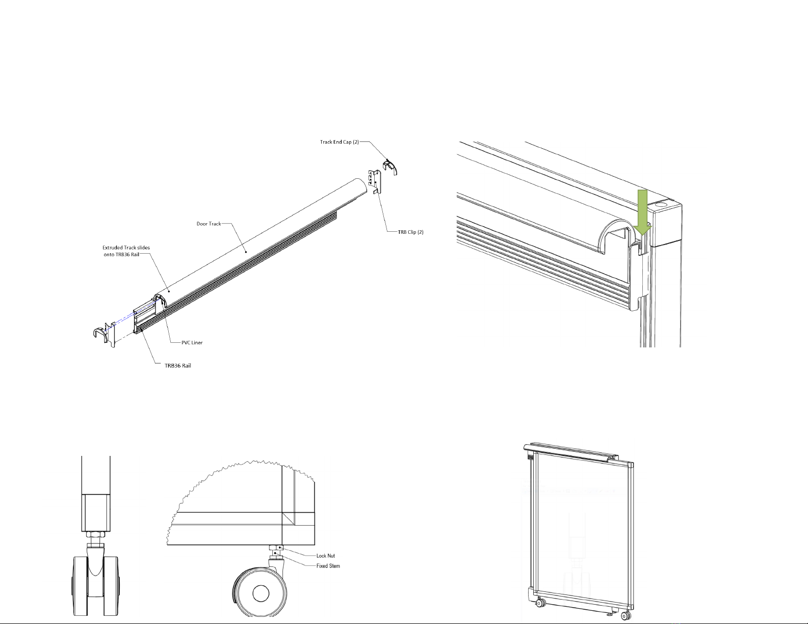
Assemble the Door Track. Slide the Track onto the TRB Rail.
Attach the Track End Caps. Set the TRB clips into the TRB
rail to mount the track to the A02 Panel.
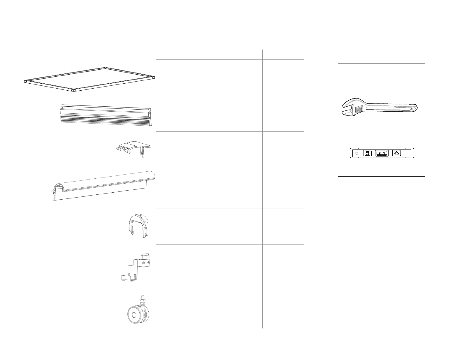
ASSEMBLY GUIDE
Step 2
Set the TRB Clips and Track onto the highest slot position
on the A02 Panel. Make sure the teeth engage in the rails by
applying a downward force.
Step 3
Layout the door and unbox the casters. Thread the caster
stem into the bottom of the door, aligning the caster to roll
parallel to the plane of the Panel (VERY IMPORTANT AS THIS
KEEPS THE DOOR IN LINE WITH THE TRACK). Tighten the
lock nut against the door frame to lock the caster position.
Step 4
Stand the door up, positioned inside the track. Adjust the
panel height to relieve any rubbing of the door to the track
liner. Additional adjustment can be found in Step 6.
Step 2: Set the TRB Clips and Track onto the highest
slot position on the A02 Panel. Make sure the teeth
engage in the rails by applying a downward force.
3
Step 1: Assemble the Door Track. Slide the Track onto the TRB Rail. Attach the
Track End Caps. Set the TRB clips into the TRB rail to mount the track to the A02
Panel.
Step 3: Layout the door and unbox the casters. Thread the caster stem into the
bottom of the door, aligning the caster to roll parallel to the plane of the Panel
(VERY IMPORTANT AS THIS KEEPS THE DOOR IN LINE WITH THE TRACK). Tighten the
lock nut against the door frame to lock the caster position.
Step 4: Stand the door up, positioned inside the
track. Adjust the panel height to relieve any rubbing
of the door to the track liner. Additional adjustment
can be found in Step 6.