Open Range Recreational Vehicle User manual

Maintenance
Manual
Guidebook to
Routine Maintenance of Your
Recreational Vehicle

Maintenance Manual
This booklet has been designed and written to supply
information regarding maintenance requirements for all
makes and models built by Open Range RV Company.
As the owner of a new Open Range product, it is
important to recognize the importance of performing routine
maintenance during the warranty period. Just like oil changes
in your tow vehicle – if proper maintenance is not performed
the warranty coverage can be denied; this also applies to your
recreational vehicle.
On the reverse side of the customer delivery sheet is
the warranty coverage information. Note the twelve (12)
exclusions, items.
Familiarizing yourself with this manual and using the
maintenance chart in the back of the manual will help you
make sure that proper maintenance is performed. But
remember, maintenance is routine service and is not covered
by warranty.
With proper and scheduled maintenance on your Open
Range RV, we believe you will enjoy your RV for many years
to come.
Enjoy the journey,
Open Range RV

TABLE OF CONTENTS
Chapter I – Undercarriage
Frame.............................................1
Coupler ...........................................1
Stabilizer Jacks .....................................1
Jacks .............................................2
Tires..............................................2
Wheels............................................3
Axles .............................................4
Brakes ............................................6
Springs/Shackles....................................8
Steps .............................................9
Chapter II – Exterior
Metal ............................................11
Fiberglass ........................................11
ABS Plastics ......................................11
Exterior Roof ......................................12
Extrusions and Vents................................13
Vinyl Tire Covers ...................................13
Chapter III – Systems
Propane System ...................................14
Plumbing System...................................15
Electrical System ...................................16
Chapter IV – Appliances
Furnace ..........................................18
Water Heater ......................................19
Stove, Range, Cooktop ..............................20
Refrigerator .......................................21
Air Conditioner.....................................23

Chapter V – Interior
Paneling..........................................25
Linoleum / Vinyl Floor ...............................25
Carpet ...........................................25
Hardwood Floor ....................................25
Counter Tops ......................................25
Solid Surface Counter Tops ..........................25
Window Mini Blinds .................................27
Day Fabric Shades .................................27
ABS Plastic Components ............................27
Soft Touch Ceiling ..................................27
Drapes ...........................................27
Cushion Covers ....................................27
Furniture .........................................28
Windows .........................................28
Smoke Alarm ......................................28
Propane and CO Detector ............................28

1
Chapter I – Undercarriage
Your Open Range recreational vehicle is designed to be as
maintenance free as possible. However, all moveable vehicles require
some care to reduce the possibility of unwanted breakdowns during
travel. Maintenance of your RV may not seem necessary at the time of
purchase, yet it is very important to keep your coach in it’s best condition
for your enjoyment. Normal maintenance is required to maintain warranty
coverage, reduce wear, and prolong the life of your coach.
1. FRAME
The steel frame on your Open Range recreational vehicle is cleaned
with a high pressure phosphate spray wash that removes oils, dirt, and
residue. After cleaning the frame is placed in an oven at 200°F, high
quality, water borne paint is then applied. A nal curing process is then
applied to produce a quality paint application.
No matter what quality or type of paint process is used, we must
remember that during travel the frame is exposed to stones, sand, road
debris, and any other objects found on the road. These items will cause
scratching and chipping of the paint inviting rust to begin from moisture.
Your frame needs to be inspected and examined every year to touch up
or repaint as normal maintenance. We suggest this be performed each
fall before storage to guard against winter moisture.
The paint to use is a gloss black, ozone safe exterior paint with no
uorocarbon, in a spray can.
You may wish to purchase a commercial rust proof undercoating
treatment, such as, Ziebart®, etc. However, even such higher priced
treatments are subject to road debris and damage.
2. COUPLER (Travel Trailers)
For the ball on your hitch use a light amount of chassis grease.
Lubricate the coupler’s pivot points with silicone spray. Avoid grease
or oil as they will draw dirt, potentially
damaging the coupler.
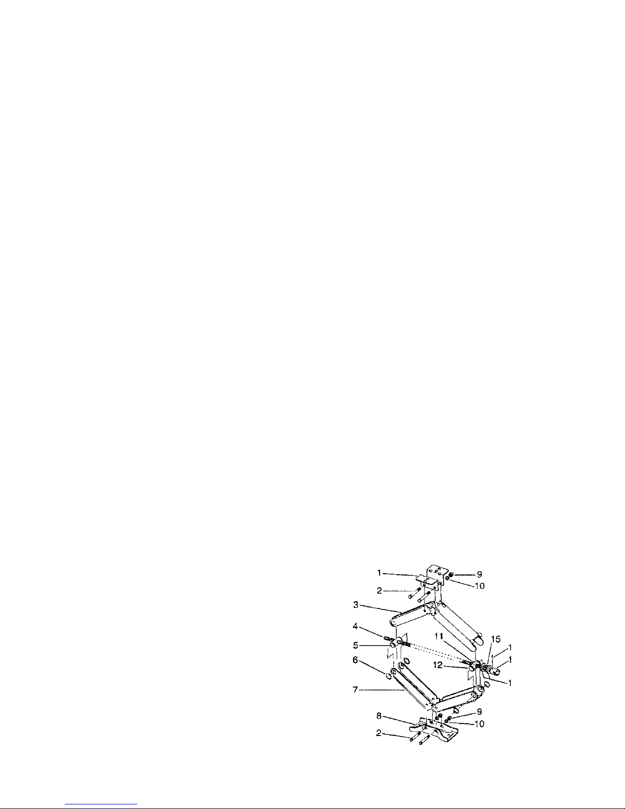
3. STABILIZER JACKS
On item #4 (illustration), drive screw,
spray silicone is recommended to be
applied two or more times per year. DO
NOT use oil or grease as it will attract dirt
and grit causing gradual deterioration.
Should jacks become rusty you may
wish to paint them; to stay more attractive

2
and easier to function. Avoid painting the main operating screw.
4. JACKS
A. Travel Trailers
On the top of the jack is a metal cover attached with a wire spring
clip. Remove cover and inspect gears for grease. Re-grease if there is
none there or it has dried out. Some brands of jacks have a hole placed
just below these gears to insert oil for lubrication of the ram so it will move
smoothly, ten to twenty drops annually will do the job.
B. Landing Gear Jacks (Fifth Wheels)
a. Extend landing legs as far as possible, clean drop tube and inner
ram tube. Coat exposed surface or tubes with silicone spray
lubricant.
b. Coat inside of handle alignment tube with silicone spray lubricant.
c. Oil shaft bushing in gear box and leg gear heads with SAE 30 oil.
d. Lubricate gears in gear box and landing gear heads with extreme
pressure grease.
On 2000 lb. rated jacks there is a at plate on top attached with spring
clips. (Not in production since 2003) On 3000 lb. & 4000 lb. jacks there
is a metal cover on top of jack. Remove these covers to perform item “d.”
2000 lb. jacks are obsolete and not available after January 1, 2004.
C. 12 Volt DC Motor
For Electric Drive Motor Landing Legs, check wiring connections at
battery, twice each year. Clean terminals with a solution of baking soda
and water. Cover with thin coat of grease.
NOTE: Electric Drive Motor is lubricated at factory and requires no
further lubrication.
The Electric Drive Motor Landing Leg system is protected by a 30
amp fuse. If replacement is necessary, replace only with a Buss Type
AGC-30 fuse or equivalent, available in automotive supply stores.
5. TIRES
Tires installed on your RV are matched to the weight of your coach
according to the rating of the tires. The most important item in tires is
to inspect and test air pressure no less than once per week, perhaps
daily during travel. Correct PSI air pressure is listed on each tire as per
rating. When air pressure is not maintained as specied tires will run hot,
especially in summer months, and blow outs can occur. Pressure must
be always be checked when tires are cold, preferably in the morning. NO
NOT adjust or lower tire pressure when warm as it will be too low when

3
cool. All tire pressures rise when tires are moving on roadway. A tire is
considered “cold” after 3 hours of not moving.
6. WHEELS
All wheels, due to their location, are subject to road conditions,
moisture, dirt, etc.
White steel wheels are powder coated paint. Since they are painted,
to maintain its nice appearance, wash them with soap and water as often
as desired. Should you nd scratches or chips in the paint, clean and
paint to protect against rust and further damage.
Aluminum wheels require the some type of mild soap and water.
DO NOT use harsh soap or chemicals as they may discolor the wheel’s
nish.
When changing a tire and wheel, always start the lug nuts by hand
before using any power tool to tighten wheels, to avoid cross threading.
After your rst trip, check the wheel lugs periodically for safety. The
wheel lugs should then be checked after winter storage, before starting a
trip or following extensive braking. The size of bolts or nuts is 13/16 inch.
Over torquing wheels is as dangerous as under torquing and can
damage the wheel.
Wheels must be tightened and torqued to 95-120 maximum foot
pounds, preferably 95 to 100 foot pounds. Each time a wheel is changed,
re-torque after 100 and 300 miles.
Trim Rings and Center Caps
These stems may be plastic or metal. Both require cleaning
and polishing. Plastic will tarnish and metal rust if above care is not
performed.
Tighten each lug nut in the order shown to the torque shown in the chart.
Torque Stages
1st Stage 20 to 25 ft/lbs
2nd Stage 55 to 60 ft/lbs
3rd Stage 85 to 95 ft/lbs
1
3
7
5
2
4
8
6
1
3
5
2
4
6
3
1
4
2
5

4
It is important to maintain proper torque to provide safe and
secure attachment of the wheel to the hub/drum. Be sure to
use wheel nuts that are compatible with the coin of the wheel.
Improperly torqued wheel nuts can cause the wheel to separate
from the wheel mounting surface during operation. This could
result in property damage, serious injury, or loss of life.
!Fastener Torque WARNING
7. A XLES
The axle beam (tube) itself requires no maintenance unless it has
become bent, causing unusual tire wear, camber or toe in/out. If this occurs
the beam needs to be replaced or realigned to prevent continuous tire
wear. Special alignment equipment is required to correct this condition.
A. Bearings
Wheel bearings are enclosed with a dust cap on outside and a seal
on the inside, protecting bearings. Beginning in year 2004 a new method
is being used called “Ultralube®”, containing a grease zerk behind a
black rubber cover or dust cover, allowing the owners to place grease
into bearing with a grease gun.
1. Remove the rubber plug from grease cap
2. Insert grease gun on the grease zerk.
3. Place three to ve shots of grease in each
zerk every 3000 to 5000 miles. Over
greasing will put grease on brake shoes.
4. Reinstall rubber plug.
The Ultrulube® system DOES NOT remove the need to repack
bearings as listed below. We recommend repacking once each year
(every other year maximum) or 6,000 miles. Also inspect bearings and
hubs for any damaged components when you have it apart.
All wheel bearings in your coach are pre-greased at the point of
assembly. At six months or 6000 miles of use, inspect the bearings for
lubrication and wear.
Wheel bearings require visual inspection, cleaning, repacking, and
inspecting the overall condition.

5
B. Repack Bearings
Before repacking bearings, take bearings out of hub and wash all
old grease and grime out of bearings and hub with solvent cleaner. Use
a high temperature, automotive type wheel bearing grease produced by
a reputable manufacturer. The soap type should be lithium pomplex or
equivalent. Use NLGI Grade 2 product with a minimum dropping point of
440°F. Repack by hand or bearing packer. Grease must be fully forced
into cavities between rollers, cone, and cage of bearings. Repack by
hand or bearing packer.
Always replace bearings and races as a set. Install races (new hub/
drums should have races already installed) using a mild steel drift or bar.
Do not use hardened steel or brass bars as they may damage, chip or
leave deposits on the races. Final setting of the race against the shoulder
should be checked with feeler gauges and be within 0.002” of the shoulder
in the hub/drum.
After bearings have been packed with grease, place inner bearings
into correct position, seated into race or cup. Place a new seal over
bearing (never reuse previous seal). Use a seal driver or hard rubber
mallet and tap gently. Be sure seal is seated fully and completely.
Over packing the hub results in grease seeping out of the dust
cap and wheel seal.
!CAUTION
Improper seal or bearing installation or adjustment or insufcient
maintenance can lead to wheel bearing failure, which could
cause the hub/drum and wheel to separate from the axle during
operation resulting in property damage, serious personal injury,
or loss of life.
!WARNING
1. To get the proper “feel” for bearing clearance, the spindle nut must
turn freely on the spindle and the brake must re readjusted so that
there is no drap on the drum.
2. While slowly turning the hub/drum, tighten the spindle nut to
approximately 20 ft/lbs then loosen to rst notch in nut. This is
especially important if new bearing races have been installed.
3. With drum stationary (do not rotate), retighten the spindle nut to
7 ft.lbs (zero clearance) then back off one slot (0.001” – 0.010”
end play) and align cotter pin hole. Insert cotter pin and bend both
ends over end of spindle. Install grease cap.

6
8. BRAKES
The brakes on your coach are 10” or 12” in diameter depending on
the weight of the trailer. They function from 12 volt DC power supplied
through brake control from your tow vehicle.
These brakes are NOT self-adjusting. You will need to adjust brakes
manually as outlined in the next several pages or have your selling dealer
perform this operation.
When a coach’s brake system is new, the brake shoes and drum are
not completely meshed together. This rst adjustment should occur at
200 to 1000 miles or when brakes have been engaged 100 times, referred
to as “burnishing.” After initial adjustment brakes should be readjusted
every 3000 miles. Under adjustment can cause poor braking and the
adjuster wheel to fall apart, resulting in having no brakes and possible
damage to other components. Use a qualied technician to perform this
maintenance procedure.
Always place stationary jack stands or blocks under frame to
guard against jack failure.
!CAUTION
1. Lift trailer. Do not remove
the wheels or hub/drum
assembly.
2. Locate the adjusting slot at the
bottom of the backing plate and
remove the protective cover.
3. While spinning the wheel, use
a standard brake adjusting tool
or the blade of a screw driver to
rotate the star wheel until there
is a heavy brake drag.
4. Loosen until the wheel turns
freely about 3/4 to one full
turn.
5. Replace the protective plug to
keep dirt and moisture out.
6. Replace all parts and lower trailer.
7. Repeat procedure for other wheels. Never adjust just one brake.
It is recommended that all brakes on the trailer, or at least both
brakes of one axle, be adjusted at the same time.

7
Improper brake adjustment can result in reduced brake
performance or loss of brakes. Reduced brake performance can
lead to property damage, serious personal injury, or loss of life.
!WARNING
A. Brake Shoes
While the hub/drum is removed the brake shoes also require full
inspection for:
1. Normal wear - 1/16” is minimum.
2. Cracking from heat - Hairline heat ssures are not uncommon in
bonded shoes and pose no cause for concern. If there are any
questions concerning the severity of cracking, consult with an
expert. If the lining is worn to 1/16” or less, or shows irregular wear
or contamination from foreign substances, the shoes should be
replaced with original AL-KO parts. If cracking is severe replace
the shoes.
3. Dirt and other contaminants.
4. The springs are secure and have good tension.
Brake shoes should always be replaced in pairs, both brakes on
the same axle. Failure to replace in pairs can result in reduced
brake performance or loss of brakes which could result in
property damage, serious personal injury, or loss of life.
!WARNING
Brake shoes are a component subjected to daily use and normal
wear. Shoes are warranted for workmanship but not for normal wear.
B. Brake – Hub/Drum
While the hub/drum is removed for other service work be sure to
inspect the drum for:
1. Cracks in casting, inside or outside.
2. Rough spots, may require sanding.
3. Heat distortion (bluish color).
4. Out of round drums (high spots).
5. Deep scoring of 0.030” and over.
Items 4 and 5 require use of a brake drum micrometer. Resurfacing
of the drum may be required.

8
Resurfacing the Brake Drum
A standard drum lathe may be used to machine the drum surface. Do
not exceed the maximum diameter cast into the brake drum. The drum
should be replaced if it must be bored more than the maximum diameter
cast in the brake drum.
Armature surface machining is a difcult process with most drum
lathes and is not recommended. If it resurfaced it should be machined to
a 120 micro inch nish and must have 0.060” above the stud heads. Do
not remove more than 0.030” of material.
Be sure to remove any metallic chips and contamination resulting
from drum machining. Clean drum carefully before reinstalling.
Heavily scored, worn or oversized drums can result in reduced
brake performance or loss of brakes. This could result in
property damage, serious personal injury, or loss of life.
!WARNING
C. Brake Magnets
This component transfers the 12 volt power into action by engaging
itself to the armature causing the brake to engage with drum surface.
Inspect the magnet for standard or abnormal wear. Generally a magnet
“works” or it is “dead” requiring replacement.
9. SPRINGS / SHACKLES
All suspension components should be visually inspected at least
every 6 months or 6,000 miles. Check for loose fasteners and torque to
proper values.
Improper torque can cause component failure and the axles to
become detached from the frame. This could result in property
damage, serious personal injury, or loss of life.
!Fastener Torque WARNING
A. Springs
Springs themselves require no maintenance other than inspection for
breakage or cracks. Painting springs and other components retards rust,
improving the appearance of the items.
If spring(s) are broken replace immediately as driving will cause
additional strain on the other springs.

9
B. Shackles
Bolts and shackle plates need to be inspected twice per travel
season or more if traveling consistently. Bolts are not expected to turn
which causes nylon bushings inside of the spring eye to wear rapidly,
causing the holes in shackles to wear oblong. When this condition occurs
you MUST replace bolts and shackles.
Bolts have ridges next to the head, not visible in installed position.
When assembling the bolts it is very important to prevent the bolt from
turning which will cause damage. Turn the lock nut(s) only.
Heavy duty shackle kits are available with brass bushings and
greasable zerks on the bolt heads. Your dealer can assist you with
obtaining such components.
10. STEPS
The step assembly is subject to all types of weather elements and
requires the following maintenance:
Covering nicks and scratches:
1. Seal any nicks or scratches with an automotive grade primer to
prevent rust.
2. Once the nick or scratch has been sealed, cover the damaged
area with an automotive grade high-gloss paint.
Lubricating the Mechanism
1. Carefully clean the area around the pivot points (the rivets involved
in the motion of the mechanism).
2. After cleaning, lubricate the pivot points (to pinpoint this area,
locate the washer between the parts). An automotive grade, non-
staining lubricant is recommended. Silicone spray is also good,
use it monthly during travel use.
We suggest lubricating the mechanism every 30 days during usage.
During non-use, lubricate at least each spring and again each fall before
winter storage.

10
To prevent the possibility of a person slipping on the steps:
1. Lubricate ONLY the pivot points
2. Wipe off any excess lubricant and clean the step carefully to
be sure no excess lubricant is on the step assembly.
!CAUTION
NOTE: Paint on axles and springs is only a primer coat. You may
wish to repaint as part of normal maintenance.

11
Chapter II – Exterior
1. METAL
Aluminum skin is pre-painted as prepared from supplier with polyester
automotive paint nish. To clean, use a mild detergent soap and water.
Use an automotive type of wax or polish; same as you may use on
your tow vehicle. By waxing your RV once per year, it retains its nice, new
appearance.
2. FIBERGLASS
Several different types of berglass components are used in Open
Range recreational vehicles:
a. Front and rear caps are built in a mold, using gel type of berglass
components.
b. For sidewalls, there are two types used – “Gel coat” and
“Lamulux.”
Cleaning on all berglass materials, use a mild detergent and warm
water using a soft brush or rag. For tougher stains such as found around
drip rails, awning rails, or windows, a special cleaner may be required.
Waxing on Gel Coat Material
As the gel coat begins to lose its gloss from constant exposure to the
natural environment and pollutants, it will require some special attention
to restore the original gloss and color. Good polishing with a self-cleaning
automotive wax will restore most of the original gloss. A fall and spring
wax job is generally all that is needed to maintain the original appearance.
If the surface has been allowed to weather badly, and cleaning and wax
polishing does not restore the nish satisfactorily, then compounding will
be necessary. The nish is totally impervious to chemical and weathering.
Imagine what a brand new car could look like if allowed to sit outside for
years with no cover and no washing or waxing. With the same minimum
maintenance you would ordinarily give your new automobile’s nish, your
RV gel coat nish will retain its depth of color and gloss for years.
3. ABS PLASTICS
Frontier and Ultra Lite lower fronts and fenders will retain their original
condition with general washing and polishing. These surfaces are not
as hard as berglass and can scratch. DO NOT use abrasive soaps or
polishes on ABS plastics.

12
4. EXTERIOR ROOF
Two types of roof material are used on Open Range products.
Aluminum material is a smooth mill-nish requiring little care. Washing
with soap and water plus rinsing should sufce. There is no hard substrate
material underneath and aluminum will show slight waves due to sun and
heat causing expansion of the aluminum material.
Rubber roong is a vinyl/plastic mixture called “TPO” (Thermo Plastic
Olens) or EPDM full rubber cover.
The proper care, cleaning and maintenance of your TPO roong is
quite simple because of the basic properties and longevity of the material
itself.
Periodic cleaning is the primary maintenance. Alpha Systems
suggests using Murphy’s Oil Soap with a soft nylon brush or sponge.
DO NOT USE solid or granulated cleaners, as they will mar the natural
nish.
DO NOT USE Armor-All or other oil solvent base cleaners as they
will leave a slick surface.
A good thorough cleaning with some elbow grease and the suggestions
above should keep your roof looking good and remove most stains. For
more stubborn stains, you should contact your authorized dealer.
If you keep your Royal Tuff-Ply TPO roof clean, you will be performing
the primary maintenance necessary to keep it looking good and extend
its longevity.
Annual inspection of the roof is suggested. Check the membrane for
possible damage and check the caulk/lap sealant used in all termination
vent areas, around roof vents and any other attachments. Be sure sealant
is fully attached to roof membrane and not coming loose.
Royal Tuff-Ply is UV resistant. It will not retain odors or rot. On top
of roof a seam connects front panel on cap to roof material. A putty tape
seals the seam, which is covered with a at extrusion plus roof sealant, to
be inspected and resealed as required. This needs to be done twice per
year, spring and fall.
At least once per year, inspect all roof seams; front, rear and
around all vents. Remove any loose sealant and reseal these
areas. Use self leveling sealant, “Alpha Systems #1015” or
“Dicor #502LSW-25” a non-hardening sealant. Failure to inspect
and correct as needed will void the warranty coverage, classed
as negligence.
!CAUTION

13
5. EXTRUSIONS AND VENTS
All components installed on the exterior of your coach have some
type of “putty tape” placed between the mounting ange or surface to
guard against water entry and leakage.
Additional sealant, referred to as “cap seal” is used to protect along
the edges of extrusions or be a secondary surface sealant. All of these
sealants are subject to weather elements such as UV rays from the sun,
rain, snow, cold, heat, air pollution, frost and other exposures causing
dry-out, shrinkage and possible cracking.
Cap seal must be examined each year, preferably each spring and
fall, for looseness, cracking, and separation from any attached surface.
If upon inspection you nd the above conditions, repairs must be made.
These conditions will permit water to enter slowly and eventually cause
major damage to your RV.
Corner and roof extrusions have putty tape sealant between the
components. This material can and will also dry and/or crack from
weather elements, permitting leakage and eventually major deterioration.
Open Range RV Company advises the owner to remove these extrusions,
clean out old putty tape, and replace with new sealant material every ve
years.
Windows, entrance doors, and cargo doors use a black closed cell
foam tape, for sealant needs, plus an inside butyl tape. These sealants
may also deteriorate over time, loose its memory, shrink with weather
conditions, etc., over a period of ve years.
All sealants must be maintained to prevent failure plus leakage
damage. For best results, sealant requirements are:
1. Resistant to checking
2. Resistant to shrinking
3. Dry’s rapidly
4. Adhere to metal and berglass
5. Expand and contract with temperature changes
6. Color should match
Suggest Sealants:
Dicor = #502LSW-25
Quad = pro series
6. VINYL TIRE COVERS (OPTIONAL)
To clean vinyl tire covers use the same soap and water as used for
washing your coach. Sun rays may cause “bleed through” on the cover
from the black rubber in the tire. To minimize this condition use a separator
such as a garbage bag, thin vinyl, etc. between the tire and cover.

14
Chapter III – Systems
1. PROPANE SYSTEM
Your system to feed propane fuel thru your piping system needs to
be inspected for leakage at least once per year, preferably in the spring
before you begin your camping season.
The best method to test the system is to use a manometer, an
instrument used to measure the operating pressure at 11” of w.c., as well
as leak testing.
You may also use soapy water that does not contain chlorine or
ammonia, applied on the brass ttings looking for bubbles indicating
leakage. If so, repairs must be made before using your coach for safety
reasons.
This system includes all copper lines, brass ttings to each appliance,
hoses, regulator, and steel manifold lines with attached brass ttings.
Several components require yearly maintenance:
Propane regulators must always be installed with the regulator vent
facing downward. Regulators that are not in compartments have been
equipped with a protective cover. Make sure that the regulator vent faces
downward and that the cover is kept in place to minimize vent blockage
that could result in excessive gas pressure causing re or explosion.
The regulator has the only moving components in the propane
system. It’s sole function is to reduce the high and varied pressure from
the propane containers to safe and consistent low operating pressure.
The small inlet is the rst stage, which reduces the container pressure to
10-13 pounds.
The second stage then reduces the 10-13 pound pressure to an
operating pressure of 11 inches w.c. (water column) or 6.35 ounces of
outlet pressure to your appliances. The second stage is adjustable and
may need to be adjusted for precise operation. We suggest this to be
normal maintenance and preformed once per year. Do not make this
adjustment without a manometer. The instrument is required to read
actual pressure.
If pressure is too high, it affects performance and safety. Should
pressure be too low, appliances will not operate correctly. An authorized
and competent technician with proper equipment should perform such
tests and adjustments, as may be required.
The best method to test the system is to use a manometer, an
instrument used to measure the operating pressure at 11” of w.c., as well
as leak testing.
As a manufacturer we suggest you have your selling dealer’s service

15
center perform this test unless you have the proper equipment and full
understanding of how to perform this test. You may also wish to use a
local reputable RV service center to perform this function.
2. PLUMBING SYSTEM
Maintenance to plumbing system is minor, there are two items of
importance.
Instructions to sanitize your portable water systems are found in your
owners manual.
Finding and searching for water leaks is important and may be
difcult to nd.
A good method to search for a leak is to:
• Place water into fresh water tank.
• Fill the system with water.
• Start the 12 volt water pump to full pressure till pump shuts off.
• If pump cycles within ten minutes, search for a water leak.
If the coach is equipped with an ice maker and/or water lter, don’t
forget to review these connections as well.
A. Toilet Stool
1. DEODORIZING – This toilet was designed to be compatible with
Thetford brand holding tank deodorants.
2. CLEANING – Use Thetford Aqua-Clean™ non-abrasive cleaner
with a soft bristle, non-abrasive bowl brush, sponge or soft cloth. DO
NOT USE SCOURING POWDERS, ACIDS OR CONCENTRATED
CLEANERS, WHICH CAN DAMAGE SURFACES, PLASTIC
PARTS AND RUBBER SEALS. FAILURE TO DO SO CAN VOID
YOUR WARRANTY.
B. Maintenance for Holding Tanks
The following maintenance is recommended by our holding tank
suppliers to keep your tanks clean and keep the probes free of debris
and build-up.
• Gray (Waste-Water) Tank. Fill tank with 10-12 gallons of warm
water. Add a degreaser such as a citrus cleaner or Dawn dish
soap. Leave solution in tank while you are traveling. Rinse and
drain tank.
• Black (Sewer) Tank. Fill tank with 10-12 gallons of water. Add one
bottle of drain cleaner, such as Drano or Liquid Plumber. Leave the
solution in tank while traveling. Rinse and drain tank.

16
Remember – the more you rinse tanks, the cleaner they will be to
avoid incorrect readings on probes and gauges on the monitor panel
system.
Flush Kit – Option
Kit to ush black water holding tank is available on most models is
designed to maintain and clean your tank. Never attempt to ush tank
until it is empty of water and solids.
3. ELECTRICAL SYSTEM
A. 120 Volt AC
Turn off all breakers, plug coach into 120 volt AC, shore power, turn
on 30 or 50 amp main breaker and then each breaker following. This
procedure indicates your 120V system is working correctly and feeding
power throughout your coach.
GFCI
This device is designed to protect individuals from improper
grounded conditions, especially on the outside while touching exterior
components.
To test this receipt, press the test button two times per camping
season to assure proper operation. Now press the “Reset” button.
Should you not be able to reset, replace the receipt or nd and electrical
technician.
B. 12 Volt DC
As a manufacturer, we suggest that each spring you inspect for any
loose wires and/or loose connections in the load center and tighten if
loose. Also, inspect fuses for continuity and operation.
Battery
A 12 volt battery (deep cycle preferred), whether supplied from
manufacturer or dealer, require constant inspection and maintenance.
To preserve long life in any battery three important functions are
required:
a. Charge battery every 30-60 days to keep fully charged during non
use, especially during winter months.
b. Certain types require water to be checked and added as necessary.
Keep water above cell mass to avoid permanent damage.
c. Store battery in a cool place when not in use, around 40°F.
Table of contents
Popular Motorhome manuals by other brands

Triple E
Triple E 1990 Regency A-681 SL owner's manual

Leisure Travel Vans
Leisure Travel Vans Serenity owner's manual

Evergreen
Evergreen Ever-Lite 2010 owner's manual

Fleetwood
Fleetwood Flair 1979 owner's guide

Roadtrek
Roadtrek 190-Popular Chevrolet owner's manual

Lunar Caravans
Lunar Caravans ALARIA 2018 Handbook