Opendesk.ch STEELFORCE PRO SLS Series User manual

English
Deutsch
Nederlands
STEELFORCE PRO SLS BENCH SERIES
370 / 470 / 570 (60x90) / 670(60x90)
SLS-1340113-4EN-DE-NL
Assembly Manual
Read this manual thoroughly and store in a safe place.
Montageanleitung
Bitte sorgfältig lesen und sicher aufbewahren.
Montagehandleiding
Lees deze handleiding aandachtig door en bewaar deze goed.

2
Content
1GENERAL .................................................................................................................................................................5
1.1 Local value of the assembly/operating manual................................................................................................5
1.2 Intended use..........................................................................................................................................................5
1.3 Improper use..........................................................................................................................................................5
1.4 Grounding Instruction ...........................................................................................................................................5
1.5 Danger ...........................................................................................................................................................................5
1.6 Content box ...................................................................................................................................................... 6-7
2SAFETY INFORMATION............................................................................................................................................8
2.1 Symbols/Warnings .................................................................................................................................................8
2.2 Symbols used on the workstation frame .............................................................................................................8
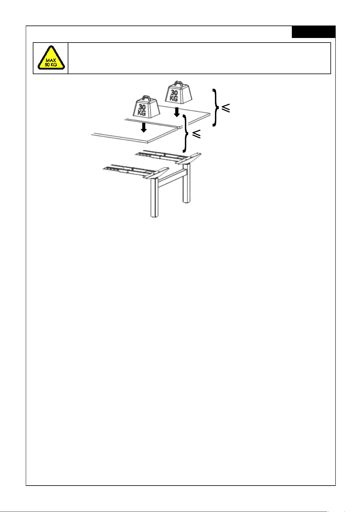
2.3 Maximum weight allowed on frame ...................................................................................................................8
2.4 Maximum weight allowed per column ...............................................................................................................9
2.5 Organizational measures......................................................................................................................................9
2.6 Informal safety measures......................................................................................................................................9
2.7 Note for those assembling the workstation.........................................................................................................9
2.8 Transport and assembly........................................................................................................................................9
2.9 Use of the workstation frame ...............................................................................................................................9
2.10 Specific dangers .................................................................................................................................................10
2.11 In an emergency.................................................................................................................................................10
2.12 Maintenance and upkeep ................................................................................................................................10
2.13 Cleaning ..............................................................................................................................................................10
2.14 Persistent risks .......................................................................................................................................................10
3ASSEMBLY..............................................................................................................................................................11
3.1 Pre-assembly of the Crossbars ...........................................................................................................................11
3.1.1 Recommended Top Sizes ..............................................................................................................................12
3.1.2 120cm Frame Set-Up Guide ............................................................................................................................12
3.2 Mounting the Back to Back Crossbar.......................................................................................................... 13-14
3.3 Mounting the Crossbar .......................................................................................................................................15
3.4 Mounting the Top Support..................................................................................................................................16
3.5 Adjustment of the Frame Width ........................................................................................................................16
3.6 Mounting the Spacer .........................................................................................................................................17
3.7 Mounting the Cable Clips ............................................................................................................................ 17-18
3.8 Connecting the Electrical Components...........................................................................................................19
3.9 Mounting the table top ......................................................................................................................................20
3.10 Mounting the Power Supply underneath the table top ..................................................................................20
3.11 Mounting Wire Clip........................................................................................................................................ 21-22
3.12 Clearance around the wall or moving parts 25mm of the table top ............................................................22
3.13 Frame Test without table top ....................................................................................................................... 23-24
4 CORRECT POSITION OF SEATS ..............................................................................................................................25
5 TECHNICAL SPECIFICATIONS ......................................................................................................................... 26-28
6 OPERATION AND INDICATORS.............................................................................................................................29
6.1 Indicators ..............................................................................................................................................................29
7 TROUBLESHOOTING ..............................................................................................................................................29
8 CUSTOMER SERVICE .............................................................................................................................................30
9 MANUFACTURER ...................................................................................................................................................30
10 RECYCLING ...........................................................................................................................................................30
10.1 Taking the workstation out of active duty ........................................................................................................30
10.2 Taking the workstation apart..............................................................................................................................30
10.3 Recycling .............................................................................................................................................................30
11 EU-DECLARATION OF CONFORMITY IN ANNEX II A..................................................................................... 31-32
English

3
Inhaltsverzeichnis
1ALLGEMEINESDER.................................................................................................................................................. 33
1.1 Stellenwert der Montage-/Bedienungsanleitung ............................................................................................ 33
1.2 Verwendungszweck........................................................................................................................................... 33
1.3 Unsachgemäße Verwendung........................................................................................................................... 33
1.4 Erdungsvorschrift................................................................................................................................................. 33
1.5 Gefahr ................................................................................................................................................................. 33
1.6 Lieferumfang.................................................................................................................................................. 34-35
2SICHERHEITSHINWEISE.......................................................................................................................................... 36
2.1 Symbol- und Hinweiserklärungen ...................................................................................................................... 36
2.2 Verwendete Symbole am Tischgestell.............................................................................................................. 36
2.3 Zulässiges Gesamtgewicht auf dem Tischgestell............................................................................................. 36
2.4 Zulässiges Gesamtgewicht pro Säule ............................................................................................................... 37
2.5 Organisatorische Maßnahmen ......................................................................................................................... 37
2.6 Empfohlene Sicherheitsmaßnahmen................................................................................................................ 37
2.7 Hinweise zur Montage........................................................................................................................................ 37
2.8 Transport und Montage ..................................................................................................................................... 37
2.9 Verwendung des Tischgestells........................................................................................................................... 37
2.10 Besondere Gefahrenstellen............................................................................................................................... 38
2.11 Hinweise für den Notfall ..................................................................................................................................... 38
2.12 Wartung und Instandhaltung ............................................................................................................................ 38
2.13 Reinigung ............................................................................................................................................................ 38
2.14 Restrisiken ............................................................................................................................................................ 38
3MONTAGE............................................................................................................................................................. 39
3.1 Vormontage der Traversen................................................................................................................................ 39
3.1.1 Empfohlene Tischplattenmaße...................................................................................................................... 39
3.1.2 Einstellung der Traversen auf 120cm ............................................................................................................. 40
3.2 Montage der Seitentraversen .................................................................................................................... 41-42
3.3 Montage der Traverse........................................................................................................................................ 43
3.4 Montage der Plattenträger ............................................................................................................................... 44
3.5 Einstellen der Gestellbreite ................................................................................................................................ 44
3.6 Montage des Abstandhalters............................................................................................................................ 45
3.7 Montage der Kabelhalterungen.................................................................................................................. 45-46
3.8 Anschließen der elektrischen Bauteile.............................................................................................................. 47
3.9 Montage der Tischplatte .................................................................................................................................. 48
3.10 Montage der Steuerung unter der Tischplatte ................................................................................................ 48
3.11 Montage der Kabelclips .............................................................................................................................. 49-50
3.12 Sicherheitsabstand zur Wand oder beweglichen Teilen von 25 mm um die Tischplatte ............................ 50
3.13 Funktionstest ohne Tischplatte ..................................................................................................................... 51-52
4 ERGONOMISCHE SITZEINSTELLUNG ..................................................................................................................... 53
5 TECHNISCHE DATEN ........................................................................................................................................54-56
6 BETRIEBSHINWEISE ................................................................................................................................................ 57
6.1 Fehlfunktionen...................................................................................................................................................... 57
7 FEHLERBEHEBUNG................................................................................................................................................. 57
8 KUNDENDIENST..................................................................................................................................................... 58
9 HERSTELLER............................................................................................................................................................ 58
10 ENTSORGUNG....................................................................................................................................................... 58
10.1 Außerbetriebnahme des Tischgestells .............................................................................................................. 58
10.2 Demontage des Tischgestells ........................................................................................................................... 58
10.3 Recycling............................................................................................................................................................. 58
11 EG-KONFORMITÄTSERKLÄRUNG NACH ANHANG II A .................................................................................59-60
Deutsch

4
Inhoudsopgave
1ALGEMEEN ............................................................................................................................................................61
1.1 Het belang van de montage–en bedieningshandleiding.............................................................................61
1.2 Beoogd gebruik ..................................................................................................................................................61
1.3 Onjuist gebruik.....................................................................................................................................................61
1.4 Aardingsinstructie................................................................................................................................................61
1.5 Gevaar.........................................................................................................................................................................61
1.6 Inhoud verpakking ........................................................................................................................................62-63
2VEILIGHEIDSINSTRUCTIES......................................................................................................................................64
2.1 Verklaring van symbolen en instructies .............................................................................................................64
2.2 Gebruikte symbolen op het frame....................................................................................................................64
2.3 Maximaal toegestaan gewicht op het frame ................................................................................................64
2.4 Maximaal toegestaan gewicht per kolom ......................................................................................................65
2.5 Organisatorische maatregelen .........................................................................................................................65
2.6 Informele veiligheidsmaatregelen.....................................................................................................................65
2.7 Vereisten aan de monteurs................................................................................................................................65
2.8 Transport en montage........................................................................................................................................65
2.9 Gebruik van het frame .......................................................................................................................................65
2.10 Specifieke gevaren.............................................................................................................................................66
2.11 Instructies voor noodgevallen............................................................................................................................66
2.12 Onderhoud en instandhouding.........................................................................................................................66
2.13 Reiniging ..............................................................................................................................................................66
2.14 Overige risico’s ....................................................................................................................................................66
3MONTAGE ......................................................................................................................................................................67
3.1 Voormontage van de crossbars........................................................................................................................67
3.1.1 Aanbevolen werkbladen ...............................................................................................................................67
3.1.2 120cm Frame instelling....................................................................................................................................68
3.2 Montage van de Back to Back Crossbar ...................................................................................................69-70
3.3 Montage van de voeten....................................................................................................................................71
3.4 Montage van de bladdragers...........................................................................................................................72
3.5 Instellen van de frame-breedte.........................................................................................................................72
3.6 Montage van de afstandhouders.....................................................................................................................73
3.7 Montage van de kabelclips..........................................................................................................................73-74
3.8 Aansluiten van de elektrische componenten..................................................................................................75
3.9 Montage van het werkblad...............................................................................................................................76
3.10 Montage van de handbediening .....................................................................................................................76
3.11 Montage van de kabelclips..........................................................................................................................77-78
3.12 Afstand van 25 mm tussen de muur of andere objecten en het werkblad..................................................78
3.13 Frame test zonder werklad............................................................................................................................79-80
4 CORRECTE ZITPOSITIE............................................................................................................................................81
5 TECHNISCHE SPECIFICATIES........................................................................................................................... 82-84
6 BEDIENING EN GEBRUIKSAANWIJZINGEN...........................................................................................................85
6.1 Gebruiksaanwijzingen........................................................................................................................................85
7 PROBLEEMOPLOSSINGEN ....................................................................................................................................85
8 KLANTENSERVICE..................................................................................................................................................86
9 FABRIKANT ............................................................................................................................................................86
10 RECYCLING...........................................................................................................................................................86
10.1 Buitenbedrijfstelling van het frame....................................................................................................................86
10.2 Demontage van het frame................................................................................................................................86
10.3 Recycling .............................................................................................................................................................86
11 EU-VERKLARING VAN OVEREENSTEMMING IN BIJLAGE II A........................................................................ 87-88
Nederlands

5
English
1 General
1.1 Local value of the assembly/Operating Manual
The guiding principle for safe use and trouble-free operation of this workstation frame is knowledge
of basic safety information and regulations. This assembly/operating manual contains the most im-
portant information needed for assembling and operating the workstation frame safely. This assem-
bly/operating manual, in particular the safety information contained herein, must be observed by
any person building the frame and working on the finished surface. More importantly, the rules and
regulations applying to accident prevention in the locality in which the workstation frame is to be
used must be observed at all times.
1.2 Intended use
The workstation frame must be used only as a height-adjustable workstation for sitting/standing use in
offices or other enclosed areas. The frame must be used for this purpose only. Any other use than the
above shall be deemed improper. The manufacturer can in no way be held liable for damage aris-
ing from improper use. This appliance can be used by children aged from 8 years and above and
persons with reduced physical, sensory or mental capabilities or lack of experience and knowledge
if they have been given supervision or instruction concerning use of the appliance in a safe way and
understand the hazards involved. Children should be supervised to ensure that they do not play with
the appliance, cleaning and user maintenance shall not be made by children without supervision.
Intended use shall also include:
• Observation of all information from the assembly/operating manual and
• Prohibition of any sort of addition to/conversion of the workstation.
1.3 Improper use
• Never use the workstation frame to lift people or loads.
• Do not exceed the maximum load of the workstation frame.
• Operate workstation only with power supply unit which is included in delivery.
1.4 Grounding Instruction (System with SMART/COMPACT Controller)
This workstation frame must be grounded. Connect this workstation frame
to a properly grounded outlet only. If it should malfunction or breakdown,
grounding provides a path of least resistance for electric current to re-
duce the risk of electric shock. This workstation frame is equipped with a
cord having a grounding plug like the plug illustrated in Figure 1. The plug
must be plugged into an appropriate outlet that is properly installed and
grounded in accordance with all local codes and ordinances.
This appliance incorporates an earth connection for functional purposes only.
For protective earth, the terminal is intended to connect with equipotential bonding of building
where the workstation frame is being setup. Terminals for the connection of external equipotential
bonding conductors shall allow the connection of conductors having nominal cross-sectional areas
of 2,5 mm2to 6 mm2.
1.5 Danger
Improper connection of the workstation frame grounding conductor can result in a risk of electric
shock. Check with a qualified electrician if you are in doubt as to whether the product is properly
grounded. Do not modify the plug provided with the product.
If the supply cord is damaged, it must be replaced by a special cord or assembly available from the
manufacturer or its service agent.
WARNING: Any changes or modifications not expressly approved by the manufacturer could void
the user’s authority to operate the equipment.

6
Items
4x
6
4x
3
1.6 Content Box
Assembly requires 2 people!
English
8x
4
2x
2
4x
7
2x
5
2x
9
2x
1
or or or or
or
or
** 2x
8
or
2x10

7
Mounting Hardware Kit
16x
A
M8x50
16x
B
M10x35 4.5x20
60x
C16x
D
M10x20
4x13 12x14
8x
12
4x11
English
** Control Unit 8(a) :
I. SMART-e-2-actiforce-EU : Input: 220-240Vac, 50-60Hz, 2.5A; Output: 288VA / 24V
II. SMART-e-2-actiforce-US : Input: 120Vac, 60Hz, 5A; Output: 216VA / 24V
** Control Unit 8(b) :
ControlForce 2 : Input: 100-120Vac, 60Hz, 5A max; Output: 24Vdc 9.2A
220-240Vac, 50Hz, 2A max; Output: 24Vdc 5A
Table : 24VDC, 4A
Tools
56x /

8
Example : All weight should be distributed evenly.
2 Safety Information
2.1 Symbols/Warnings
The assembly/operating manual uses the following terms and signs to indicate dangers:
This symbol indicates an immediate threatening situation for any person’s life or health.
Failure to adhere to such information may have serious consequences for health, or
could even result in life-threatening injury or death.
This symbol indicates important information. Failure to adhere to such information
could lead to damage to the workstation.
2.2 Symbols used on the workstation frame
Do not place objects or parts of the body under the workstation frame or between the
cross members. This could cause serious injury or even result in death.
English
80/120kg
> 80/120kg
80/120kg
20KG
20KG
2.3 Maximum weight allowed on frame
Do not exceed the maximum permitted load of
(a) 80 kg including table top (Smart-e-2)
(b) 120 kg including table top (ControlForce 2)
on the workstation frame. Avoid unbalanced load, distribute the weight
evenly, otherwise overload may occur. Overloading a frame may cause
breakage and close by individuals may suffer serious injuries as a conse-
quence.

9
2.4 Maximum weight allowed per column
2.5 Organizational measures
• The workstation frame can best be assembled by two people. Turning the frame, once the work
surface has been fitted, is a task in particular which requires two people!
2.6 Informal safety measures
• Keep the assembly/operating manual in the place where the workstation frame is used at all times.
• Make sure that all safety information on the table (see Section 2.2, Symbols used on the workstation
frame) is legible, replacing the same if necessary.
2.7 Note for those assembling the workstation
• The workstation must be assembled/worked on by persons over the age of 16.
• The persons referred to above must have read and understood the assembly/operating manual.
2.8 Transport and assembly
• The workstation frame must be moved by two persons only, and in such cases must be retracted.
• Do not drag or pull the workstation frame over the floor.
• Assemble the workstation frame with the supplied tools only. They are the only tools which ensure
that the screws can be tightened to the correct torque.
2.9 Use of the workstation frame
• Do not allow children to use the workstation frame unsupervised. Children may be unaware of the
dangers presented by the workstation frame. They would be in serious danger of injuring them-
selves, possibly even with fatal consequences. Further adjustment must then be impossible as a
safeguard against use by children.
• The workstation frame must only be used in appropriate areas.
• Do not use the workstation frame on an uneven surface. In such conditions it will not be steady.
• Never exceed the maximum load on the workstation frame.
Do not exceed the maximum permitted load of 50 kg (including table top) on a col-
umn. Overloading a frame may cause breakage and close by individuals may suffer
serious injuries as a consequence.
English
50 kg
50 kg

10
2.10 Specific dangers
• When adjusting the height of the frame there is danger of injury. Make sure that there is no-one
else in the immediate surroundings of the frame.
• When assembling the workstation frame, make sure there is ample space to avoid collisions (i.e.
inclination of roof, fixed objects, filing cabinets, waste-paper bins etc.) in all imaginable directions.
• Make sure there is ample space to avoid collisions if there are objects on the work surface such as
computers or computer peripherals.
• Make sure there is clearance of at least 25 mm from all other furniture, all around the workstation
frame.
2.11 In an emergency
• Stop using the workstation frame at once if you notice anything unusual (strange sounds etc.).
• Have the workstation frame repaired by specialists. Refrain from using the workstation frame until it
has been successfully repaired.
2.12 Maintenance and upkeep
• The workstation frame and its components are low-maintenance items and need no special regu-
lar maintenance.
• Do not perform any repairs on the work surface or other components yourself.
• Do not alter the construction of the work surface or its frame.
• Any faulty components removed must be replaced with new, original components from the manu-
facturer. Use only original replacement parts made by the manufacturer. Have any such work car-
ried out by a specialist, making reference to this Assembly/operating manual.
2.13 Cleaning
• Always unplug this workstation from the electrical outlet before cleaning.
• Dust the workstation frame once a week with a dry cloth.
• Clean the workstation frame with a damp cloth and a weak solution of cleaner once a fortnight.
2.14 Persistent risks
This workstation frame has been built to the state of the art and to recognized safety regulations.
Nonetheless, its use may constitute a risk to the health and safety of users or third parties, damage to
the workstation frame or to other items. The workstation frame must be used only:
• for the purpose for which it was intended.
• if it is completely safe to do so.
English

11
1
3 Assembly
Before attempting assembly, read the safety information in Section 2.
3.1 Pre-assembly of the Crossbars
Do not tighten the set screws on the crossbars yet !
English
4
4
B
6
To protect components and the floor from scratches, it is advisable to use a pad before
assembly. You can, for example, use the supplied cardboard by unfolding it.
Frame set-up Width / size table top Depth / size table top Table Top Thickness
110 cm 120 cm 80 cm 2.5 cm
130 cm 140 cm 80 cm 2.5 cm
150 cm 160 cm 80 cm 2.5 cm
170 cm 180 cm 80 cm 2.5 cm
3.1.1 Recommended Top Sizes

12
120 cm Frame set-up - offset the inner crossbar to 110 cm and 130 cm as shown in diagram
below.
3.1.2 120 cm Frame Set-Up Guide English
2 64
4

13
3.2 Mounting the Back to Back Crossbar English
4
3
2
7
7
1
5

14
English
5
6
D
11
11
* Repeat the same installation method for the subsequence unit.

15
English
7
A
3.3 Mounting the Crossbar
8
Secure the pre-assembled leg
from falling over.

16
B
B
B
B
B
B
B
B
English
3.4 Mounting the Top Support
10
3.5 Adjustment of the Frame Width
3
A
9
Adjust the frame into the desired width. Tighten the set screws on the crossbar
with Allen key M5.

17
English
3.6 Mounting the Spacers
3.7 Mounting the Cable Clips
12
11
12
14

18
English
13
14

19
14
3.8 Connecting the electrical components
Keep in mind that the desk which you are assembling is height adjustable.
The cables of the electrical components must be able to freely follow the
movement of the desk.
English
OPTIONAL
10
9
** 8
9
10
** 8

20
or
26x
C
26x
C
3.9 Mounting the table top
3.10 Mounting the power supply underneath the table top
15
English
OPTIONAL
2x
C 4x
C
2x
C
This manual suits for next models
4
Table of contents
Other Opendesk.ch Indoor Furnishing manuals
Popular Indoor Furnishing manuals by other brands

Dorel Asia
Dorel Asia DA8032 Instruction booklet

Riverside Furniture
Riverside Furniture Perspectives Leg Desk With Hutch 28031 Assembly instructions

Forte
Forte SNHT1531 Assembling Instruction

Möbelix
Möbelix ALMA OTMBK-2F Assembly instructions

modway
modway MOD-6303 quick start guide

Lightolier
Lightolier Lytecaster 1171 specification

Core Products
Core Products Corona CR 106 Assembly instructions

Ameriwood
Ameriwood 5959325K manual

Sable
Sable SA-HF005 user guide

Home Decorators Collection
Home Decorators Collection BRADSTONE JS-3419-A Use and care guide

Cooke & Lewis
Cooke & Lewis Indra 3663602527206 manual

Triarch
Triarch Indoor Lighting 31483 Assembly instructions