Opsis LD500 Operation manual

Opsis LD500 CEM System
Emitter and Receiver Units
ER060L, ER060AUTOL
Installation & User´s Guide
Release 1

Copyright © Opsis AB, Furulund, April 2006. Release 1.
Copyright
© Opsis AB. All rights reserved. This manual and the product described in it are copyrighted with
all rights reserved. No part of this publication may be reproduced, transmitted, transcribed, stored in
a retrieval system or translated into any language in any form by any means without the written per-
mission of Opsis AB. Information in this document is subject to change without notice.
Trademarks
OPSIS is a trademark owned by Opsis AB, Sweden. Other brands and product names are trademarks
or registered trademarks of their respective companies. Companies, names, and data used in exam-
ples herein are fictious unless otherwise noted.
Limited warranty
The warranty conditions of this product are described in the purchase agreement between the buyer
and the seller. However, a condition for any warranty is that the product is installed, operated and
maintained in accordance with the specifications and instructions issued by Opsis AB including but
not limited to this manual. This warranty is limited to replacement of defective material or documen-
tation supplied by Opsis AB and in no event shall Opsis AB or its suppliers be liable for any loss of
profit or any other commercial damage, including but not limited to direct or indirect, special, inci-
dental, contingent or consequential damages resulting from any defects on the product or its docu-
mentation including damages from downtime, loss of goodwill, damage to or replacement of
equipment or property.
Contact information
Adress Opsis AB
Box 244
SE-244 02 Furulund, Sweden
Telephone +46 46 72 25 00
Fax +46 46 72 25 01
Web-site http://www.opsis.se
E-mail info@opsis.se

Contents
1 Emitters and receivers ................................................................................. 1
1.1 The ER060L system ...................................................................................... 1
1.1.1 Technical specifications ................................................................................. 1
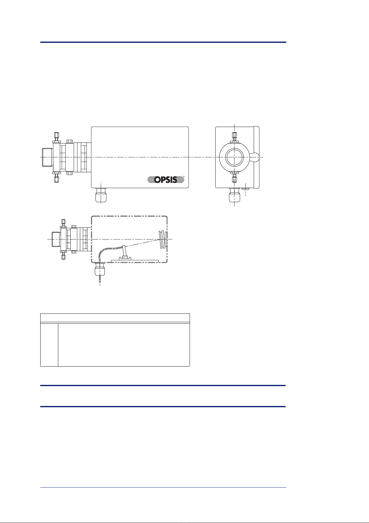
1.1.2 The emitter EM060L ..................................................................................... 2
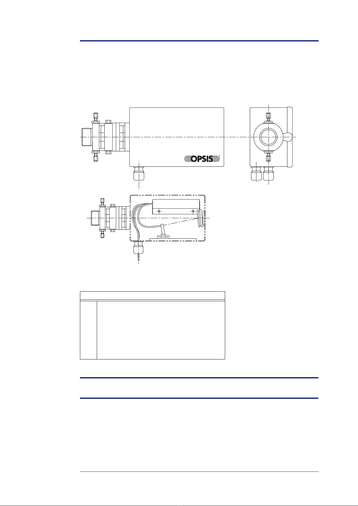
1.1.3 The receiver RE060L ..................................................................................... 3
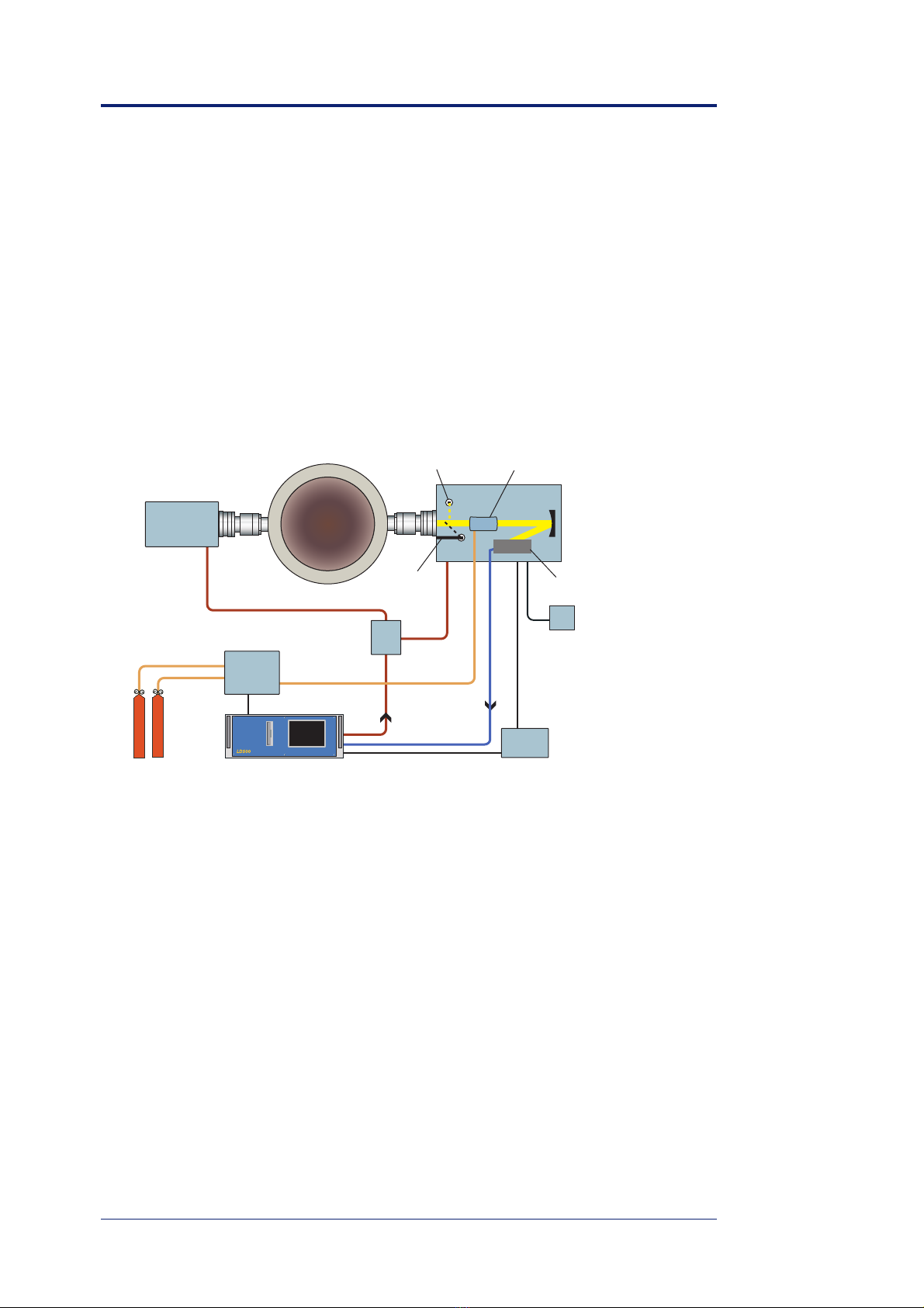
1.2 The ER060AUTOL system ........................................................................... 4
1.2.1 Technical specifications ................................................................................. 5
1.2.2 The receiver RE060AUTOL .......................................................................... 5
1.2.3 The calibration cell ........................................................................................ 5
1.3 Stack port connections - port installation kit ................................................. 6
2 LD500 CEM system accessories ................................................................. 7
2.1 The PM101L power supply ........................................................................... 7
2.2 The PW061 purge air cassette ....................................................................... 7
2.3 The optical fibres ........................................................................................... 8
3 CU004/007 Calibration unit ...................................................................... 11
3.1 Specifications ............................................................................................... 13
3.2 The control unit ............................................................................................ 13
3.3 Cables .......................................................................................................... 14
4 Safety precautions ...................................................................................... 17
4.1 Precautionary measures ............................................................................... 17
4.2 CU004/CU007 ............................................................................................. 18
5 Installation .................................................................................................. 19
5.1 Placement conditions for the emitter/receiver ............................................. 19
5.2 Placement conditions for the analyser ......................................................... 20
5.3 Flanges and PW061 cassettes ...................................................................... 20
5.4 Installation of ER060L ................................................................................ 21
5.5 Installation of ER060AUTOL ..................................................................... 21
5.5.1 Electrical connections .................................................................................. 22
5.5.2 Fiber optic connections ................................................................................ 22
6 Light adjustment kit LA060 ..................................................................... 23
6.1 Visually alignment of the transmitter and receiver with the LA060 ........... 24
6.2 Alignment of the transmitter and receiver with the LA060 with feedback
from the LD500 ........................................................................................... 24
6.3 Measure light throughput to ensure status of fibre or light transmitter
(version 1.2 and up) ..................................................................................... 25
6.4 Spare parts ................................................................................................... 25
7 Multiplexers and demultiplexers .............................................................. 27
7.1 Splitting multiplexers and demultiplexers ................................................... 27
7.1.1 Splitting multiplexers, MX10nL .................................................................. 28

7.1.2 Demultiplexers, MXn01L .............................................................................28
7.2 Switching multiplexers, SX10nL .................................................................28
7.2.1 Technical specification .................................................................................29
7.2.2 The DIP switches ..........................................................................................29
7.2.3 RS232 port configuration .............................................................................30
7.2.4 Software configuration .................................................................................30
7.2.5 Function test of the switch ............................................................................31
7.2.5.1 The function LED´s ......................................................................................31
8 Maintenance ................................................................................................33
8.1 Check list for preventive maintenance .........................................................33
8.2 Emitter and receiver .....................................................................................34
8.2.1 Cleaning the mirrors and windows ...............................................................34
8.3 Autocalibration units ....................................................................................34
9 Installation drawings ..................................................................................35
A Appendix: ER060AUTOL setup ..................................................................i
A.1 Enter the IO256 software .................................................................................i
A.2 Communication units using the IOMan protocol ............................................i
A.3 Load the settings from the IOMan modules ...................................................ii
A.4 Logg the calibration cell temperature .............................................................ii
A.5 Configuration of the CU007 ...........................................................................ii

1
Emitters and receivers 1
1.1 The ER060L system
The ER060L system consists of an emitter EM060L and a receiver RE060L. A power sup-
ply unit PM101L is needed to power the electronics in the receiver.
1.1.1 Technical specifications
ER060L system EM060L/RE060L
Dimensions (L ×W × H) 385 × 200 × 115 mm
Material aluminium/stainless steel
Weight (approx.) 7 kg
Window material quartz
diameter 50 mm
Mirror material quartz substrate
Ambient temperature -20 °C to +45 °C
Degree of protection IP54
Mounting 1 1/2” internally threaded pipe socket
Monitoring path length (recommended) 0.5 to 5 m
Purge air connections 6 mm
Note: If the ambient temperature is exceeding +45 °C it is necessary to cool the elec-
tronics in the receiver, e.g. by purging air through the receiver. The air should be clean
and free from oil and dust.
F
igure 1.1. The ER060L system.

Emitters and receivers
2
1.1.2 The emitter EM060L
The EM060L can transmit light over a path length of up to 5 meters. The light is led from
the laser head unit to the emitter via an optical fiber. The ending of the fiber is placed at
the focal point of a parabolic mirror. The light emitted by the transmitter is thus almost
parallel.
Main parts of the emitter EM060L
1 1 ½“ thread
2 Purged air inlet
3 Optical fibre inlet
4 Optical fibre
5 Mirror
Note: The coating on the mirror is very sensitive. It must not be touched or cleaned with
liquids.
F
igure 1.2. The emitter EM060L.
1
2
3
45

Emitters and receivers
3
1.1.3 The receiver RE060L
The RE060L unit contains a fibre holder and a mirror. The optical components are adjust-
able for the optimisation of the calibration light.
Main parts of the receiver RE060L
1 1 ½“ thread
2 Purged air inlet
3 Optical fibre inlet
4 Power inlet (±12 V)
5Detector
6Mirror
7 A/D converter
Note: The coating on the mirror is very sensitive. It must not be touched or cleaned with
liquids.
F
igure 1.3. The receiver RE060L.
1
2
34
56
7

Emitters and receivers
4
1.2 The ER060AUTOL system
ER060AUTOL is designed to be used for flue gas monitoring in stacks/ducts in combina-
tion with one Opsis LD500 analyzer. The ER060AUTOL consists of one emitter, EM060L
and one receiver RE060AUTOL.
In addition to a cross stack optical monitoring path, the ER060AUTOL provides automatic
calibration function. For fully automated calibration, a calibration unit CU007, must be
used in combination with the analyser and the ER060AUTOL.
The emitter and the receiver are units are mounted on purge air cassettes, PW061. The
PW061 is screwed on 1 1/2” pipe sockets. Port connections on stack are designed for 4”
ANSI flanges.
F
igure 1.4. The ER060AUTOL system designed for fully automated calibration.
LD500
Laser diode gas analyser
RE060AUTOL
receiver
EM060L
emitter
PM101L
power
supply
Fibre optic cable
Communication
cable
Calibration
cell
Fibre collimator
Calibration
gas
Mirror
Cell temperature
Calibration on/of
f
IOMan
Multiplexer
Calibration
unit
Detector

Emitters and receivers
5
1.2.1 Technical specifications
1.2.2 The receiver RE060AUTOL
The receiver is equipped with one parabolic mirror. The mirror collects and focus the re-
ceived light on to the detector, which is located at the focal point of the mirror. The light
will pass through a calibration cell on its way to the detector.
The light from the calibration lamp is focus in to a separate parabolic mirror. From the par-
abolic mirror the light is projected in two mirrors. After the second 45° angle mirror,
which is movable, the light enters the “normal “ path and is collected and focused in to the
optical fiber.
During a calibration the movable 45° angle mirror moves out and blocks the light from the
measurement path. By doing so, light from the calibration path will be collected in to the
optical fiber.
1.2.3 The calibration cell
The calibration cell mounted in the receiver makes it possible to perform not only zero
point calibrations, but automatic multi-point span calibrations for all gases being moni-
tored. The computer software supports up to three different calibration concentrations for
each gas and when connected via a CU007 auto-calibration unit, the calibrations are fully
automatic.
The inner diameter of the cell is 2” (53 mm) and the length is approximately 130mm. The
temperature controller, TC100, is located on the control unit.
The optical fiber is leading the captured light to the Opsis analyser unit, which by those
means can be protected from high temperature, dust, humidity etc.
ER060AUTOL system RE060AUTOL
Dimensions (L ×W × H) 720 × 310 × 330 mm
Material aluminium/stainless steel
Weight (approx.) 23 kg
Window material quartz
diameter 50 mm
Mirror material quartz substrate
Ambient temperature -20 °C to +45 °C
Degree of protection IP54
Mounting 1 1/2” internally threaded pipe socket
Monitoring path length (recommended) 0.5 to 5 m
Purge air connections 6 mm
Mirror voltage supply 230 VAC/115 VAC

Emitters and receivers
6
1.3 Stack port connections - port
installation kit
ER060AUTOL is a cross stack monitoring unit. Emitter and receiver are mounted on op-
posite sides, on 1 1/2” pipe socket connections. The recommended mount is a port kit sup-
plied by Opsis which includes set of 4” ANSI flanges that are attached to the stack/duct
walls.
In order to maximize system performance, it is critical that the flanges are properly
aligned. Proper alignment can be achieved by first installing the flange kit on one side, and
then by using the pipe insert for alignment of a long stick/ pipe inserted through the stack,
the exact aligned location for the second port can be found.
The pipe insert that extends in to the flue gas reduces turbulent effects on the monitoring
path length. The exact length of the pipe insert should be determined for each specific ap-
plication. As a guideline, the minimum length of the pipe insert is 1 ft, and the maximum 5
ft.
In raw gas application, i.e. before ESP / bag house particulate removals, it is recommended
that the total monitoring path length for the ER060AUTOL does not exceed 5.5 m or 18 ft.
F
igure 1.5. The receiver RE060AUTOL, side view.

7
LD500 CEM system accessories 2
2.1 The PM101L power supply
In order to operate the electronics in the receivers RE060L and RE060AUTOL, an Opsis
PM101L power supply unit is required. The PM101L unit provides a ±15 VDC and a +6
VDC signal to the RC101L detector card inside the receiver.
2.2 The PW061 purge air cassette
One PW061 purge air cassette is installed on the EM060L emitter and RE060/
RE060AUTOL receiver respectively. The purge air cassettes are used to connect the emit-
ter and receiver to the stack ports.
Each purge air cassette is equipped with two window holders, se figure 2.1. Each window
can be pulled out of its socket. Each window holder has a special guide so that it only can
be inserted one way. Windows may be cleaned with alcohol and paper tissue.
The purge air cassette consists of two sections that can be separated by loosening the two
lock bolts. Then, then section with the 1 1/2” pipe can be attached to the stack port, and the
units can easily be attached as well as de-attached from the stack in case service is needed.
The section that is attached to the stack port should be screwed in and secured with the
lock not. Note that the window handle should point straight up.
The purge air is connected on the 1/4” swagelock fittings. One 1/4” line with a minimum
flow of 1 scfm should be provided to each unit. A “T” coupling should split the flow in to
two 1/4” tubes and these should be connected to the fittings on the purge air cassette [2].
Technical specification: PM101L
Material (housing) PP/PVC
Dimensions (W ×H ×D) 800 ×200 ×130 mm
Weight 3.5 - 5.5 kg (depending on installed modules)
Voltage supply 240/115 VAC, 50-60 Hz
Power consumption < 100 W

LD500 CEM system accessories
8
Windows should be cleaned when:
• There are visible deposits of dust or liquid residuals, and
• Any signs of oil deposits on the windows (See purge air - instrument air quality)
2.3 The optical fibres
Three qualities of laser optical fibres are available for the LD500 system. The standard fi-
bre OF010 can be used in most applications. However, in applications where oxygen is
measured, the fibre OF005 should be used.
The optical communication fibre CF120 is used for data transmission.
Purge air cassette PW061
1 Window holder with removable window
2 Swagelok gas port, 6 mm
3 1 1/2” outer thread
NOTE: When servicing the units, only remove one window at a time. The windows pro-
tect the optical parts in the emitter and receiver, and at least one window must be in
place at all times to prevent damages to the units.
Note: During installation, complete the installation of the PW061 purge air unit,
including instrument air connections before proceeding to mount the emitter/receiver.
Fibre Specification
OF010-xxx Laser optical fibre, xxx = meters
OF005-xxx Laser optical fibre used with laser module LH515, xxx = meters
CF120-xxx Optical communication fibre, xxx = meters
F
igure 2.1. The purge air cassette PW061 should be inserted between each of the emitter
/
receiver, and the pipe flanges.

LD500 CEM system accessories
9
F
igure 2.2. Optical fibres, OF010 to the left and CF120 to the right.

LD500 CEM system accessories
10

11
CU004/007 Calibration unit 3
The calibration unit CU004/CU007 is designed for automatic calibration procedures using
Opsis gas monitoring systems. It can be used in several configurations, both for ambient
and for process applications:
• With emitter and receiver units ER060AUTO or ER062AUTO.
• With an ER070 or ER080/ER082 emitter/receiver with built-in calibration cell.
• Using a calibration path entirely separated from the measurement path.
• With a calibration cell in the measurement path (add-on calibration).
A serial port in the Opsis analyser is used to control the calibration unit. The operating
routines are included in the Opsis analyser software. Version number 7.10, or later, is re-
quired.
The model CU004 contains four valves and CU007 seven valves, one for each input line.
Thus, up to 4 or 7 different calibration gases including zero air supply can be connected.
Only one valve can be open at a time. If a multi-point span calibration is desired, two or
three different concentrations of each calibration gas have to be used. The output line from
the calibration unit is connected to the calibration cell in the Opsis gas monitoring system.
Light emitting diodes inside the calibration unit indicate if a valve is open. The outlet line
is provided with a flow meter and a flow regulator. The moveable fibre post in the ER070
and ER080 receivers and the moveable mirror in ER060AUTO/ER062AUTO and the
MB060A mirror box are also operated from the calibration unit.

CU004/007 Calibration unit
12
Main parts of an Opsis CEM system with automatic
calibrations
1 Emitter
2 Power supply
3 Receiver with built-in calibration cell
4 CU004/007 calibration unit
5 AR600 and AR650 analysers
6 Calibration gas cylinders
7 Opto-fibres
8 Gas line
F
igure 3.1. Example of an Opsis CEM system including the CU004/CU007 calibration
unit for automatic calibrations.
1
22
3
4
5
6
7
8

CU004/007 Calibration unit
13
3.1 Specifications
3.2 The control unit
The CU004/CU007 contains four/seven inlet valves, and a flow regulator at the outlet. The
CU004/CU007 is housed in a casing to be installed vertically on a wall, away from the gas
analyser. All gas connections must be made in well ventilated areas. Figure 3.2 shows the
internal of the CU004/CU007.
Control unit
Input voltage 120 VAC (± 10 %), 0.4 A
240 VAC (+6 %, -10 %), 0.2 A
Fuse ratings 1 ×2 A (120 V)
1 ×1 A (240 V)
Power requirement max. 45 W
Interface serial port in gas analyser, COM1 - COM7
Dimensions (L ×W ×H) 330 ×120 ×290 mm
Weight (approx.) 9 kg (20 lbs)
Operating temperature 0 °C to 30 °C (30 °F to 85 °F)
Degree of protection IP 30
Number of gas inlets 4 or 7 (CU004 and CU007 respectively)
Materials in valves stainless steel / viton
Gas connections Swagelok SS-400 series
Gas tube outer diameter 1/4"
Maximum inlet pressure 3.5 bar (50 psi)
Flow meter range 0 to 250 l/hour
Cable lengths (standard)
Analyser - CU004/CU007 2 metres (6 ft)
CU004/CU007 - receiver ordered fibre optic cable length + 1 metre (3 ft)

CU004/007 Calibration unit
14
The CU004/CU007 consists of the following main parts, compare figure 3.2:
The tube connectors are designed for 1/4" tube outer diameter. The connecting nuts should
thus be Swagelok SS-402-1.
3.3 Cables
Figure 3.3 shows the serial communication cable between the gas analyser and the control
unit. The signals sent through this cable controls the opening of the different valves, as
well as the switching between the measurement path and the calibration path, if applicable.
CU004/007 main parts
1 Cable inlets
2 Gas inlets from gas cylinders
3 Gas outlet to calibration cell
4 Electrically controlled valve
5 Flow meter
6 Flow regulator
7 Electronics board
8 Mains input
9 Fuse
10 Mains voltage selection
11 Connection for cable to fibre switch
12 Connection for serial communication cable from analyser
F
igure 3.2. The CU004/CU007 automatic calibration unit, here shown in the CU007 ver-
s
ion with seven valves.
123
4
5
6
7
8101112
9

CU004/007 Calibration unit
15
The cable is connected at position 12 in figure 3.2 as follows (connector seen as in this fig-
ure):
Figure 3.4 shows the cable between the calibration unit and the receiver/mirror box. It is to
be used in applications where the calibration path is an integrated part of the measurement
path, as is the case in an ER070 and an ER080 emitter/receiver, and in a configuration con-
sisting of an ER060/ER062 emitter/receiver and a mirror box MB60A. The fibre switch
option (and thus the cable) is not used in configurations with separate calibration paths or
for add-on calibrations using fixed calibration cells in front of the receiver.
The cable is connected at position 11 in figure 3.2 as follows (connector seen as in this fig-
ure):
The cable between the analyser and the calibration unit
left terminal black ground (GND)
mid terminal red receive (RX)
right terminal brown transmit (TX)
The cable between the calibration unit and the fibre switch motor
left terminal black 0 V (common)
mid terminal red monitoring path solenoid
right terminal brown calibration path solenoid
F
igure 3.3. The cable between the analyser and the calibration unit.
Connected
in the CU
Pin 2 RX
3 GX
7 GND DSUB 25p
female
F
igure 3.4. The cable between the calibration unit and the fibre switch motor.
Connected
in the CU
0 V black
Monitoring path brown
Calibration path red

CU004/007 Calibration unit
16
Table of contents