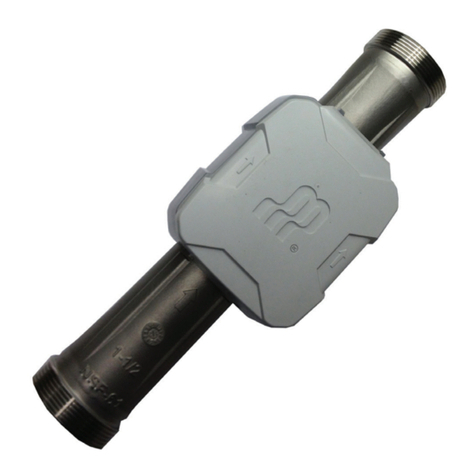
ERIKS ECON HCG 8370 User manual

Rev.1 Page 1 of 16
ECON HCG 8370
Self-powered Automatic
Contents Gauges
USER MANUAL
YARD :
HULL NUMBER :
IMO NUMBER :
YEAR :
ERIKS REF. :
CLASSIFICATION :
SHIPSNAME :
TYPE OF SHIP :
OWNER :

Rev.1 Page 2 of 16
CONTENTS
SECTION 1
1.1 Introduction
1.2 Description & Operation
1.3 Filling & Emptying the Tank
SECTION 2
2.1 Installation
2.2 Installing the transmitter
2.2.1 Installing the transmitter (external type)
2.2.2 Installing the transmitter (internal type)
2.3 Installing the capillary
2.4 Installing the indicator
SECTION 3
3.1 Specification
SECTION 4
4.1 Maintenance
4.1.1) Cleaning indicator face
4.1.2) Cleaning transmitter
4.1.2.1) External type transmitter
4.1.2.2) Internal type transmitter
SECTION 5
5.1 Malfunction & Remedy

Rev.1 Page 3 of 16
SECTION 6
6 Transport, packaging and storage
6.1 Transport
6.2 Packaging
6.3 Storage
SECTION 7
7.1 Ordering information
7.2 Available types and installation:
ERIKS bv reserves the right at any time and without notice to make specification changes, in
order to improve product design and performance, and as a consequence to revise manual
contents where necessary.
The information contained within this manual has been prepared with the cognisance of the
Health and Safety at Work, and is intended for use by trained personal conversant with this type
of equipment and normal engineering and safety practices.
Any application information included herein is intended for general guidance only. It is possible
to meet specific requirements of every application within the scope of this document.
IMPORTANT:
The instructions in this manual must be strictly followed.
The manufacturer declines all responsibility for any direct or indirect damage to property or
persons as well as for the consequence, for example, of lost production resulting from failure to
observe the instructions in this manual.

Rev.1 Page 4 of 16
SECTION 1
1.1 Introduction:
The HCG 8370 Series Hydrostatic tank Contents Gauge, ECON figure 8370, has long been
considered as one of the most reliable forms of tank gauging equipment available. The
instrument will indicate continuously the liquid contents of any shape of storage tank, and
display the data at considerable distance from the tank. The HCG 8370 Series can be supplied
with either an internal or external tank mounting transmitter plus a comprehensive range of
bulkhead plates or fittings, which allow the passage of capillary through oil and watertight
compartments in marine applications. In addition a special isolating maintenance valve assembly
is available for external transmitters.
Indicators have been designed to provide clear, easy to read data in one size, 160 mm diameter.
Dials are graduated in units to meet user’s requirements and are often marked with redial lines
to denote critical levels at various specific gravity’s.
The power required to operate the HCG 8370 Series hydrostatic tank contents gauge is derived
from the pressure exerted by the head of liquid within the tank (hydrostatic pressure). This
pressure is sensed by a stainless steel diaphragm set into the face of the transmitter and
conveyed by a length of capillary to a diaphragm within the indicator.
Deflection of the diaphragm within the indicator actuates a precision mechanism, which rotates a
pointer over a calibrated scale. The transmitting diaphragm, capillary and indicator diaphragm
together form a sealed system, prior to being charged with oxygen, is thoroughly examined for
leaks.
Not attempt should be made to disconnect the capillary from the instrument, except for mounting
if necessary.
1.2 Description & Operation
A flexible metallic diaphragm contained in the transmitter is so arranged that its internal volume
is connected, by capillary tubing, to a diaphragm within the indicator. The total volume contained
by these two diaphragms and the capillary tubing is charged with an gas and sealed. When the
transmitter is connected or installed in the tank the transmitting diaphragm is exposed to the
pressure exerted by the head of liquid above the transmitter‘s datum. This pressure adjusts the
position of the diaphragm and causes an equal pressure to be imparted to the gas within the
system, such pressure being conveyed by the capillary tubing to the indicator. With the increase
in pressure this diaphragm distends and causes a precision mechanism to rotate the pointer
over the calibrated scale.
1.3 Filling & Emptying the Tank:
The following points should be borne in mind when filling and emptying the tank.
1. The tank must be kept fully vented to atmosphere.
2. Overload must be kept within the limits stated when the instrument was ordered.
3 The temperature of the liquid must not be widely divergent from that specified.
(The gauge is fully compensated for all normal ambient temperature changes)

Rev.1 Page 5 of 16
SECTION 2
2.1 Installation:
WARNING:
Incorrect use of the gauge system can cause damage and injuries. Under this Directive, the user
ensures that the gauge system is installed and used in such way that hazards are eliminated to
a maximum extent.
Safety instructions:
The appropriate national safety regulations must be observed when mounting and operating
these gauge systems. Serious injuries and or damage can occur should the appropriate
regulations not be observed. Only appropriately qualified persons should work on these
instruments.
To insure long trouble-free service, considerable care must be exercised during installation to
avoid damage to the capillary tubing. Whenever possible, installation should commence by fixing

Rev.1 Page 6 of 16
the indicator in position, so that where is less risk of the instrument being damaged when the
capillary in unrolled. With the internal transmitter it may practical to disconnect the capillary
tubing from the indicator or the bulkhead fitting.
In such a case the disconnected coupling of the capillary should be adequately protected from
mechanical damage when routing the capillary. The capillary should be carefully unrolled along
the route to be followed. Do not pull the coil apart and attempt to correct the spring-like effect by
pulling with either the indicator or transmitter.
The following points should be noted:
1) Protect the transmitter against the ingress of foreign matter. Sharp particles of grit or dust can
puncture the diaphragm.
2) Use a correctly sized spanner to tighten connections.
3) Never twist the indicator or transmitter to tighten connections.
4) DO NOT drag the indicator, capillary and / or transmitter over sharp edges
5) DO NOT swing the indicator and / or transmitter by the capillary.
Transmitters from DN100 and bigger are provided with a special lifting handle on the transmitter.
The level of the indicator head in relation to the transmitter unit in no way affects the reading of
the gauge.
The following points should be checked against the original questionnaire or instructions sent to
us when ordering:
1) Is the liquid the same specific gravity as that given to us at the time of ordering?
Have the original dimensions been altered?
2) Has the position of the transmitter in relation to the tank bottom been altered?
3) Has the operating temperature been altered?
2.2) Installing of the transmitter
Different possibilities of installation are possible, depending of the tank type, available space etc.
There are two ways of installation:
- Side mounting on the tank wall, flanged or screwed.
- Inside the tank (submersed), vertical or horizontal with a mounting bracket.
2.2.1 Installing the transmitter (external type)
The HCG 8370 transmitter is bolted to a previously prepared steel flange (customer supply) on
the side of the tank, whose centre-line from the bottom of the tank must be in accordance with
the figures given by order.

Rev.1 Page 7 of 16
Care must be taken to ensure that the flange has a machined face, and that any weld does not
foul the transmitter.
The diaphragm detects the hydrostatic head of the tank contents through a full bored hole:
THE HOLE MUST BE DRILLED BEFORE FITTING THE TRANSMITTER.
The transmitter may be fitted using an isolating valve. This enables the transmitter to be
removed without draining the tank.
Take care tank is empty and not filled in the meantime if capillary will be connected after
fitting of the diaphragm.
2.2.2 Installing the transmitter (internal type)
The transmitter is mounted horizontally or vertical on an internal bracket with the diaphragm
facing downward at a pre-determined height from the tank bottom, which must be in accordance
with the figure given by order.
A connecting capillary protected by a stainless steel flexible tubing runs inside the tank to a
bulkhead flange or other bulkhead fitting on the side or top of the tank. The capillary passes
through the bulkhead flange or bulkhead fitting. Stainless steel protected capillary is used
between this bulkhead flange or bulkhead fitting and the indicator. All capillary must be
adequately supported particularly inside the tank.
Take care tank is empty and not filled in the meantime, if capillary will be connected after
fitting of the diaphragm and bulkhead flange or fitting.
Care should be taken to avoid physical impact of solid objects onto the transmitter face. Care
should be taken, particularly in the case of the submersible mounted transmitter when lowering
into the tank that solid objects resting on the bottom of the tank are not in direct contact with the
transmitter face, as this will cause large errors.
The transmitter should be installed well away from tank inlets, pumps and areas of turbulence or
pressure surges, as there can cause errors or even damage transmitter.
CAUTION:
- If any kind of work are carried out inside the tank it is necessary to protect the diaphragm of the
transmitter against chocks, sandblasting , painting, etc.
2.3 Installing the capillary
Gauges are supplied fitted with a specified length of SS armour covered capillary.
All capillary must be adequately supported.
Support the capillary (internal or external to the tank) in cable tray wherever possible and secure
at intervals of 300 mm with cleats.
Provide cleats at the beginning and completion of every band.

Rev.1 Page 8 of 16
Although the capillary stainless steel covering is of a robust quality, provide a shield where
mechanical damage is likely to occur.
Capillary bends should not have a radius of less than 5 cm.
Avoid routing the capillary where it could be used as a “pipe on which to hang objects”.
Do check capillary armoured cover for signs of damage (cuts, weld spatter, burns etc.)
particularly inside the tank area. Damage to the armour cover can means damaged capillary.
This may affects the reading of the gauge.
DO NOT fix capillary alongside pipes with a temperature which exceed 50°C.
When connecting the capillary to the transmitter or indicator take care new seals are used.
A set of spare seals is tied to the coupling.
NOTE:
- During disassembly capillary, check that the system is no longer under pressure, tank empty or
no pressure on transmitter.
- During assembly capillary, check that the system is not under pressure, tank empty or no
pressure on transmitter.
2.4 Installing the indicator
The indicator must be mounted in compliance with standard practice.
The indicator is provided with a back plate for wall mounting.
The indicator must not be subjected to:
-Mechanical shocks
-Vibrations
-Temperatures greater or less than operating temperatures
SECTION 3
3.1 Specifications
3.1.1 Operational Data
Maximum Error
At reference conditions the maximum error will not exceed ± 1.6% of full scale deflection.
Operating Temperature
As standard : -20°C to +50°C (depending on liquid)
Ranges within : -50°C to +100°C to order
Overload
Normally 25% above maximum range but protection also given to 2 bar.
3.1.2. Construction Data
Transmitter
Standard transmitters comprise a stainless steel diaphragm, welded into a stainless steel plate,
size depending on type.

Rev.1 Page 9 of 16
Tank connection : Depending on type
Material flange : AISI316/1.4401
Material diaphragm : AISI316/1.4401
Capillary lengths
Maximum length 10 metre.
Longer is possible but will slow down the indication.
Capillary material : red copper with SS armoured cover
Material armoured cover : AISI304/1.4301
Indicators
Indicator size : Ø 160 mm
Indicator mounting : back flange for wall mounting
Material indicator housing : AISI304/1.4301
Protection class indicator : IP-45
Capillary connection indicator : Bottom side
Indicator scale division : m³ according tank volume table
Indication : By pointer, black, on white background with white figures
Material indicator window : Mineral glass 4 mm
SECTION 4
4.1 Maintenance
Providing that the instrument has been installed with care, it will give many years of trouble- free
service.
Maintenance operations are limited to periodical cleaning of the indicator face and ensuring that
the transmitter is kept clear of sludge or congealed liquid.
4.1.1) Cleaning indicator face
Maintenance task procedure (and safety procedures):
- Clean the indicator face with a soft cloth with a glass-cleaner or soapy water.
- Dry the indicator face with a soft cloth.
- Do not use a dirty or greasy cloth and/ or aggressive cleaner.
Average interval between maintenance task:
- Clean indicator face on regular times, ones a month, and when it is too dirty to do a right
reading.
Average time required to perform a task:
- Cleaning of the indicator face will takes max. 5 minutes.
Required spares, tools, maintenance resources:
- Required spares : NON
- Required tools : NON
- Maintenance resources : Glass cleaner, soft cloth.
4.1.2) Cleaning transmitter

Rev.1 Page 10 of 16
4.1.2.1) External type transmitter
When external type transmitter is employed on an installation viscous fuel, the transmitter should
be heavily logged and, if possible, fitted with an electrical tracer. Alternatively, the transmitter
should be positioned close to outflow heaters etc.
Where water is being measured and the tank is exposed to the weather, normal winter
precautions must be observed to prevent the transmitter being damaged by the formation of ice
around the diaphragm.
To cleanse the congealed fluid or sludge from a transmitter it must be removed from the tank so
obviously the tank must be drained first, unless there is an isolating valve fitted.
The following procedure should be adopted by cleaning:
a) Close isolating valve, if fitted, or empty tank.
b) Remove the transmitter from the tank by unscrewing the bolts or ¾” BSP union (depending on
type of connection).
As sludge deposits may be present in the isolating valve and / or transmitter connection, it is
advisable to place a container directly beneath the isolating valve and / or transmitter to catch
the small quantity of fluid which may drip from the isolating valve and / or transmitter.
c) Place the transmitter in a container of non-corrosive solvent compatible with liquid being
measured. For example, for fuel oils use paraffin.
ON NO ACCOUNT INSERT A PROBE INTO THE TRANSMITTER CONNECTION OR MAKE
ANY ATTEMPT TO DISMANTLE THE TRANSMITTER OR DISCONNECT THE CAPILLARY.
c) Gently agitate the transmitter in the solvent until the congealed liquid is seen to be leaving the
transmitter connection. To assist in dislodging stubborn deposits a small quantity of solvent may
be poured into the transmitter connection and, with the connection sealed for example by a
hand, the transmitter gently shaken.
Continue with cleaning operations until all sludge has been expelled.
Before re-connecting the transmitter to the tank lightly open de isolating valve to ensure that
heavy sludge has not accumulated around the valve and would prevent free flow of liquid into
the transmitter.
Should it appear that the tank contains an excessive quantity of sludge the assistance of the
local fuel distributor should be sought.
Average interval between maintenance task:
- Clean the transmitter in the tank at least every survey of the tank.
Average time required to perform a task:
- Cleaning of the transmitter will takes approx. 30 minutes.
Required spares, tools, maintenance resources:
- Required spares : NON
- Required tools : Spanner, size depending on type of tank connection
- Maintenance resources : Container
: No-corrosive solvent

Rev.1 Page 11 of 16
4.1.2.2) Internal type transmitter
When internal type transmitter is employed on an installation viscous fuel, the transmitter should
be heavily logged and, if possible, fitted with an electrical tracer. Alternatively, the transmitter
should be positioned close to outflow heaters etc.
Where water is being measured and the tank is exposed to the weather, normal winter
precautions must be observed to prevent the transmitter being damaged by the formation of ice
around the diaphragm.
To cleanse the congealed fluid or sludge from a transmitter it must be removed from the tank so
obviously the tank must be drained first, made gas free and cleaned for entering.
The following procedure should be adopted by cleaning:
a) Make tank empty.
b) Make tank gas free.
c) Clean the tank.
b) Remove the transmitter from its mounting bracket in the tank by unscrewing the two M16
bolts.
e) Place the transmitter in a container with non-corrosive solvent compatible with liquid being
measured. For example, for fuel oils use paraffin.
ON NO ACCOUNT INSERT A PROBE (SCREW DRIVER FOR EXAMPLE) INTO THE
TRANSMITTER OR MAKE ANY ATTEMPT TO DISMANTLE THE TRANSMITTER OR
DISCONNECT THE CAPILLARY.
f) Gently agitate the transmitter in the solvent until the congealed liquid is seen to be leaving the
transmitter. To assist in dislodging stubborn deposits a small quantity of solvent may be poured
into the transmitter, the transmitter gently shaken.
g) Continue with cleaning operations until all sludge has been expelled.
Should it appear that the tank contains an excessive quantity of sludge the assistance of the
local fuel distributor should be sought.
Average interval between maintenance task:
- Clean the transmitter in the tank at least every survey of the tank.
Average time required to perform a task:
- Cleaning of the transmitter will takes approx. 30 minutes.
- Complete operation, emptying tank, making gas free, cleaning of the tank and cleaning of
transmitter
will take approx. 2 days.
Required spares, tools, maintenance resources:
- Required spares : NON
- Required tools : Spanner M16
- Maintenance resources : Container
: No-corrosive solvent

Rev.1 Page 12 of 16
MAINTENANCE, VERIFICATION OR RE-CALIBRATION MUST BE CARRIED OUT BY
PERSONNEL APPROVED BY THE CONSTRUCTOR AND USING SUITABLE EQUIPMENT.
Whenever a service visit is required, please quote the tank name of the instrument.
SECTION 5
5.1 Malfunction and Remedy
INFORMATION:
Before you take any action by a misreading take care of the following:
- The adjustment of the gauge is calculated with the offset of the transmitter and the specific
gravity of the liquid.
Before comparing the level, check the offset of the transmitter and the specific gravity of the
liquid in the tank.
If it is different, you may have a significant error.
- The indication is without any Trim and / or List correction. This means if the manual sounding
pipe is not located close to the transmitter, you may have a significant difference between
manual sounding and read-out.
- For tanks with a shape, check if the manual sounding pipe is not bent or if the end of the pipe
is not installed above or below the transmitter position. If “yes”: you have to compare the volume
in according with the manual sounding tables.
5.1.1 Symptoms:
a) The gauge indicates a value above that which is known to be in the tank.
b) The gauge indicates a value below that which is known to be in the tank.
c) The pointer gradually returns to zero.
d) The pointer shows no movement with variation in the liquid level.
e) The pointer starts to make a second sweep of the scale.
f) Indication is erratic and unstable –varies with temperature.
5.1.2 Remedy:
a) 1. Check that tank dimensions (including slope and direction relative to gauge transmitter,
specific gravity and position of transmitter) are in accordance with information given to
ERIKS bv at the time of order.
Providing that dimensions are changed the instrument has to be modified.
Copies of the tank calculation to which the gauge was originally manufactured are
available.
On receipt of the calculations they should be compared with the makers calculations. If
the figures agree and a constant error is evident, it is possible to reset the pointer to the
correct figure. A reset should be made as near as possible to half-scale deflection.
Further check readings should be taken at other points on the scale. If the instrument is
not within the accuracy guaranteed by ERIKS bv then it should be returned
to ERIKS bv for attention.

Rev.1 Page 13 of 16
2. Check that the gauge transmitter is not choked with congealed liquid or sludge.
Clean transmitter.
3. Check that the tank’s ventilation is not blocked. If a gauge shows a normal reading when
the manhole cover is released, the vent pipe should receive attention.
4 Check that the pointer is not touching the dial or indicator face.
b) 1. Check as in a) 1. Above.
2. Check that the capillary tubing has not been damaged or fractured. Should the capillary
be damaged in any way, the instrument must be returned to our Works. Our service
engineers cannot rectify such damage on site.
3. Check as in a) 2. Above.
4. Check that the gauge has not been calibrated from a datum other than tank bottom.
Your dipstick will almost certainly be calibrated from the bottom of the tank. Dials
commencing at zero will invariable from the centre line of the transmitter or feed line
from the tank, ignoring falling below this level.
5. Check that the transmitter has been connected to the feed pipe from the tank and is
being subjected to loss in pressure due to flow of liquid or the effects of suction pumps
that may be in the circuit.
c) 1. Check as in b) 2.
2. Return gauge to our Service Department or ask for the assistance of one of our
engineers.
3. Check as in b) 5..
d) 1. Check as in a) 2.
2. Check as in a) 4.
3. Return gauge to our Service Department or ask for the assistance of one of our
engineers.
e) 1. Check as in a) 1.
2. Check as in a) 3
f) 1. Check as in a) 2.
2. Return gauge to our Service Department or ask for the assistance of one of our
Service Engineers.
NOTE:
- During disassembly capillary, check that the system is no longer under pressure, tank empty or
no pressure on transmitter.
- During assembly capillary, check that the system is not under pressure, tank empty or no
pressure on transmitter.

Rev.1 Page 14 of 16
- Use by assembly of capillary new seals, spare seals are tied to the couplings.
SECTION 6
6). Transport, packaging and storage
6.1) Transport
Check the instrument for any damage that may have been caused by transport.
Obvious damage must be reported immediately.
Damage through improper transport;
- With improper transport, a high level of damage to property can occur. When unloading packed
goods upon delivery as well as during internal transport, proceed carefully and observe the
symbols on the packaging.
With internal transport, observe the instructions in chapter 1.2 “Packaging and storage”.
6.2) Packaging
Do not remove packaging until just before mounting. Keep the packaging, especially the
diaphragm protection (if available).
This will provide optimum protection during transport (e.g. cleaning, change in installation site,
sending for repair).
- With improper unpacking, a high level of damage to property can occur.
- Damage to the diaphragm during unpacking. Avoid touching the diaphragm after removing the
diaphragm protection. Impermissible mechanical loading (e.g. pressing the diaphragm) can
result in measuring deviations or even in the complete failure of the measuring instrument.
- To protect the pressure gauges from mechanical damage keep them in the original packaging
until installation.
6.3) Storage
Permissible conditions at the place of storage:
- Storage temperature: -40 ... +70 °C
Avoid the following influence:
- Not in the open air
- Not exposed to corrosive media
- Mechanical vibration shock (putting it down hard)
- Protect the instrument from humidity and dust.

Rev.1 Page 15 of 16
SECTION 7
7.1 Ordering information:
If you want to other new instruments (only supply of complete instruments is possible) please
mention the following information on your order:
-Vessels name
-IMO number
-New building number vessel
-Ships owner
-Yard vessel built of
-Serial number of the old instrument, to be find on indicator scale plate above ECON logo
-Tank name mentioned on scale plate.
If that information cannot be found or is unreadable you can give the following information:
-Size of the transmitter flange, or type of transmitter
-Tank name
-Kind of liquid in the tanks
-S.G. of the liquid in the tanks
-Temperature of the liquid in the tanks
-Distance between diaphragm and tank bottom (offset)
-Length of the capillary between diaphragm and indicator
-A picture from the indicator and transmitter will give lot information.
Serial number
Tank name

Rev.1 Page 16 of 16
7.2 Available types and installation:
Table of contents
