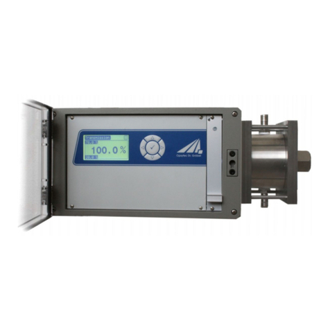
Opsytec Dr. Grobel RM-32 User manual

Radiometer
RM-32
Operating instructions
Version: 1.4
Opsytec Dr. Gröbel GmbH
Am Hardtwald 6-8
D-76275 Ettlingen
Phone: +49(0)7243 / 9 47 83-50
Fax: +49(0)7243/ 9 47 83-
65info@opsytec.de

1 Table of Contents 2
1 Table of Contents
1Table of contents ................................................................................................................. 2
2Change history..................................................................................................................... 2
3Symbol overview................................................................................................................. 2
4Foreword.............................................................................................................................. 3
5General description.............................................................................................................. 4
6Settings and connections ..................................................................................................... 5
7Programming the panelmeter............................................................................................... 7
8Integrated program routines................................................................................................. 8
9Communication RS232, RS485 or USB............................................................................ 11
10 Programming RS232, RS485 or USB ............................................................................... 13
11 Sub-D RS232 Adapter ....................................................................................................... 15
12 Technical data.................................................................................................................... 16
13 Radiation protection .......................................................................................................... 16
2 Change history
Version
Modified from
Changes
1.1
Paravia
div. adjustments
1.2
Paravia
enhanced communication
1.3
Paravia
Advanced preset RS232
1.4
Small
RS232 adapter board inserted
3 Symbol overview
Significance:
Failure to follow the above instruction may result in
injury to the user.
Significance:
Failure to follow these instructions may
result in
damage to the unit.
Significance:
Instruction is to be observed for regular opera-
tion.

4 Foreword 3
4 Foreword
Dear Customer,
You have decided to purchase a high-quality precision UV measuring device.
The operation is simple, please follow exactly our explanations in the enclosed operat-
ing instructions, the measuring accuracy is then guaranteed.
In order to guarantee this measurement accuracy over a longer period of use, we rec-
ommend that you send your sensor to us for inspection every 12 months.
We recalibrate the sensor, if necessary we repair it. A short time later, your measuring
equipment will be available again in mint condition with test certificate.
At the same time, we will keep you regularly informed about the latest UV measure-
ment possibilities.
As you can see, customer service is still very important to us. We are happy to provide
you with technical information and advice at any time.
Opsytec Dr. Gröbel GmbH

5 General description 4
5 General description
The mains operated display unit RM-32 is designed for continuous monitoring of lamps
mainly UV lamps. In addition to lamp monitoring, absorption, transmission and reflection
measurements can also be carried out.
The display is digital (3 1/2 digits) in W/m2. Two light-emitting diodes (SP1, SP2) indi-
cate the status in relation to two preselectable thresholds. Two relays with switching
contacts are activated simultaneously. The relay functions can be triggered with a time
delay.
The device is programmable and can control numerous parameters of the measure-
ment process with its integrated measurement routines.
Optional USB, RS-232 or RS-485 interface is available.
Connect the supplied sensor to input 2 and 4. Only use the sensor type for which you
ordered the device. Connecting a different sensor type can lead to malfunctions. Follow
the instructions for the sensor carefully.

6 Settings and connections 5
6 Settings and connections
2.1. Controls and display
The indicator lights up when the RM-32 is connected to mains voltage.
Fig. 1: Control element RM32
SP1: When the button is pressed, the SP1 pre-alarm setpoint is dis-
played.
SP2: When the button is pressed, the SP2 alarm setpoint is displayed.

6 Settings and connections 6
2.2 Terminal connection assignment
Fig. 2: Terminal assignment of the terminals
Relay SP2: potential-free switching output, alarm
Relay SP1: potential-free switching output, pre-alarm
PIN 9-11: RS232 output (optional via external board)
Connect the circuit board with the sockets pointing downwards
PIN 12: + 24 V, wire colour white
PIN 13: 0V, wire colour brown
230V Mains: Mains voltage connection
Sensors with voltage output 0-10 V must be connected to the RM32 as follows:
Input 2: Sensor signal High , wire color black
Input 4: Sensor signal low, wire colour grey (GND for measurement)
24V output: galvanically isolated supply voltage 24V DC (max. 30 mA)
Sensors with current output 4-20mA must be connected to the RM32 as follows:
Brown / white at terminal number 12 (+ 24V)
Blue /black at terminal number 2 (input)
2.3 Locking the keypad
There is a jumper on the motherboard that can be placed through the hole in the side
of the case. When the jumper is open, the keyboard is locked. An input of commands
is then no longer possible.

7 Programming of the installation instrument 7
7 Programming of the installation instrument
The programmable panelmeter RM-32 can control numerous parameters of the
measuring sequence with its integrated measuring routines. New values are set via
the keyboard.
This way, the desired measuring routine can be selected at the RM-32:
Press MOD button MOD
Select routine with the arrow key
Confirm with MOD button MOD
Change values of the respective measuring routine:
Set desired value with arrow key
Select next position with back arrow key
Set desired value with arrow key,....
When the desired value is entered,
Accept the value with the MOD key MOD
The device now operates in the measuring mode again.
Changes to the setting can greatly falsify the
measurement result. Pay attention to the settings
on delivery.
1. Error messages
If the measuring signal exceeds or falls below the permissible value of the input
range, the following error message appears on the LED display:
"oooo" = measuring range is exceeded
"uuuu" = measuring range is undershot

8 Integrated program routines 8
8 Integrated program routines
Routine 1-5: not occupied
Routine 6: Set decimal point
The position of the decimal point on the LED display is set with
000: no decimal point (maximum display: 1999)
001: 1.000
002: 19.99
003: 199.9
dialed.
Changes to routine 6 can strongly falsify the
measurement result. Only change the settings of
the device after consulting the manufacturer.
Routine 7: Set switching point SP1 pre-alarm
With this function the threshold SP1 pre-alarm can be set in W/m.2The maximum val-
ue is 1000.
Routine 8: Activate setpoint SP1 pre-alarm
This function routine can be used to switch the SP1 pre-alarm setpoint on and off. In
the last digit
000: inactive or
001: active
set.
Routine 9: Set switching point SP2 alarm
With this function the threshold SP2 alarm can be set in W/m.2The maximum value is
1000.
Routine 10: Activate setpoint SP2 alarm
This function routine can be used to switch the SP2 Alarm setpoint on and off. In the
last digit
000: inactive or
001: active
set.

8 Integrated program routines 9
Routine 11: Switching point hysteresis SP1 Pre-alarm
The hysteresis is set in W/m.2
Routine 12: Switching point hysteresis SP2 Alarm
The hysteresis is set in W/m.2
Routine 15: Set relay function of SP1 pre-alarm
Routine 16: Set relay function of SP2 alarm
Each relay can act as a normally closed or normally open contact when the respective
switching point is reached.
001: Opener
000: N/O contact
NC contact = the relay opens the circuit when the switching point is reached.
Normally open = the relay closes the circuit when the switching point is reached.
Routine 17: Timed pickup or dropout delay of SP1 pre-alarm
When the threshold value is reached, the relay function is triggered with a time delay.
The time delay is proportional to the number of measuring cycles (max. 1999 cycles).
The measuring rate is 2.5 measurements per second.
Number of measuring cycles: time delay
Routine 18: Timed on-delay or off-delay of SP2 alarm
When the threshold value is reached, the relay function is triggered with a time delay.
The time delay is proportional to the number of measuring cycles (max. 1999 cycles).
The measuring rate is 2.5 measurements per second.
Number of measuring cycles: time delay
Routine 19: Querying the maximum measured value
The maximum value is continuously determined and stored since the last RESET. The
reset is carried out when the min. or max. value is displayed by pressing the SP1 pre-
alarm and SP2 alarm keys simultaneously for 3 seconds.

8 Integrated program routines 10
Routine 20: Querying the minimum measured value
The minimum value is continuously determined and stored since the last RESET. The
reset is carried out when the min. or max. value is displayed by pressing the SP1 pre-
alarm and SP2 alarm keys simultaneously for 3 seconds.
Routine 21: Last digit round up/down
The value for the last decimal place can be rounded. The following settings are possi-
ble:
000: last digit is set to 0
001: last digit is displayed
002: last digit is set to 0 / 2 / 4 / 6 / 8
005: last digit is set to 0 / 5
Routine 22: Number of measurements for averaging
The display shows the average value.
Setting
000: no averaging
002: 2 measurements for average
003: 3 measurements for average
...
1999: 1999 measurements for average
Routine 23: not occupied
Default setting: "000" must be maintained.
Routine 24 and 25: not occupied
Routine 26: Divider factor of the measured value by 10
Setting
000: no divisor factor
001: Value is divided by 10

9 Communication RS232, RS485 or USB 11
9 Communication RS232, RS485 or USB
Data transmission of the measured values of the SPE670 via serial interface.
Routine 25: Activate/deactivate the serial interface
Routine 27: Setting the baud rate of the serial interface
Routine 34: Transmission cycles for the serial interface
Jumper JP4 can be used to bypass the enable/disable by routine 25, the interface is
then always active. The cycle setting of routine 34 remains valid. Thus, the interface
can still be deactivated by a transmission cycle of 0.
The individual characters are transmitted in ASCII code. The sign of the measured
value is sent as a minus for negative values, otherwise as a space. The transmission
starts with the first character of the day and ends with LF (line feed - 10d, 0Ah) and
CR (carriage return - 13d, 0Dh) to start a new line at a connected printer or screen.
Day.Month.Year Std:Min
-measured value with decimal point
Dimension Designation Special purpose
DD.MM.YY SS:NN -XXX,XDBS
TT = Day 00 - 31
MM= month 00 - 12
JJ = Year 2000 - 2099
SS = Hour 0 - 23
NN = Minute 0 - 59
- = sign minus or space
XXX,X = measured value 0000 - 1999 with decimal point at correct position
D = dimension of the measured value m-milli, k-kilo,
B = Designation of the measured value V-Volt,
A-ampere, ...
S = User defined special character
. = point (ASCII - 2Eh, 46d)
: = colon (ASCII - 3Ah, 58d)
= Space (ASCII - 20h, 32d)
, = comma (ASCII - 2Ch, 44d)

9 Communication RS232, RS485 or USB 12
Examples:
Telegram = 21.05.2001 13:15 1.234Bar
Characters ASCII decimal
2 50
1 49
. 46
0 48
5 53
. 46
2 50
0 48
0 48
1 49
SP 32
1 49
3 51
: 58
1 59
5 53
SP 32
SP 32
1 49
, 44
2 50
3 51
4 52
B 66
a 97
r 114
LF 10
CR 13
Example log with software hterm (not included):

10 Programming RS232, RS485 or USB 13
10 Programming RS232, RS485 or USB
The RM-32 contains a Real Time Clock for value output via the serial interface. The
following routines are only used with the option RS 232 output. With the help of the
routines, different parameters can be controlled.
Routine 5: Setting (analog output) DAC 670 - 204 or
RS232/RTC (670 - 232) built-in
0 = DAC (670-204) or no extension
1 = RS232/RTC (670-232) board (default)
Routine 25: Enable and time setting of the RS232
000 = Locked,
001 = Cycle time in min,
002 = Cycle time in sec. (preset)
Routine 27:Setting the baud rate of the serial interface
0 = 150,
1 = 300,
2 = 600,
3 = 1200,
4 = 2400
5 = 4800, (Preset)
6 = 9600 baud
Routine 28: Real-Time Clock Minutes
This value is the minutes of the current time.
Setting range: 0-59 minutes
Routine 29: Real-Time Clock Hours
This value is the hours of the current time.
Setting range: 0-23 o'clock
Routine 30: Real-Time Clock Date Tag
This value is the day of the current date.
Setting range: 1-31
Routine 31: Real-Time Clock Weekday
This value is the day of the week of the current date.
0 = Sunday
1 = Monday
..
6 = Saturday

10 Programming RS232, RS485 or USB 14
Routine 32: Real-Time Clock Date-Month
This value is the month of the current date. Setting range: 1-12
Ex.1 = January, ... 12 = December
Routine 33: Real-Time Clock Date-Year
This value is the low-order part of the year of the current date. The high-order part is
always kept at 20. Setting range: 0-99
0 = 2000, .... 99 = 2099
Routine 34 Transmission cycles for the serial interface
At intervals of the set transmission cycles, the measured value is sent with date and
time via the serial interface. The set number is evaluated in minutes and is the time
interval between two transmission processes. Please note that the serial interface is
generally enabled for transmission with routine 25.
must be. Setting range: 0-255
0 = Timer stop (no transmission)
1 = 1 minute
2 = 2 minutes
...
255 = 255 minutes (4h 15min)
The number of transmission cycles also affects the transmission of the measured val-
ues when jumper JP4 is closed. If set to 0, no transmission takes place.
Routine 35: Dimension of the measured value
The dimension is the physical size of the displayed measured value (e.g. m=milli,
μ=micro, p=Piko.... °=degree) The dimension does not appear in the display of the
SPE670 but only in its printout. The dimension is entered as ASCII code decimal. For
special characters (codes 128-256) the international code table from IBM (code page
437) is used.
Examples:
° = 248, m = 109, n = 110, p = 112
k = 107, M = 77, G = 71
Routine 36: Naming the measured value
The designation is the physical type of the displayed measured value (e.g. V=Volt,
A=Ampere, ....C=Celsius) The designation does not appear in the display of the
SPE670 but only in its printout. The designation is entered as ASCII code decimal.
For special characters (codes 128-256) the international code table from IBM (code
page 437) is used. Examples:
A = 65, C = 67, V = 86, Û = 234 (Ohm)

11 Sub-D RS232 adapter 15
Routine 37: User-defined character of the measured value
The user-defined character extends the display to three characters, which allows in-
formation such as "Bar". The character does not appear in the display of the SPE670
but only in its printout. The character is entered as ASCII code decimal. For special
characters (codes 128-256) the international code table from IBM (code page 437) is
used.
Examples:
B - 66 in routine 35
a - 97 in routine 36
r - 114 in routine 37
m - 109 in routine 35
A - 65 in routine 36
- 32 in routine 37
Code table for routines 35, 36 and 37 See ASCII/special character table
Jumper and start display
Jumper JP4: If jumper JP4 is plugged in, measured values are transmitted via the se-
rial interface in the set transmission cycle. Even if the interface is deactivated by rou-
tine 25. Routine 34 can be used to set the transmission cycles or to suppress trans-
mission.
11 Sub-D RS232 adapter
The adapter is used to connect the device to a computer. The following pictures show
how to connect the board to the device.

12 Technical data 16
12 Technical data
Dimensions DIN 43700: 96 x 48 mm
Installation depth: approx. 115 mm
Weight: 410 g
Working temperature: -10 to +50° Celsius
Storage temperature: -10 to +50° Celsius.
switching threshold: programmable
Switching hysteresis: programmable
Relay data: 2 x 230 VAC / 5 A
Mains supply: 230 V, 50-60 Hz, 3VA or 110 V, 50-60 Hz, 3VA,
see type plate
Sensor output: 24 V / 30 mA DC
Working temperature: 0 to +40 °C
Storage temperature: -10 to +40 °C
Humidity: < 80 %, non-condensing
13 Radiation protection
UV radiation is harmful to humans, therefore observe the protective regulations when
working. Furthermore, UVC radiation in particular has a material-destroying effect. It is
therefore advisable not to expose the sensors to too much radiation. If possible, avoid -
exceeding the measuring range in the least sensitive setting and use an aperture in
good time.
If the thermal load caused by the radiators is too high, it may be useful to place a shield-
ing hood over the sensors, which only exposes the receiver surface. This can significa-
ntly reduce the heating of the sensors.
Table of contents
Other Opsytec Dr. Grobel Measuring Instrument manuals
Popular Measuring Instrument manuals by other brands

PCB Piezotronics
PCB Piezotronics IMI SENSORS 606B01/ICS-14 Installation and operating manual

BW SENSING
BW SENSING BWM410 Series Mounting and wiring instructions

PIETRO FIORENTINI
PIETRO FIORENTINI M-LOG Plus Technical manual

PCB Piezotronics
PCB Piezotronics P340A75 Installation and operating manual

Pessl
Pessl iMETOS 3.3 WiFi user manual

Bushnell
Bushnell Yardage Pro Laser instruction manual