manuals.online logo
Brands
  1. Home
  2. •
  3. Brands
  4. •
  5. Optelecom-nkf
  6. •
  7. Transmitter
  8. •
  9. Optelecom-nkf VDS 2200 TX User manual

Optelecom-nkf VDS 2200 TX User manual

VDS 2200 TX, VDS 2210 TX and VDS 2240 TX
Optical Video Transmitters/Data Transceivers
USER MANUAL
1. General description
A VDS 22x0 TX unit converts a composite video
signal into an optical equivalent to be transmitted
over optical fibre. Additionally, it will optically
receive and transmit data signals, converting these
into respectively from the electrical equivalents.
Optical data transmission does not depend on the
presence of a video signal. All signal transmission
is transparent; video signal levels are held in check
by video clamping.
The VDS 2200 TX, working with an optical
wavelength of 850 nm over multimode optical
fibre, and the VDS 2240 TX, which works with
1300 nm over single-mode fibre, use separate fibres
for video/data transmission and data reception
respectively.
One multimode optical fibre only is used by the
VDS 2210 TX. This unit transmits video-optical
and data signals at 850 nm and receives data-optical
signals at 1300 nm.
Electrical data I/O is full-duplex RS-485 (RS-422,
current loop/TTY and biphase compatible) using
four wires, or half-duplex using two; tri-state
detection is automatic. Apart from setting up and
wiring for one of these connection types, no
adjustments need be made on installation.
A status LED indicates the operational status of the
optical data input.
These stand-alone units need a PSA 12 DC; for
harsh environments a PSU 12 DC is recommended.
2. Indications and connectors
VDS 22x0 TX indications (on top of the housings)
and connectors, distributed over a 'front' and a 'rear'
panel (see also figure 1) are listed in table 1.
Table 1. VDS 22x0 TX indicators and connectors
VDS 2200, 2240 TX front
o
→(ST connector) Optical video/data output
o
←(ST connector) Optical data input
2-pin mini-Combicon connector DC power supply
VDS 2210 TX front
o
↔(ST connector) Optical video out & data I/O
Rear panel, all models:
o
←VIDEO (BNC connector) Composite video output
o
→DATA (Combicon
conn.) RS-4xx out
o
←(Combicon
conn.) RS-4xx in
Status indicator LEDs:
*DC (green) Power supply OK
*D
R
(green) Data received (optical)
Figure 1, top to bottom:.
VDS TX front (2-fibres), rear, and plan (2-fibres). One-fibre
units do not have the outer optical connector.
2
3. Configuration and installation
Before installing the system, RS-485 connections
must be configured for 2-wire or 4-wire. This
involves opening the housing by taking out the two
top screws indicated in figure 1, taking off the
cover and setting a jumper (strap). Figure 2 details
the positions of this jumper on the board and the
associated serial connection types. The jumper is
factory set for 4-wire connections.
For 2-wire RS-485 connections, DATA in+ should
be tied to out+, and also DATA in- to out-.
Current loop applications should use the non-
inverting I/O lines and signal ground, without
connecting inverting inputs and outputs.
The closed unit then can be mounted on any flat
surface, for instance in camera housings or other
outdoor cabinets. After connecting cabling (see
figure 1 for pin assignments) and powering up, at
least the green DC LED should light.
4. Care and maintenance
VDS modules are designed to be maintenance free.
In order to guarantee reliable operation of the unit,
please observe the following precautions:
- Prevent dust from collecting on the equipment
- Protect the equipment against moisture
- Maintain cooling space around the equipment.
5. Technical specifications
The technical specifications of VDS 22x0 TX units
are given in table 2 below.
VDS TX type →2200 2210 2240
Optical
No. of fibres/fibre type
(fibre thickness) 2/MM
(50 μ) 1/MM
(50 μ) 2/SM
(9 μ)
Optical wavelengths
video/data 850/
850 850/
1300 1300/
1300 nm
Optical budget to RX
* +4 dB w. 62.5 μfibre 12*
(system) 10*
(system) 10
(system) dB
TX min. input level -42 -47 -47 dB
Video
Format PAL, NTSC, SECAM
Input level 1 ± 3 dB Vpp
Bandwidth (±3dB) 6 MHz
Differential gain <5 %
Differential phase <5 o
Group delay 50 ns
SNR over budget >60 .. 45 dB
Data
Format RS-485 (RS-422), biphase, CL/TTY
Rate DC .. 64** kbit/s
Environmental and safety
Temperature
Full performance -15 .. 55 oC
Operational -30 .. +70 oC
Humidity <90 %
EMC EN 50081-1, 50082-1
Electrical
Power requirements 1.1 W
Current 0.15 A
Power voltages +12 VDC
Mechanical
Optical connector(s) ST (2x) ST ST (2x)
Video connector BNC 75 Ω
Data connectors 3-pin mini-Combicon (2x)
Power connector 2-pin mini-Combicon
Dimensions(hxwxd) 32.5x60x90 mm
Weight 0.120 kg
** Manchester/biphase: 32 kbit/s max.
Table 2. VDS 22x0 TX technical specifications
Figure 2.
Jumper positions on a VDS 22x0 circuit board; they
are similar for a one-fibre unit.
3
6. Safety, EMC, ESD
General
The safety information contained in this section, and on
other pages of this manual, must be observed whenever this
unit is operated, serviced, or repaired. Failure to comply with
any precaution, warning, or instruction noted in the manual
is in violation of the standards of design, manufacture, and
intended use of the unit.
Installation, adjustment, maintenance and repair of this
equipment are to be performed by trained personnel aware of
the hazards involved. For correct and safe use of the
equipment and in order to keep the equipment in a safe
condition, it is essential that both operating and servicing
personnel follow standard safety procedures in addition to the
safety precautions and warnings specified in this manual, and
that this unit be installed in locations accessible to trained
service personnel only.
Optelecom-NKF assumes no liability for the customer’s
failure to comply with any of these safety requirements.
UL/IEC/EN 60950-1: General safety requirements
The equipment described in this manual has been
designed and tested according to the UL/IEC/EN 60950-1
safety requirements.
If there is any doubt regarding the safety of the equipment, do
not put it into operation. This might be the case when the
equipment shows physical damage or is stressed beyond
tolerable limits (e.g. during storage and transportation).
Before opening the equipment, disconnect it from all power
sources. The equipment must be powered by a SELV*) power
supply.
When this unit is operated in extremely elevated temperature
conditions, it is possible for internal and external metal
surfaces to become extremely hot.
Optical safety
This optical equipment contains Class 1M lasers or LEDs
and has been designed and tested to meet IEC 60825-
1:1993+A1+A2 and IEC 60825-2:2004 safety class 1M
requirements.
Optical equipment presents potential hazards to testing and
servicing personnel owing to high levels of optical radiation.
When using magnifying optical instruments, avoid looking
directly into the output of an operating transmitter or into the
end of a fibre connected to an operating transmitter, or there
will be a risk of permanent eye damage.Precautions should
be taken to prevent exposure to optical radiation when the
unit is removed from its enclosure or when the fiber is
disconnected from the unit. The optical radiation is invisible
to the eye.
Use of controls or adjustments or procedures other than
those specified herein may result in hazardous radiation
exposure.
The installer is responsible for ensuring that the label
depicted below (background: yellow; border and text: black)
is present in the restricted locations where this equipment is
installed.
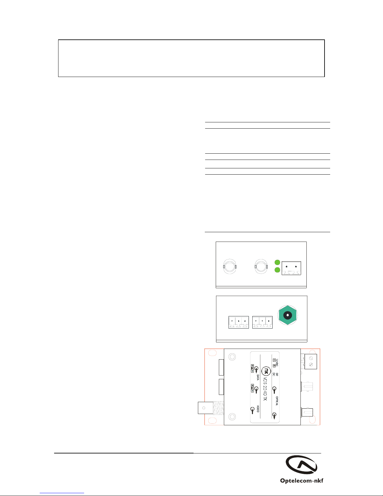
The locations of all optical connections are listed in the
Indications and Connectors section of this manual.
Optical outputs and wavelengths are listed in the Technical
Specifications section of this manual.
EMC
The equipment has been tested and found to meet the CE-
regulations relating to EMC, and complies with the limits
for a Class B device, pursuant to Part 15 of the FCC rules.
These limits are designed to provide reasonable protection
against interference to radio communications in any
installation. The equipment generates, uses and can radiate
radio frequency energy; improper use or special
circumstances may cause interference to other equipment or a
performance decrease due to interference radiated by other
equipment. In such cases, the user will have to take
appropriate measures to reduce such interactions between this
and other equipment.
Any interruption of the shielding inside or outside the
equipment could cause the equipment to be more prone to fail
EMC requirements.
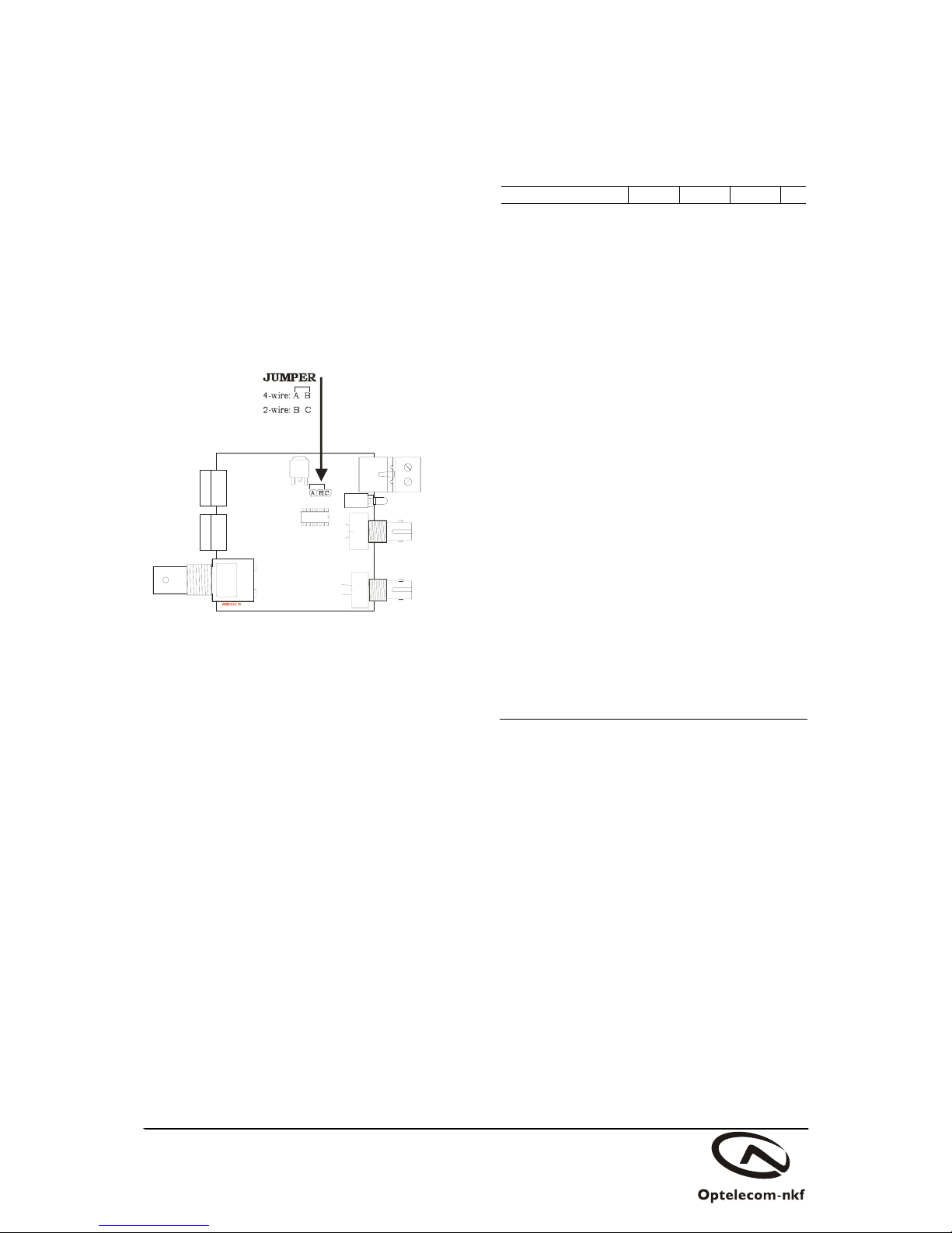
Non-video signal lines must use appropriate shielded CAT5
cabling (S-FTP), or at least an equivalent.
If system components, such as cabling (e.g. coaxial cable,
data/audio/cc wiring) and/or the units, are used outdoors,
ensure that all electrically connected components are
carefully earthed and protected against surges (high voltage
transients caused by switching or lightning).
ESD
Electrostatic discharge (ESD) can damage or destroy
electronic components. Proper precautions should be
taken against ESD when opening the equipment.
*) SELV: conforming to IEC 60950-1, <60VDC output, output
voltage galvanically isolated from mains. All power supplies or
power supply cabinets available from Optelecom-NKF comply
with these SELV requirements.
7. Product disposal
Recycling
The unit contains valuable materials which qualify for
recycling. In the interest of protecting the
natural environment, properly recycling the
unit at the end of its service life is imperative.
Hazard Level 1M
©Optelecom-NKF 2008
Version 001205-4a
VDS TX (MW03SP3)

This manual suits for next models

2

Other Optelecom-nkf Transmitter manuals

Optelecom-nkf 9000 Series User manual

Optelecom-nkf

Optelecom-nkf 9000 Series User manual

Optelecom-nkf 9172DT User manual

Optelecom-nkf

Optelecom-nkf 9172DT User manual

Optelecom-nkf 9131DT User manual

Optelecom-nkf

Optelecom-nkf 9131DT User manual

Popular Transmitter manuals by other brands

RKI Instruments 65-2336RK Operator's manual

RKI Instruments

RKI Instruments 65-2336RK Operator's manual

rojaflex RHS1-W Original assembly and operating instructions

rojaflex

rojaflex RHS1-W Original assembly and operating instructions

GHM-Martens UT125 Series operating manual

GHM-Martens

GHM-Martens UT125 Series operating manual

Tele Radio T26 Series installation instructions

Tele Radio

Tele Radio T26 Series installation instructions

CYP CH-1529TXV Operation manual

CYP

CYP CH-1529TXV Operation manual

Multi-code 3089 installation instructions

Multi-code

Multi-code 3089 installation instructions

AKG FLEXX GUITARBUG GB 40 User instructions

AKG

AKG FLEXX GUITARBUG GB 40 User instructions

Nautel VX150 Operation & maintenance manual

Nautel

Nautel VX150 Operation & maintenance manual

XtremeMac AirPlay IA-AIR-00 manual

XtremeMac

XtremeMac AirPlay IA-AIR-00 manual

Critical Environment Technologies AST-IS5 installation manual

Critical Environment Technologies

Critical Environment Technologies AST-IS5 installation manual

Velleman vm118 user manual

Velleman

Velleman vm118 user manual

Marksman M3 installation manual

Marksman

Marksman M3 installation manual

JUMO TRANS T06 Junior operating manual

JUMO

JUMO TRANS T06 Junior operating manual

DELTA DORE TYXIA 2330 installation guide

DELTA DORE

DELTA DORE TYXIA 2330 installation guide

M-system M5XPA instruction manual

M-system

M-system M5XPA instruction manual

ASTEL TT 404 operating instructions

ASTEL

ASTEL TT 404 operating instructions

MG W5TS instruction manual

MG

MG W5TS instruction manual

Hallicrafters HT-44 Operation and maintenance manual

Hallicrafters

Hallicrafters HT-44 Operation and maintenance manual

manuals.online logo
manuals.online logoBrands
  • About & Mission
  • Contact us
  • Privacy Policy
  • Terms and Conditions

Copyright 2025 Manuals.Online. All Rights Reserved.