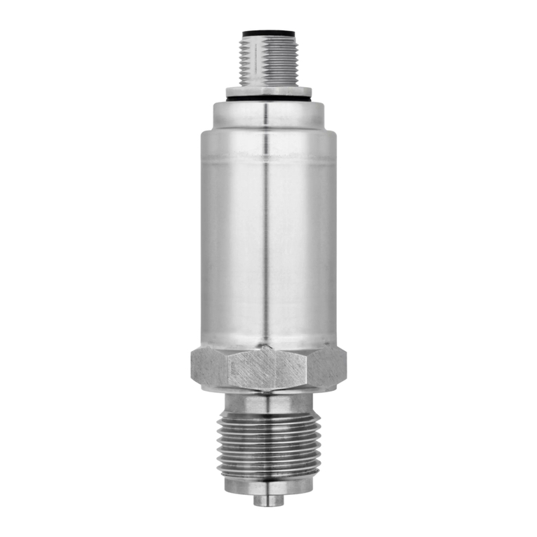
JUMO TAROS S46 H User manual

40207100T90Z001K000
V2.01/EN/00705001/2021-10-14
JUMO TAROS S46 H
Pressure Transmitter
Operating Manual


Contents
Contents
1 Safety information. . . . . . . . . . . . . . . . . . . . . . . . . . . . . . . . . . . . . . . . . . . . 4
2 Introduction . . . . . . . . . . . . . . . . . . . . . . . . . . . . . . . . . . . . . . . . . . . . . . . . . 6
2.1 Intended use . . . . . . . . . . . . . . . . . . . . . . . . . . . . . . . . . . . . . . . . . . . . . . . . . . . . . . . . . . . . .6
2.2 Block diagram . . . . . . . . . . . . . . . . . . . . . . . . . . . . . . . . . . . . . . . . . . . . . . . . . . . . . . . . . . . .6
3 Identifying the device version . . . . . . . . . . . . . . . . . . . . . . . . . . . . . . . . . . 7
3.1 Nameplate. . . . . . . . . . . . . . . . . . . . . . . . . . . . . . . . . . . . . . . . . . . . . . . . . . . . . . . . . . . . . . .7
3.2 Order details . . . . . . . . . . . . . . . . . . . . . . . . . . . . . . . . . . . . . . . . . . . . . . . . . . . . . . . . . . . . .8
3.3 Accessories. . . . . . . . . . . . . . . . . . . . . . . . . . . . . . . . . . . . . . . . . . . . . . . . . . . . . . . . . . . . . .10
4 Mounting . . . . . . . . . . . . . . . . . . . . . . . . . . . . . . . . . . . . . . . . . . . . . . . . . . . 11
4.1 General information . . . . . . . . . . . . . . . . . . . . . . . . . . . . . . . . . . . . . . . . . . . . . . . . . . . . . . .11
4.2 Dimensions . . . . . . . . . . . . . . . . . . . . . . . . . . . . . . . . . . . . . . . . . . . . . . . . . . . . . . . . . . . . . .12
4.2.1 Transmitter with electrical connections . . . . . . . . . . . . . . . . . . . . . . . . . . . . . . . . . . . . . . . . .12
4.2.2 Process connections. . . . . . . . . . . . . . . . . . . . . . . . . . . . . . . . . . . . . . . . . . . . . . . . . . . . . . .13
4.3 Important information for usage according to EHEDG . . . . . . . . . . . . . . . . . . . . . . . . . . . . .14
5 Electrical connection . . . . . . . . . . . . . . . . . . . . . . . . . . . . . . . . . . . . . . . . . 15
5.1 Installation notes . . . . . . . . . . . . . . . . . . . . . . . . . . . . . . . . . . . . . . . . . . . . . . . . . . . . . . . . . .15
5.2 Connection diagram . . . . . . . . . . . . . . . . . . . . . . . . . . . . . . . . . . . . . . . . . . . . . . . . . . . . . . .15
6 Operation . . . . . . . . . . . . . . . . . . . . . . . . . . . . . . . . . . . . . . . . . . . . . . . . . . . 16
6.1 Zero point adjustment . . . . . . . . . . . . . . . . . . . . . . . . . . . . . . . . . . . . . . . . . . . . . . . . . . . . . .16
7 Maintenance, cleaning and returns . . . . . . . . . . . . . . . . . . . . . . . . . . . . . . 17
7.1 Maintenance . . . . . . . . . . . . . . . . . . . . . . . . . . . . . . . . . . . . . . . . . . . . . . . . . . . . . . . . . . . . .17
7.2 Manual cleaning for maintenance or storage . . . . . . . . . . . . . . . . . . . . . . . . . . . . . . . . . . . .17
7.3 Returns . . . . . . . . . . . . . . . . . . . . . . . . . . . . . . . . . . . . . . . . . . . . . . . . . . . . . . . . . . . . . . . . .17
8 Technical data . . . . . . . . . . . . . . . . . . . . . . . . . . . . . . . . . . . . . . . . . . . . . . . 18
8.1 Mechanical features . . . . . . . . . . . . . . . . . . . . . . . . . . . . . . . . . . . . . . . . . . . . . . . . . . . . . . .18
8.2 Measuring range and accuracy. . . . . . . . . . . . . . . . . . . . . . . . . . . . . . . . . . . . . . . . . . . . . . .18
8.3 Electrical data . . . . . . . . . . . . . . . . . . . . . . . . . . . . . . . . . . . . . . . . . . . . . . . . . . . . . . . . . . . .20
8.4 Environmental influences . . . . . . . . . . . . . . . . . . . . . . . . . . . . . . . . . . . . . . . . . . . . . . . . . . .21
8.5 Approvals and approval marks . . . . . . . . . . . . . . . . . . . . . . . . . . . . . . . . . . . . . . . . . . . . . . .22
9 China RoHS . . . . . . . . . . . . . . . . . . . . . . . . . . . . . . . . . . . . . . . . . . . . . . . . . 23

4
1 Safety information
General
This manual contains information that must be observed in the interest of your own safety and to avoid
material damage. This information is supported by symbols which are used in this manual as indicated.
Please read this manual before starting up the device. Store this manual in a place that is accessible to
all users at all times.
If difficulties occur during startup, please do not intervene in any way that could jeopardize your warranty
rights!
Warning symbols
DANGER!
This symbol indicates that personal injury from electrocution may occur if the appropriate precaution-
ary measures are not taken.
WARNING!
This symbol in connection with the signal word indicates that personal injury may occur if the respective
precautionary measures are not carried out.
CAUTION!
This symbol in connection with the signal word indicates that material damage or data loss will occur
if the respective precautionary measures are not taken.
CAUTION!
This symbol indicates that components could be destroyed by electrostatic discharge (ESD = Electro
Static Discharge) if the respective cautionary measures are not taken.
Only use the ESD packages intended for this purpose to return device inserts, assembly groups, or as-
sembly components.
Note symbols
NOTE!
This symbol refers to important information about the product, its handling, or additional benefits.
READ THE DOCUMENTATION!
This symbol, which is attached to the device, indicates that the associated documentation for the de-
vice must be observed. This is necessary to identify the nature of the potential hazard, and to take
measures to prevent it.
REFERENCE!
This symbol refers to additional information in other sections, chapters, or other manuals.
FURTHER INFORMATION!
This symbol is used in tables and indicates that further information is provided after the table.
&

5
1 Safety information
DISPOSAL!
At the end of its service life, the device and any batteries present do not belong in the trash! Please en-
sure that they are disposed of properly and in an environmentally friendly manner.

6
2 Introduction
2Introduction
2.1 Intended use
The pressure transmitter is used to acquire relative and absolute pressures in liquid and gaseous media.
The JUMO TAROS S46 H with analog output signal has been developed specifically for hygienic appli-
cations. The pressure transmitter has a pressure measuring cell with a piezoresistive silicon sensor. The
pressure is converted into an electrical current or voltage signal and output via various electrical connec-
tions.
A built-in magnetoresistive switch (MRS) enables the user to adjust the zero point of the device exter-
nally using a magnet.
The pressure transmitter is EAC-compliant and UL-approved1. It is certified according to EHEDG in the
versions with the process connections clamp, VARIVENT®, and JUMO PEKA.
The protection offered by the device may be impaired if the device is used in a way that does not
comply with the manufacturer’s intended use.
2.2 Block diagram
1The approval stipulates use of the transmitter indoors only. All surfaces are made from stainless steel
in the versions with electrical connection 36 (round plug M12 × 1) and electrical connection 75 (ter-
minal head). These versions of the transmitter are also suitable for outdoor use.
Voltage supply
DC 8 to 30 V with two-wire
output (4 to 20 mA)
DC 11,5 bis 30 V with three-wire
output (0 to 10 V)
DC 10 to 30 V with three-wire
output (1 to 5 V and 1 to 6 V)
Pressure transmitter
Operation
Zero point correction with magnet
Measurand
Relative pressure
Absolute pressure
Output signal
Two-wire: 4 to 20 mA
Three-wire: DC 0 to 10 V or
DC 1 to 5 V or
DC 1 to 6 V

7
3 Identifying the device version
3.1 Nameplate
Position
The nameplate is laser-etched on the device surface.
Table of contents
The nameplate shows important information. This includes:
Device type (Typ)
Compare the specifications on the nameplate with your order documents. The supplied device version
can be identified using the order code (chapter 3.2 "Order details", Page 8).
Part no. (TN)
The part no. uniquely identifies an article in the catalog. It is important for communication between the
customer and the sales department.
Fabrication number (F-Nr.)
Among other things, the fabrication number indicates the production date (year/week) and the hard-
ware version number.
The production date is represented by digits 12 to 15 (from the left).
Example: F-No = 0123456701020240123.
The device in this example was produced in the year 2020, in the 24th week.
Description Designation on the nameplate Example
Device type Typ 402071/000
Part no. TN 00123456
Measuring range 0 to 0.1 bar relative pressure
Voltage supply DC 8 to 30 V/25 mA
Output signal 4 to 20 mA
Fabrication number F-Nr. 0123456701020240123

3 Identifying the device version
8
3.2 Order details
(1) Basic type
402071 JUMO TAROS S46 H – pressure transmitter
(2) Basic type extension
000 None
045 Autoclave-compatible versiona, b
051 Relative-pressure version without zero point adjustment
999 Special version
(3) Input
478 -1 to 0 bar relative pressure
479 -1 to +0.6 bar relative pressure
449 -1 to +1 bar relative pressure
480 -1 to +1.5 bar relative pressure
481 -1 to +3 bar relative pressure
482 -1 to +5 bar relative pressure
483 -1 to +9 bar relative pressure
484 -1 to +15 bar relative pressure
485 -1 to +24 bar relative pressure
428 -0.4 to +0.4 bar relative pressure
427 -0.1 to +0.1 bar relative pressure
425 0 to 0.1 bar relative pressure
426 0 to 0.16 bar relative pressure
451 0 to 0.25 bar relative pressure
452 0 to 0.4 bar relative pressure
453 0 to 0.6 bar relative pressure
454 0 to 1 bar relative pressure
455 0 to 1.6 bar relative pressure
456 0 to 2.5 bar relative pressure
457 0 to 4 bar relative pressure
458 0 to 6 bar relative pressure
459 0 to 10 bar relative pressure
460 0 bar to 16 bar relative pressure
461 0 bar to 25 bar relative pressure
462 0 bar to 40 bar relative pressure
463 0 bar to 60 bar relative pressure
464 0 bar to 100 bar relative pressure
487 0 to 0.6 bar absolute pressure
488 0 to 1 bar absolute pressure
489 0 to 1.6 bar absolute pressure
490 0 to 2.5 bar absolute pressure
491 0 to 4 bar absolute pressure
500 0 to 5 bar absolute pressure
492 0 to 6 bar absolute pressure
493 0 to 10 bar absolute pressure
494 0 to 16 bar absolute pressure

9
3 Identifying the device version
495 0 to 25 bar absolute pressure
505 0 to 40 bar absolute pressure
998 Special measuring range for absolute pressure
999 Special measuring range for relative pressure
(4) Output
405 4 to 20 mA, 2-wire
415 DC 0 to 10 V, three-wire
418 DC 1 to 5 V, three-wire
420 DC 1 to 6 V, three-wire
(5) Process connection
604 Taper socket with union nut DN 25, DIN 11851 (dairy pipe fitting)c
607 Taper socket with union nut DN 50, DIN 11851 (dairy pipe fitting)d
613 Clamping socket (clamp) DN 25, 32, 40, DIN 32676e
616 Clamping socket (clamp) DN 50, DIN 32676, 2" ISO 2852e
652 Tank connection with grooved union nut DN 25c
653 Tank connection with grooved union nut DN 40c
685 VARIVENT® connection DN 32/25
686 VARIVENT® connection DN 50/40
997 JUMO PEKA hygienic process connection
(6) Process connection material
53 Stainless steel 1.4404/1.4435
(7) Electrical connection
12 Attached cable, shielded, length of 2 m
36 Round plug M12 × 1
61 Line socket DIN EN 175301-803, form A
75 Terminal head
(8) Measuring system, filling medium
01 Silicone oil
(9) Extra codes
000 None
061 With UL approvalf
374 Inspection certificate 3.1 EN 10204 – material
452 Parts wetted by medium electrolytically polished
462 Inverted output signal
624 Oil and grease free
870 Inspection certificate 3.1 EN 10204 – surface
871 Inspection certificate 3.1 EN 10204 – accuracy
872 Declaration of compliance with the order 2.1 EN 10204 – material
873 Declaration of compliance with the order 2.1 EN 10204 – surface
874 Declaration of compliance with the order 2.1 EN 10204 – accuracy
875 Declaration of compliance with the order 2.1 EN 10204 – data sheet
aOnly with round plug M12 × 1 (electrical connection 36).
bIf the devices work with relative pressure, the relative pressure is compensated using round plug M12 × 1. To en-
sure reliable pressure compensation, use a corresponding mating connector with pressure equalization hose in the
cable (part no. 00512341). Alternatively, a pressure compensation adapter (part no. 00739821) can be used.
cOnly possible with measuring ranges up to 40 bar.
dOnly possible with measuring ranges up to 25 bar.

3 Identifying the device version
10
3.3 Accessories
NOTE!
The following accessories are not UL-approved.
NOTE!
When using a transmitter with UL approval, the user must make sure that the accessory he uses is also
approved for a UL application (e.g. cable with UL approval AVLV2/8 and/or cable with UL approval
CYJV/7 or CYJV/8 or PVVA/7 or PVVA2/8, in each case approved for ambient temperatures > 90 °C).
eThe maximum measuring range that can be used is based on the clamp's pressure stage.
fNot possible with electrical connection 12 (attached cable).
(1) (2) (3) (4) (5) (6) (7) (8) (9)
Order code /------/
Order example 402071 / 999 - 453 - 405 - 613 - 53 - 36 - 01 / 374,870
Item Part no.
Cable socket, 4-pole, M12 × 1, straight, with 5 m PVC cable, with PA pressure equalization
hose
00512341
Line socket, 4-pole, M12 × 1, straight, with 2-m PVC cable, without pressure compensation 00404585
Line socket, 4-pole, M12 × 1, angled, with 2-m PVC cable, without pressure compensation 00409334
Magnetic pin for simple adjustment of zero point 00736330
End cap M12 × 1 (for autoclave-compatible version) 00736095
Pressure compensation adapter M12 × 1 00739821

11
4 Mounting
4 Moun ti ng
4.1 General information
NOTE!
Check that the device is compatible with the measurement medium chapter 8.4 "Environmental in-
fluences", Page 21.
Mounting site
• Ensure that the device is fastened safely and with low vibrations
• Avoid direct sunlight
• Please note the admissible ambient temperatures at the installation position
chapter 8.4 "Environmental influences", Page 21
Installation position
The device can be installed in any position.
We recommend the "upright" installation position, as shown below:

4 Mounting
12
4.2 Dimensions
4.2.1 Transmitter with electrical connections
12 36
Attached cable, length of 2 m (standard) Round plug M12 × 1
61 75
Line socket DIN EN 175301-803, form A Terminal head
Cable fitting M16, seal area 5 to 11 mm
PA = process connection
L
12.5
M12
PA
L(mm)
604, 607, 613, 616,
685, 686, 997
73
652, 653
48
L
M
PA
L(mm)
M(mm)
604, 607,
613, 616,
685, 686,
997
96
85
652, 653
71
60

13
4 Mounting
4.2.2 Process connections
604 607
Taper socket with union nut DN 25 Taper socket with union nut DN 50
613 616
Clamping socket (clamp) DN 25, 32, 40 Clamping socket (clamp) DN 50
652 653
Tank connection with grooved union nut DN 25 (includ-
ing welding socket)
Tank connection with grooved union nut DN 40 (includ-
ing welding socket)
685 686
VARIVENT® connection DN 32/25 VARIVENT® connection DN 50/40
Sealing ring, FPM Sealing ring, EPDMa
aEHEDG conformity according to "EHEDG Position Paper" is only ensured with EPDM.
24
16
Ø 63
25
17
Ø 92
15
Ø 50.5
15
Ø 64

4 Mounting
14
NOTE!
Detailed specifications on the JUMO PEKA process connection system can be found in data sheet
409711.
Other process connections upon request!
4.3 Important information for usage according to EHEDG
The following process connections are suitable for usage according to EHEDG:
• 613 and 616 (Clamp DN 25/32/40/50 with Tri-Clamp seals Combifit International B.V.)
• 685 and 686 (VARIVENT® connections DN 32/25 and DN 50/40 with EPDM O-ring)
• 997 (JUMO PEKA with FKM O-ring)
The pressure transmitter is suitable for CIP (Cleaning in Place) when installed accordingly. For details of
the temperature resistance and material resistance, see chapter 8.4 "Environmental influences",
Page 21.
Observe the following points to ensure EHEDG compliant integration in the respective plants:
• Where possible, provide a cavity-free installation.
• Install the connecting sockets so that they are self-draining.
• Use only EHEDG approved process connections according to the current EHEDG position paper.
• When used on tanks, the installation must be front-flush. Cleaning through direct spraying must be
ensured. Cavities must be detectable.
• Install the leakage opening so that it is clearly visible. Install vertical lines facing downwards.
The following drawing shows an example installation. To avoid cavities, L must be < D.
997
JUMO PEKA
32.5
20.5
Ø 36
(1) Leakage opening
(2) Rear seal
(3) Front-flush seal

15
5 Electrical connection
5.1 Installation notes
NOTE!
The electrical connection must only be performed by qualified personnel.
5.2 Connection diagram
The electromagnetic compatibility meets standard DIN EN 61326.
Do not connect any additional loads to the voltage supply of the device.
The device is not suitable for installation in potentially explosive areas.
Connection Terminal assignmenta
12 36 61 75
Attached cable Round plug
M12 × 1
Cable socket Terminal head
4 to 20 mA, 2-wire (output 405)
Voltage supply DC 8 to 30 V UB/S+White111
0V/S-Black322
DC 0 to 10 V, 3-wire (output 415)
Voltage supply DC 11.5 V to 30 V UBWhite111
0V/S-Black222
S+ Yellow 3 3 3
DC 1 to 5 V, three-wire (output 418)
DC 1 to 6 V, three-wire (output 420)
Voltage supply DC 10 to 30 V UBWhite111
0V/S-Black222
S+ Yellow 3 3 3
Functional bonding conductor FBb
(all output variants)
Shield/green 4 4
aFigure: Connection to the pressure transmitter
bAs a basic principle, the device is grounded via the process connection. Alternatively, the device can also be
grounded via the electrical connection on all variants. However, grounding via both the process connection and the
electrical connection is not admissible.
1
4
2
3
1
2
3
1234
Admissible effect on the "attached
cable" variant
Smallest bending radius (fixed) 40 mm
Max. tensile force on the cable 20 N

16
6 Operation
6Operation
6.1 Zero point adjustment
General Information
In the case of device versions designed for relative pressure, there is the option of a simple pressure/
zero point adjustment (offset) using a magnet (remanence BR≥ 1 T, e.g. NdFeB dia. 4 × 10 mm). This
actuates a magnetoresistive switch inside the device when approaching it. A suitable magnet is available
from JUMO as an accessory (part no. 00736330).
This provides a quick and simple way to correct zero point offsets caused by the installation or zero point
offsets that have arisen following autoclaving, for example.
Requirements
The following conditions must be met in order to carry out a successful zero point adjustment:
• The adjustment must take place within a timeframe of a maximum of 2 seconds once the device
is switched on.
• The pressure at the device at the point of the zero point adjustment must not deviate more than
±10 % from the positive pressure measuring range of the device1.
Procedure
NOTE!
If the magnetic field is not applied within the timeframe of approx. 2 seconds after the device is switched
on, it will not affect the zero point of the device.
A further zero point adjustment can only take place once the device has been switched off and switched
back on again.
1Example 1: Measuring range 0 to 1 bar rel.; deviation from ambient pressure max. ±0.1 bar.
Example 2: Measuring range -1 to +0.6 bar rel.; deviation from ambient pressure max. ±0.1 bar.
Example 3: Measuring range -1 to 5 bar rel.; deviation from ambient pressure max. ±0.5 bar.
1. Hold the magnet at the position of the QR
code (1) on the nameplate of the device.
2. Switch on the voltage supply for the de-
vice.
The device recognizes the magnet (within
the first 2 seconds) and automatically re-
adjusts the zero point. As a result, the
switch-on time is slightly delayed
3. Remove the magnet from the housing and
keep it for further use.
The zero point adjustment is complete. The
new zero point is permanently saved. Howev-
er, you can carry out a further zero point ad-
justment at any time.

17
7 Maintenance, cleaning and returns
7 M aint enan ce, cle ani ng and ret ur ns
7.1 Maintenance
The pressure transmitter is maintenance-free.
In the event of a malfunction, please return the device to the manufacturer together with accurate fault
information.
7.2 Manual cleaning for maintenance or storage
The pressure transmitter – especially the parts in contact with the product – must not be damaged. Any
damage to the stainless steel membrane must be avoided. The cleaning agent must not attack the sur-
face and seals.
Note the protection type of the device.
WARNING!
Risk of burning due to hot surfaces
In the CIP/SIP cleaning process, the pressure transmitter’s surfaces are subjected to hot temperatures
of up to 140 °C. Contact with these surfaces could result in burns to the skin.
When servicing the transmitter, check its surface temperature and, if necessary, wait until it has
cooled.
7.3 Returns
NOTE!
In case of abnormalities, please send the device to the manufacturer together with a completed cover
note for product returns. You can download a blank copy of this cover note online at:
http://produktruecksendung.jumo.info.

18
8 Technical data
8 Tech ni cal da ta
8.1 Mechanical features
8.2 Measuring range and accuracy
Materials of parts coming into contact
with the pressurized medium
Membrane Stainless steel 1.4435 (316 L)
O-ring/sealing ring FPM, others available as an optional extra (e.g. EPDM, VMQ)
Process connection Stainless steel 1.4404 (316 L)
Welding ring Stainless steel 1.4404 (316 L)
Materials of other parts
Housing Stainless steel 1.4301 (304)
Cover cap M12 × 1aStainless steel 1.4301 (304)
Electrical connection
Attached cable Cable fitting made from stainless steel 1.4301 (304); PUR cable with and
without pressure compensation
Round plug M12 × 1 Threaded bushing made from stainless steel 1.4301 (304)
Cable socket Holding ring/connector fastener made from high-quality plastic, comparable
with PBT GF30 V0
Terminal head Stainless steel 1.4301 (304); cable fitting: stainless steel
Rated position Upright, with downward process connection
Operating position Any, but there may be a zero offset relative to the rated position
aIncluded on autoclave-compatible variant.
Measuring range LinearityaAccuracy at Long-
term
stabilityb
Overload
capabili-
tyc
Burst
pressure
20 °Cd-20 to
+80 °Ce
-20 to
+100 °C
% MSPf% MSP % MSP % MSP % MSP
per year
bar bar
-1 to 0 bar relative pressure 0.15 0.3 1 1.2 ≤ 0.15 10 20
-1 to +0.6 bar relative pressure 0.15 0.3 1 1.2 ≤ 0.15 10 20
-1 bar to +1 bar relative pressure 0.15 0.3 1 1.2 ≤ 0.15 10 20
-1 to +1.5 bar relative pressure 0.15 0.3 1 1.2 ≤ 0.15 20 40
-1 to +3 bar relative pressure 0.1 0.25 0.75 0.8 ≤ 0.1 25 50
-1 to +5 bar relative pressure 0.1 0.25 0.75 0.8 ≤ 0.1 50 60
-1 to +9 bar relative pressure 0.1 0.25 0.75 0.8 ≤ 0.1 50 60
-1 to +15 bar relative pressure 0.1 0.25 0.75 0.8 ≤ 0.1 120 200
-1 to +24 bar relative pressure 0.1 0.25 0.75 0.8 ≤ 0.1 120 200
-0.4 to +0.4 bar relative pressure 0.15 0.4 1 1.2 ≤ 0.2 10 20
-0.1 to +0.1 bar relative pressure 0.2 0.5 1 1.2 ≤ 0.2 6 10
0 to 0.1 bar relative pressure 0.25 0.75 1.2 --- ≤ 0.2 1.5 3
0 to 0.16 bar relative pressure 0.25 0.75 1.2 1.5 ≤ 0.2 6 10
0 to 0.25 bar relative pressure 0.25 0.5 1 1.2 ≤ 0.2 6 10
0 to 0.4 bar relative pressure 0.15 0.4 1 1.2 ≤ 0.15 10 20
0 to 0.6 bar relative pressure 0.15 0.4 1 1.2 ≤ 0.15 10 20
0 to 1 bar relative pressure 0.15 0.3 1 1.2 ≤ 0.15 10 20
0 to 1.6 bar relative pressure 0.15 0.3 1 1.2 ≤ 0.15 20 40

19
8 Technical data
0 to 2.5 bar relative pressure 0.15 0.3 1 1.2 ≤ 0.1 20 40
0 to 4 bar relative pressure 0.1 0.25 0.75 0.8 ≤ 0.1 25 50
0 to 6 bar relative pressure 0.1 0.25 0.75 0.8 ≤ 0.1 50 60
0 to 10 bar relative pressure 0.1 0.25 0.75 0.8 ≤ 0.1 50 60
0 bar to 16 bar relative pressure 0.1 0.25 0.75 0.8 ≤ 0.1 120 200
0 bar to 25 bar relative pressure 0.1 0.25 0.75 0.8 ≤ 0.1 120 200
0 bar to 40 bar relative pressure 0.1 0.25 0.75 0.8 ≤ 0.1 300 400
0 bar to 60 bar relative pressure 0.1 0.25 0.75 0.8 ≤ 0.1 300 400
0 bar to 100 bar relative pressure 0.1 0.25 0.75 0.8 ≤ 0.1 300 400
0 to 0.6 bar absolute pressure 0.15 0.4 1 1.2 ≤ 0.15 10 20
0 to 1 bar absolute pressure 0.15 0.3 1 1.2 ≤ 0.15 10 20
0 to 1.6 bar absolute pressure 0.15 0.3 1 1.2 ≤ 0.15 20 40
0 to 2.5 bar absolute pressure 0.15 0.3 1 1.2 ≤ 0.1 20 40
0 to 4 bar absolute pressure 0.1 0.25 0.75 0.8 ≤ 0.1 25 50
0 to 5 bar absolute pressure 0.1 0.25 0.75 0.8 ≤ 0.1 25 50
0 to 6 bar absolute pressure 0.1 0.25 0.75 0.8 ≤ 0.1 50 60
0 to 10 bar absolute pressure 0.1 0.25 0.75 0.8 ≤ 0.1 50 60
0 to 16 bar absolute pressure 0.1 0.25 0.75 0.8 ≤ 0.1 120 200
0 to 25 bar absolute pressure 0.1 0.25 0.75 0.8 ≤ 0.1 120 200
0 to 40 bar absolute pressure 0.1 0.25 0.75 0.8 ≤ 0.1 200 300
aLinearity according to limit point setting
bReference conditions EN 61298-1
cAll measuring ranges are vacuum proof.
dIncludes: linearity, hysteresis, repeatability, deviation of measuring range start value (offset) and measuring range
end value
eIncludes: linearity, hysteresis, repeatability, deviation of measuring range start value (offset) and measuring range
end value, thermal effect on measuring range start (offset) and measuring span
fMSP = measuring span
Measuring range LinearityaAccuracy at Long-
term
stabilityb
Overload
capabili-
tyc
Burst
pressure
20 °Cd-20 to
+80 °Ce
-20 to
+100 °C
% MSPf% MSP % MSP % MSP % MSP
per year
bar bar

8 Technical data
20
8.3 Electrical data
Voltage supplya
2-wire circuitb
4 to 20 mA DC 8 to 30 V, nominal voltage DC 24 V
3-wirec
DC 0 to 10 V DC 11.5 V to 30 V, nominal voltage DC 24 V
DC 1 to 5 V DC 10 V to 30 V, nominal voltage DC 24 V
DC 1 to 6 V DC 10 V to 30 V, nominal voltage DC 24 V
aThe auxiliary energy of the pressure transmitter must meet SELV requirements. Furthermore, the device must be
equipped with an electrical circuit that meets the requirements of EN 61010-1 with regard to "Limited-energy cir-
cuits".
bMaximum current consumption ≤ 25 mA.
cMaximum current consumption ≤ 5 mA.
Burden/loada
2-wire circuit
4to20mA R
L≤ (UB -8 V) ÷ 0.02 A (Ω)
3-wire
DC 0 to 10 V RL≥ 10 kΩ
DC 1 to 5 V RL≥ 10 kΩ
DC 1 to 6 V RL≥ 10 kΩ
aMaximum effect < 0.5 %.
Behavior if measured value is out of
range
Error signal in the case of NAMUR exceedance, linear
Two-wire
4 to 20 mA ≤ 3.6 mA and ≥ 21.5 mA 3.8 to 20.5 mA
Three-wire
DC0to10V 10.7V 0to10.5V
DC 1 to 5 V 5.7 V 0.8 to 5.5 V
DC 1 to 6 V 6.7 V 0.8 to 6.5 V
Behavior after power on Ready for operation after < 120 ms
Voltage supply influence ≤ 0.02 %/V
Reverse voltage protection UB to 0 V (all output variants)
Short-circuit resistance S+ to 0 V (only voltage variants)
Overvoltage protection The operating voltage must be restricted to max. 33 V
Step response of 90 % (according
to DIN 16068 Point 3.3.8)
<5ms
Insulation resistance > 100 MΩ at DC 500 V
Insulation voltage AC 500 V
Table of contents
Other JUMO Transmitter manuals

JUMO
JUMO dTRANS p02 User manual

JUMO
JUMO dTRANS T06 Ex User manual

JUMO
JUMO dTRANS T03 J User manual

JUMO
JUMO dTRANS O2 01 User manual

JUMO
JUMO ecoTRANS Lf 01 User manual

JUMO
JUMO dTRANS T02 Ex User manual

JUMO
JUMO ecoTRANS Lf 03 User manual

JUMO
JUMO dTRANS p02 User manual

JUMO
JUMO dTRANS T07 Reference guide

JUMO
JUMO AQUIS 500 CR User manual

JUMO
JUMO DELOS SI User manual

JUMO
JUMO MIDAS S22 Ex User manual

JUMO
JUMO 40.2005 User manual

JUMO
JUMO B 90.7027.1 User manual

JUMO
JUMO CTI-500 User manual

JUMO
JUMO TAROS S47 P User manual

JUMO
JUMO dTRANS p02 DELTA User manual

JUMO
JUMO CTI-750 User manual
JUMO
JUMO dTRANS T07 User manual

JUMO
JUMO SIRAS P21 DP User manual