Optex TSC-10-D User manual

Thank you very much for purchasing Turbidity Checker TSC-10-D.
All of this instruction manual must be read before operation of this
Turbidity Checker for safe and proper operation.
This instruction manual should be kept for future reference such as
maintenance.
Turbidity Checker
TSC-10-D
Instruction
Manual
WATER it
The instruction manual is also available on the following website.
https://navi.optex.net/manual/05337/?lang=en

2
The Contents of Packaging
Sensor: 1 Cable protective cover: 1
Cable tying band: 5 Cleaning brush: 1
Detection window
cleaning paper: 1
Instruction manual
(this document)
If there are any missing or faulty items, please contact our sales
representative.
Reference
Can be connected to SC-U1.

3
Table of Contents
1 For Safe Use........................................................................... 5
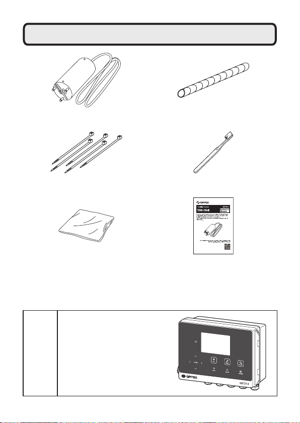
2 Component Name.................................................................. 7
3 Measuring Principle .............................................................. 8
4 Installation.............................................................................. 9
Sensor installation................................................................. 9
Extension of sensor cable................................................... 12
5 Wiring ................................................................................... 13
6 Sensor Setting ..................................................................... 14
Display item (unit selection)................................................ 14
Response time.................................................................... 15
7 4-20 mA Setting ................................................................... 16
Output item selection .......................................................... 16
Upper/lower limit of signal output range.............................. 17
8 Relay Setting........................................................................ 18
Alarm output setting............................................................ 18
Maintenance output setting................................................. 19
Self Checking output setting ............................................... 19
9 Calibration............................................................................ 20
Zero calibration ................................................................... 20
10 Adjustment........................................................................... 23
Offset adjustment................................................................ 23
Span adjustment................................................................. 25
2-point adjustment .............................................................. 26
Adjustment initialization ...................................................... 29

4
11 Maintenance Setting............................................................ 30
Measurement value hold..................................................... 30
Hold timer............................................................................ 30
Maintenance timer .............................................................. 31
12 Cleaning ............................................................................... 32
Manual cleaning.................................................................. 32
Cleaning interval ................................................................. 33
13 Troubleshooting .................................................................. 34
Error code list...................................................................... 34
14 Maintenance......................................................................... 36
Maintenance (monthly) ....................................................... 36
Periodic inspection (every 3 months).................................. 36
Replacement of consumables............................................. 36
Calibration........................................................................... 37
Long-term storage............................................................... 37
Overhaul ............................................................................. 37
15 Specifications ...................................................................... 38
16 External Dimensions........................................................... 39

5
Be sure to read this instruction manual in order to
use this Turbidity Checker properly.
●Please thoroughly read "For Safe Use" before using this Turbidity
Checker properly.
●Because these precautions are related to failure or malfunction, observe
the precautions for use without fail.
Do not use TSC-10-D except for measurement of water
quality.
" " denotes "Prohibited action", and " " denotes "Required action" .
In the unlikely event of
occurrence of abnormalities
such as smoke or abnormal
noise, immediately turn off
the power.
Do not disassemble or
modify the sensor.
Handle with care not to
damage.
Use the sensor with
24 VDC.
24 VDC
1 For Safe Use

6
To clean the sensor, first
wipe away lightly with a clean
soft cloth damped by diluted
mild detergent solution and
then wipe off moisture with
a dry clean soft cloth.
Do not wipe the sensor with
solvent such as Thinner.
It may cause failure.
2UJDQLF
6ROYHQW
7KLQQHU
HWF
Avoid strong physical
shock to the sensor or do
not drop it.
Do not apply oil such as
grease to the sensor.

7
2 Component Name
Sensor cable
Detection windows
Wiper blade
Caution
・Do not carry the sensor with the sensor cable.
・Do not touch the detection window. Clean the detection window
if your hand touches it.

8
3 Measuring Principle
Turbidity Checker TSC-10-D uses a method of 90 degrees scattered light. In
the method, a light source of a sensor illuminates the surfaces of suspend-
ed matter floating in the water, and the light is scattered by these surfaces
is detected by a photo element installed at an angle of 90 degrees from the
light source. The turbidity is determined by the amount of scattered light.
Photo elementLight source (LED)
Caution
Turbidity Checker uses a method of scattered light to
measure amount of reflected light. Therefore, measurement
values may be affected by measurement light reflected from
equipment surfaces or accumulated materials if the sensor is
installed nearby. Install the sensor with a clearance of at least
30 cm from the sensor surface to equipment or other surfaces.
If it is close, the measurement light hits and
the reflected light affects the measurement value.
Allow clearance of
at least 30 cm.
Wall or
other
surface

9
4 Installation
Before installation, turn off the power switch of SC-U1 or
disconnect the power cable from the supply source and wire
the power cable after the installation is complete.
" " denotes "Prohibited action", and " " denotes "Required action" .
When installing the sensor,
make sure that the sensor
is oriented relative to the
water flow as shown in the
illustration. Otherwise,
suspended matter in the
water will adhere to the
detection surface and affect
the measurement value.
Do not install the sensor with
the sensor surface facing
down. Bubbles may
accumulate in the
measurement area, or the
measurement light may be
reflected off the bottom of
the facility or accumulated
objects, making it impossible
to measure correctly.
Water flow
Do not install the sensor
near a wall or other
surface. Measurement light
will strike the surface and
the reflected light will affect
the measurement values.
Install the sensor avoiding
the situation that the
sensor surface receive
strong light such as
sunlight directly.
Wall or
other
surface
Sensor installation

10
With fluctuation of water
level taken into account,
dispose the sensor so as
to be immersed up to of the
order of 30 cm below the
expected lowest water level.
Dispose the sensor in
water without air bubbles.
30 cm min.
(2 meter max.)
Reference
The sensor can be installed in landscape
orientation, and in order to prevent the
sensor from hitting the side wall or
rotating by the water flow, a mounting
attachment (TA-3) for fixing the sensor to
the pipe is available as an option.
For details, contact the dealer or visit our
website:
https://www.optex.co.jp/e/products/
environmental-sensor/
*Pipe: The 25A stainless steel pipe (outer
diameter 34 mm) for piping to be
prepared by the user.
・Read the precautions in the “TA-3 instruction manual” carefully.
・Be sure to install the cable protective cover. Otherwise the cable may be
damaged and flooded during maintenance.

11
Wrap the cable protective cover on the sensor side of the
sensor cable.
Attach the end of the cable protective cover to a pipe with a
cable tying band.
1
2
Cover the cable protective
cover over the end of the
sensor cable.
Be sure to install the cable protective cover.
The cable may be damaged and flooded during
maintenance.
Do not hang the sensor with the sensor cable.
If there are walls, equipment, bottom surfaces, or
accumulations near the facility, the measurement light will
be reflected by them, affecting the measurement value.
Keep the detection surface at least 30 cm away from the
facility wall.

12
Extension of sensor cable
The standard length of the sensor cable is 9 m. To extend the cable, refer to
the following.
To extend the cable, connection using pull box is recommended.
The cable gland fits the cable sheath diameter of 6 to 8 mm.
Max. cable length X
Pull box, etc.
Nominal
sectional area Max. cable length X
0.3 mm220 m
0.5 mm240 m
0.75 mm270 m
1.0 mm2100 m

13
5 Wiring
Before wiring, turn off the power switch of SC-U1 or
disconnect the power cable from the supply source and wire
the power cable after all the other wiring is complete.
Connect the sensor to SC-U1.
・The cable gland fits the cable sheath
diameter of 6 to 8 mm.
・The sensor cable must be shielded
(CVV-S) with a nominal cross-sectional
area of 0.2 to 1.25 mm2.
・Refer to “Extension of sensor cable”
P.12 for extension of the sensor cable.
To extend the sensor cable, connection
using pull box is recommended.
・Wire the terminal block according to the
color of the tip of each wire.
Use this product by connecting to Universal Transmitter SC-U1.
For installation and wiring to SC-U1, refer to the "Universal Transmitter
SC-U1 Installation Manual".
1
Sensor
Sensor
power
supply
Signal
input
(RS485)
(Blue) (Brown)(Black)
(White)
Shielded wire
Power supply +
Power supply -
RS485 A
RS485 B

Sensor Setting
14
6 Sensor Setting
The following settings are available from SC-U1.
To start sensor setting, press .
Set the unit of turbidity to show on the SC-U1 display.
㸯7XUE
5/<
178
Main display
Display item (unit selection)
For operation, refer to the "Universal Transmitter SC-U1 Operation
Manual", "5.1 Sensor Setting" and " ◆Display Item".
Caution
Pressing automatically retains the measurement value.
Measurement item Display item Factory default
setting
Item Unit
Main
display
Turbidity Turb. NTU Turb. NTU
Turb. FNU
Turb. mg/L
Turb. 度
Turb. No unit
Caution
When the display item is changed, the settings of “7 4-20 mA
Setting” P.16 and “8 Relay Setting” P.18 that have set the
display item become OFF.
In addition, the values of “10 Adjustment”, “Offset adjustment”
P.23, “Span adjustment” P.25, and “2-point adjustment”
P.26 are reset to the factory default values.
Set again if necessary.

Sensor Setting
15
The following display resolutions are available.
・0.00 - 19.99: 0.01
・20.0 - 1000.0: 0.1
・NTU: EPA-compliant unit.
・FNU: Unit compliant with ISO7027.
・mg/L: Unit selected for use as a simplified measure found by the cor-
relation between the measurement value (e.g. floating suspended
matter (SS) in the official method) and the value displayed on the
Turbidity Checker.
(Refer to “10 Adjustment” P.23)
・度 : Unit is used only in Japan.
・No unit: Use as required.
Caution
This device creates a calibration curve using formazin standard
solution.
If “ 度” is selected, the calibration curve created using polystyrene
standard solution calculated from formazin standard solution is
shown.
The measurement accuracy will not change even if the unit is
changed.
Response time
Set a signal output response time.
A measurement value is calculated using moving average of the time period
set by the signal output response time.
For example, if the sensor measures values every 5 seconds and the signal
output response time is set to 50 seconds, which is 5 seconds ×10 times,
the moving average of 10 times measurement is calculated and used as the
measurement value.
Setting range Factory default
setting
Response Time 5 to 600 seconds (by 5 seconds) 5 seconds
For operation, refer to the "Universal Transmitter SC-U1 Operation
Manual", "5.1 Sensor Setting" and " ◆Response Time".
The recommended value for this product is 30 seconds or longer.
If the response is too fast with the factory default setting (5 seconds),
change the signal output response time as needed.

4-20 mA Setting
16
Set the 4-20 mA signal output setting from SC-U1.
The factory default setting is OFF for 4-20 mA signal output.
To set 4-20 mA output setting, press .
7 4-20 mA Setting
Select an item to output by 4-20 mA signal.
Output item selection
Output item
[Display]
Turbidity
[Turb.]
For operation, refer to the "Universal Transmitter SC-U1 Operation
Manual", "5.3 4-20 mA Setting" and " ◆Output Item Select".
Caution
Pressing automatically retains the measurement value.
Caution
When “Display item (unit selection)” P.14 is changed, the out-
put item of the channel of 4-20 mA setting that has set the display
item becomes OFF.
Set again if necessary.

4-20 mA Setting
17
For the item by 4-20 mA signal output, set measurement value to output
at lower limit (Lo, 4 mA) and upper limit (Hi, 20 mA).
20 mA
Signal output
4 mA
Measurement
value at 4 mA
Measurement
value at 20 mA
Upper/lower limit of signal output range
Output item
(unit)
[Display]
Factory de-
fault setting
Signal output range
Lower limit to
Upper limit
Minimum setting range
Upper limit - Lower
limit ≥
Turbidity
(NTU, FNU,
mg/L, no unit)
[Turb.]
Lower limit:
0.00
Upper limit:
1000.0
0.00 to 1000.0 2
Turbidity ( 度)
[Turb.]
Lower limit:
0.00
Upper limit:
100.0
0.00 to 100.0 2
The setting unit depends on the display resolution. (For display resolution,
refer to “15 Specifications” P.38)
For operation, refer to the "Universal Transmitter SC-U1 Operation
Manual", "5.3 4-20 mA Setting", " ◆Signal output range lower limit"
and " ◆Signal output range upper limit".

Relay Setting
18
8 Relay Setting
Set the relay output setting from SC-U1.
The factory default setting is OFF for relay output.
To set the relay setting, press .
Set the alarm to be output when the measurement value exceeds a certain
value.
The following settings are available.
Alarm output setting
Setting item
Setting range
Turbidity (NTU, FNU,
mg/L, no unit) [Turb.]
Turbidity ( 度)
[Turb.]
Trigger High Alarm/Low Alarm
Active Level 0.00 to 1000.0 0.00 to 100.0
Hysteresis High
Alarm
0.00 to Active level 0.00 to Active level
Low
Alarm
0.00 to (1000.0 - Active
level)
0.00 to (100.0 - Active
level)
ON Delay OFF
1 to 120 minutes
OFF Delay OFF
1 to 120 minutes
The active level setting unit depends on the display resolution. (For display reso-
lution, refer to “15 Specifications” P.38)
For operation, refer to the "Universal Transmitter SC-U1 Operation
Manual", "5.4 Relay Setting" and " ◆Alarm output setting".
Caution
Pressing automatically retains the measurement value.
Caution
When “Display item (unit selection)” P.14 is changed, the
output item of the channel of relay setting that has set the display
item becomes OFF. Set again if necessary.

Relay Setting
19
Maintenance output setting
Set an output when a malfunction such as sensor failure or disconnection
occurs.
For operation, refer to the "Universal Transmitter SC-U1 Operation
Manual", "5.4 Relay Setting" and " ◆Self Checking output setting".
Set a maintenance timer for any cycle (“Maintenance timer” P.31) to
notify the user when the set period has elapsed.
Use this for notification of sensor maintenance, replacement of
consumables, and overhaul timing.
Check notifications by the relay output and dedicated cloud server (SC-U1
and GW connected).
For more information about checking notifications on the cloud server, refer
to the cloud server’s help.
Self Checking output setting
For operation, refer to the "Universal Transmitter SC-U1 Operation
Manual", "5.4 Relay Setting" and " ◆Maintenance output setting".

Calibration
20
Perform calibration before using the sensor or after cleaning.
Distilled or deionized water is required.
To calibrate SC-U1, press .
Immerse the sensor in distilled water and adjust the measurement value to
the reference value (zero).
If bubbles are present, perform “Manual cleaning” P.32 to remove
bubbles.
1Clean the sensor's main unit and detection window.
Caution
Pressing automatically retains the measurement value.
3Allow the sensor to acclimate to the water temperature for
about 5 minutes, and check that there are no bubbles in the
detection window.
Caution
・When calibrating, be sure to clean the sensor body and
detection window before immersing the sensor in distilled
water.
・When calibrating, keep the detection surface at least 30
cm away from the bottom of the container or the wall. The
calibration will not be correct if the measurement light is
reflected on the bottom of the container or the wall.
2Immerse the sensor in distilled
water.
9 Calibration
Zero calibration
Table of contents
Popular Industrial Equipment manuals by other brands

Nordson EFD
Nordson EFD Optimum Ceramic MicroDot 7364054 instructions

IRO
IRO IWF 1131-C operating instructions

MiniMax
MiniMax ME 25 Operation & maintenance manual

Mayr
Mayr Smartflex 932.3 3 Series Installation and operational instructions

Grundfos
Grundfos PS.R.05-17 Installation and operating instructions

Eaton
Eaton SOL30X2 Series Instruction leaflet