manuals.online logo
Brands
  1. Home
  2. •
  3. Brands
  4. •
  5. Optex
  6. •
  7. Receiver
  8. •
  9. Optex Wireless 2000 RC-20U User manual

Optex Wireless 2000 RC-20U User manual

@orenex 2000
Annunciator $lstem
CHIME BOX WRELAY RECEIVER
RC.2OU INSTALLI\TION INSTRUCTIONS
Pleago rcad this manual oarefully before installation.
FEATURES
. Compatible with TD.20U (lndoor/Outdoor Sensor Transmittefl,TS-10U (Hand.Held Transmitter),
TR-20U(Repeate|, TC.'l0U(DoorMindow Transmitter) and any transmission units of WlRELESS1000 series.
. ldentifies 4 zones by 3 different tones and LED lights (3 normal zones + 1 continuous zone).
. Able to learn l2 transmission codes (Each zone can learn 3 transmitters maximum).
. Automatic "Learning" function facilitates to preset transmission codes to RC.20U.
. Over 8 million codes possible, eliminates interference from neighbors.
. Latches into alarm with "Continuous mode" function.
' Programmed "Utility Output Mode" to inactivate chime tone (applicable for zone 3).
. Adjustable duration for terminal output.
. Adjustable volume.
. Low battery indicator to recognize transmission units' battery status.
' Polvered by a gVDC adapto(lncluded).
WARNING
1. Harsh environments
Do not use the RC-20U outdoors, severe condilions as out of warranted
temperature, rapid temperature change, high humidity, or steam,
This may cause the unit to malfunction.
2. Tampering
Any changes or modifications not expressly approved by 0PTEX could void the user's
authorlty to operate the equipment,
3. Adaptor
Do not use any other AC adaptor except what is included.
CAUTION
1. lmpacUShock
lmpact or Shock can cause severe damage or break the RC-20U.
2, Electric Devices
Use RC-20U at least 3ft (1 m) away from electronic devices such as TVs, Radios, PCs,
Microwave ovens, or any other devices with an electric motors.
This may cause the unit to malfunction.
3. Transmission range
Transmission range may decrease under the following conditions:
- Either transmission units or RC-20U installed on a metal surface.
- Presence of a steel door, reinforced concrete or other metal obstructions between
transmission units and RC-201.
- Places near strong radio sources such as broadcast stations or substation.
4. Cleaning
Harsh cleaners such as paint removers or benzene may ruin the surface. Use a soft wet
cloth and mild soap to clean,
Zons indicator 1Function
s*itch 1 i +TlilliilLl'dHyro3,'*x?d0-
^ .. . J,qcrivatirc"voLuvenolusfMEur
lwllcn zL MODE ind makrnoselection.
AC Adaptor
\-Y@
Mounting screw
Transmission range must be changed according to environment.
Please check if system works properly for the site.
In the case of insufficient transmission range, use TR-20U (Repeater unit)
to extend range.
Zone indicator2
Zone indicator 3
Switch 1
Switch
Switch 2
Adaplor
JACK
Sensorund ffi
TD-20U 2000ft {Open field, line of sighl)
Conn€ction
termlnal i
Repeater l*{l
TR-20u lin:t
Contact unii [-=n
rclou tl
Buttonunt @
TS.1ou ,'ll
150ft (Siucco/Plaster conitruction)
100f1 (Conffeto construclion)
: 1400ft (Ops ield, line of sight)
150ft (Stucco/Plaster conslruclion)
100ft (Concreto consiruciion)
lemlnal
0utpul
conn€ction
FRONT
(lnside oflhe
cove0 BACK
Note: When you recycle this product, please disassemble product and recycle according to state law.
Wall Mounting
Use the mounting screw
on a wall. Leave some
length of the screw out
for mounting hole of the
RC-20U.
Terminal connection
Any device with a zero
voltage input terminal can
be connected to this
terminal- This may include
electronic locks,
emergency s0undrng
devices, and automatic
reporting equipment.
Desktop
Pull out the stand on the
back of the RC-20U and
place it on any flat surface.
Use only the power adaptor supplied with the
product.
Remove the connection
terminal cover. Use the terminal marked
"COM-N.0,"for N.O.
devices and "COM-N.C," for
N.C. devices.
Remove knockouts
according to wiring
needs.
Close the connection
terminal cover
I
-\l
tlI
.r|
s
,. |-\
to
e
--l
\:
/'NZ'
\p
Each transmitter has a unique transmitter code which can be automatically learned by RC-20U.
The RC-20U's zones must be taught to respond to the appropriate transmitter. (No trinsmitter is taught on default setting.)
Note:
. Verify that each transmitter has been successfully learned by RC-20U by triggering them.
. Each zone can learn max, 3 transmitters.
. Zone indicator shows the activated transmitter bV the number of flash.
Erasing codes from RC-20U's memory.
1) Hold down switch 1 until the oower indicator starts to flash.
2) Press switch 2 until the appropriate zone indicator is lit.
3) Press switch 1 to erase. The zone indrcatorwill startto flash
-{;arinr
Teach the transmitter code to RC-20U
Activaie the transmitter you wish to teach the receiver.
( H:::::fi:: li,'J""::i,::::*:li:'""''|e'a' s o'f )
starts in "LEARN |\4ODE"
rf no transmitter code has
been programmed.
OR
B) Press and hold switch '1
11 \\ until the power indicator
U \\ et.de t^ flrch -lFeee I
'l il
Press switch 2 to return to
normal operation status.
i;;;"-#;51,;;;'sJ{tins from Level 0 to 4. (Derault settrns for
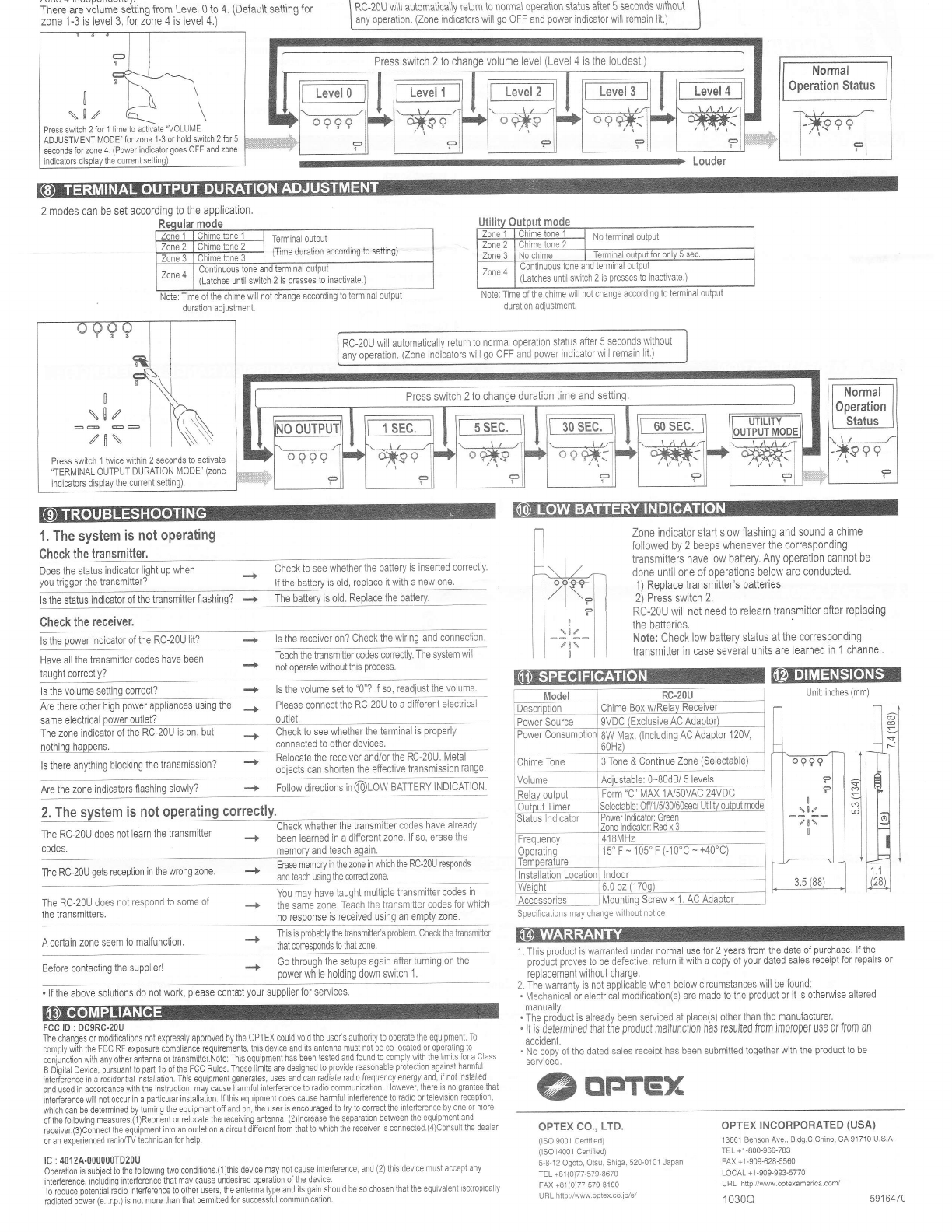
zone 1-3 is level 3, for zone 4 is level 4.) I Rc-20U wil\ automatically return to normal operation status after 5 seconds without I
I any operation. (Zone indicators will go OFF and power indicator will remain lit.) |
Normal
0peration Status
+t,
-*99 e€
I'i
Press swiich 2 fot 1 time to activate "VOLUI\,4E
ADJUSTIIENT |\.4ODE fof zone'l-3 or hold switch 2 fot 5
seconds for zone 4. iPower indicator goes oFF and zone
Press switch 2 to change volume level (Level 4 is the loudest.)
2 modes can be set according to the application.
Note: Time ofthe chime will not change according to terminal output
duraiion adjustment.
Note: Tlme of the chime will not change according t0 terminai oulput
duration adjustmeni.
(Latches until switch 2 is presses to inactivate.) (Latches until switch 2 is presses to inactivate.)
RC-20U will automatically return to normal operation status after 5 seconds without
any operation. (Zone indicators will go OFF and power indicator will remain lit )
1. The system is not oPerating
Check the transmitter.
Does the status indicator light up when
you trigger the transmitter? Check to see whether the battery is inserted correctly.
lf the battery is old, replace it with a new one.
ls the status indicator of the transmitter flashing? + The battery is old. Replace the battery'
Check the receiver.
ls the power indicator of the RC-20U lit? -+ ls the receiver on? Check the wiring and connection.
Zone indicator start slow flashing and sound a chime
followed by 2 beeps whenever the corresponding
transmitters have low battery. Any operation cannot be
done until one of operations below are conducted.
1 ) Replace transmitter's batteries.
2) Press switch 2.
RC-20U will not need to relearn transmitter after replacing
the batteries.
Note: Check low battery status at the corresponding
transmitter in case several units are learned in '1 channel
Have all the transmitter codes have been
t.r r^ht .^r16.tlv?
Teach the transmitter codes conectly. The system \vill
+ not oDerate without this process.
Press switch 1 twice within 2 seconds to activate
'TERIVINAL 0UTPUT DURATI0N |\,40DE' (zone
indlcaiors displav the current setting).
Press switch 2 to change duration time and setting.
-.f ls the volume set to "0"? lf so, readiust the volume @EIEEilEIEnEl
Unit: inches (mml
-20U to a different electrical
same electrical power outlet? outlet.
The zone indicator of the RC-20U is on, but + Check to see whether the terminal is properly
n^ihind h'nnan< connected to other devices.
''".
r' tn"..'vtni'g bhri'g th. t'.*'i*i.'z - Li3;"$3rtl'J".',iJl'ih31l3'.ttiHT3;lhuir$",1?!ry1
ls the volume setting correct?
Are the zone indicators flashing slowly? .+ Follow directions in @LOW BATTERY INDICATIoN
The RC-20U does not learn the transmitter
codes.
The RC-20U does noi respond to some of
the transmitters.
Description
Power Source 8W lVax. (lncluding AC Adaptor 120V
60Hz)
2, The system is not operating correctly. Check whether the transmitter codes have already
been learned in a different zone. lf so, erase the
memory and teach again.
The RC-20U gets reception in the wrong zone. Erase memory in the zone in which the RC-20U responds
and teach usinq the corect zone.
You rnay have taught multiple transmitter codes in
+ the same zone. Teach the kansmltter codes for which
no response js received using an empty zone.
3 Tone & Continue Zone (Selectable)
I Accessories
A certain zone seem to malfunction. Ths is Drobablv the (ansmitteis o.oblem. Check the rclsmitter
+mal coresponos I0 mal zone.
Before contacting the supplier! Go through the setups again after turning on the
power while holding down switch 1.
1. This product is warranted under normal use {or 2 years from the date of purchase. lf the
product proves 10 be defective, return it with a copy of your dated sales receipt for repairs oI
replacement without charge.
2. The wananty is not applicable when below circumstances will be found:
. Mechanical 6r electriial modification(s) are made to the product or it is otherwise altered
manuaily.
. The product is a ready been serviced at place(s) other than the manufacturer.
. lt is determined that the product malfunction has resuited from jmpr0per use 0r lr0m an
accident.
' No copy of the dated sales receipt has been submitted together with the product to be
servtced.
@oreTEx
. lf the above solutions do not work, please contat your supplier for services
FCC lD : DC9RC-20U
The changes or modifications not expressly approved by the OPTEX could void the usefs authoity io operatb the equipment. To
comply with the FCC RF exposure compliance requirements, this device and its antenna must not be co-locaied or opetating to
coniunction with anv othef antenna or transmitter.Note: This equipment has been tested and found to comply with the limits ior aclass
e Di;it"i D"ui".. o,;,**nt to pad 15 ofthe FCC Rules. These iimits are designed to provide reasonable pfotection againsi harmful
interi'erenie in a lesiOential instalJation. This equipmentgenerates, lses and can fadiate radjo frequency energy and, if not instailed
and used in accordance with the instruction, may €use harmful intederence lo radio communication. However, lhere is no grantee that
interference will not occur in a particular installation. lfthis equipment does cause harmful interference to radio or television re@ptlon,
which can be determined by turning the equipmenl off and on, lhe user is encouraged to lry to cotrect the intederence by one 0r more
ofthefollowingmeasures.(1)Reorientorrelocatethereceivingantenna.{2)lncreasetheseparationbetweentheequpmenland.
receiver(3)Co-nnect the equipment into an outlet on a circuit different from thal to which the receiver is connecled.(4)Consull the dea er
or af experienced radio/TV technician for help.
lC:4012A-000000TD20U
Operatjon is subiect to the following two conditions.(1)this device may not muse interference, and (2) this devlce must accept any
interferen@, including interference thal may cause undesired opelation ofthe device
To reduce potential r;dio interference to othef users, the antenna type and its gain should be so chosen that the equivalent isotropically
fadiated power (e.i.r.p.) is not more than that pemilted fof successiul communication
OPTEX CO., LTD.
(lSO 9001 Cedllied)
(1SO14001 Cediiied)
5-8-12 Ogoto, Otsu, Shiga, 520-0101 Japan
TEL +81(0)77-579-8670
FAX +81(0)77-579-8190
UBL http://www optex.co.jp/e/
OPTEX INCORPORATED (USA)
13661 Benson Ave., BLdg.C.Chino, CA 91710 U.S.A
TEL +1-800-966'783
FAX +1-909-628-5560
LOCAL +1-909-993-5770
URL http://www.optexamerica.com/
1o3oQ 5916470

Other Optex Receiver manuals

Optex RX-460 User manual

Optex

Optex RX-460 User manual

Optex TX-460 User manual

Optex

Optex TX-460 User manual

Optex Wireless 2000 RC-20U User manual

Optex

Optex Wireless 2000 RC-20U User manual

Optex BTR-5030 User manual

Optex

Optex BTR-5030 User manual

Optex Prowave Air-wave RX User manual

Optex

Optex Prowave Air-wave RX User manual

Popular Receiver manuals by other brands

Avenview VGA-C5-16 Specifications

Avenview

Avenview VGA-C5-16 Specifications

Sangean ATS-505 Product description & features

Sangean

Sangean ATS-505 Product description & features

AirMobi iReceiver user manual

AirMobi

AirMobi iReceiver user manual

M/A-Com P5100 Series Operator's manual

M/A-Com

M/A-Com P5100 Series Operator's manual

Sony STR-DA5700ES operating instructions

Sony

Sony STR-DA5700ES operating instructions

Onkyo TX-SR577 Quick setup

Onkyo

Onkyo TX-SR577 Quick setup

Topfield TF6500F user manual

Topfield

Topfield TF6500F user manual

Kenwood SLG-7 instruction manual

Kenwood

Kenwood SLG-7 instruction manual

JVC RX-8040B instructions

JVC

JVC RX-8040B instructions

Strong Digital Satellite Receiver user manual

Strong

Strong Digital Satellite Receiver user manual

AEG 4546 instruction manual

AEG

AEG 4546 instruction manual

Yamaha Aventage RX-A1020 owner's manual

Yamaha

Yamaha Aventage RX-A1020 owner's manual

resi-linx RL-BT120 installation manual

resi-linx

resi-linx RL-BT120 installation manual

Sony SAT-A2 Operating Instructions  (primary... operating instructions

Sony

Sony SAT-A2 Operating Instructions (primary... operating instructions

Pioneer VSX-LX50 operating instructions

Pioneer

Pioneer VSX-LX50 operating instructions

Marport M6 user guide

Marport

Marport M6 user guide

Explo X2 Series manual

Explo

Explo X2 Series manual

Yamaha RX-V557 owner's manual

Yamaha

Yamaha RX-V557 owner's manual

manuals.online logo
manuals.online logoBrands
  • About & Mission
  • Contact us
  • Privacy Policy
  • Terms and Conditions

Copyright 2025 Manuals.Online. All Rights Reserved.