1. The system is not
operating
Check the transmitter.
Does the status indicator light up when
you trigger the transmitter? Check to see whether the battery is inserted correctly.
If the battery is old, replace it with a new one.
Is the status indicator of the transmitter flashing? The battery is old. Replace the battery.
Check the receiver.
Is the power indicator of the Air-wave RX lit ? Is the receiver on? Check the wiring and connection.
Have all the transmitter codes have been
taught correctly? Teach thetransmittercodes correctly.Thesystem will
notoperatewithout thisprocess.
Are there other high power appliances using the
same electrical power outlet? Please connect the Air-wave RX to a different electrical
outlet.
The zone indicator of the Air-wave RX is on, but
nothing happens. Check to see whether the terminal is properly
connected to other devices.
Are the zone indicators flashing slowly? Follow directions in 8 LOW BATTERY INDICATION.
Is there anything blocking the transmission? Relocate the receiver and/or the Air-wave RX. Metal
objects can shorten the effective transmissionrange.
2. The system is not operating correctly.
The Air-wave RX does not learn the transmitter
codes.
TheAir-waveRX getsreceptionin the wrongzone.
Check whether the transmitter codes have already
been learned in a different zone. If so, erase the
memory and teach again.
Erasememoryin thezonein which theAir-waveRX responds
andteachusing thecorrectzone.
The Air-wave RX does not respond to some of
the transmitters.
You may have taught multiple transmitter codes in
the same zone. Teach the transmitter codes for which
no response is received using an empty zone.
Acertain zone seem to malfunction.
Thisisprobably thetransmitter’sproblem.Check the transmitter
thatcorrespondsto thatzone.
Before contacting the supplier! Go through the setups again after turning on the
power while holding down switch 1.
• If the above solutions do not work, please contact your supplier for services.
6 ADJUSTING THE TERMINAL OUTPUT DURATION
7 INSTALLATION
9TROUBLESHOOTING
8LOW BATTERY INDICATION
11 SPECIFICATION
13 WARRANTY
12 COMPLIANCE
FCC ID : DC9RG-10U
The changes or modifications not expressly approved by the OPTEX could void the user’s authority to operate the equipment. To
comply with the FCC RF exposure compliance requirements, this device and its antenna must not be co-located or operating to
conjunction with any other antenna or transmitter.Note:This equipment has been tested and found to comply with the limits for a Class
B Digital Device, pursuant to part 15 of the FCC Rules. These limits are designed to provide reasonable protection against harmful
interference in a residential installation. This equipment generates, uses and can radiate radio frequency energy and, if not installed
and used in accordance with the instruction, may cause harmful interference to radio communication. However, there is no grantee that
interference will not occur in a particular installation. If this equipment does cause harmful interference to radio or television reception,
which can be determined by turning the equipment off and on, the user is encouraged to try to correct the interference by one or more
of the following measures.(1)Reorient or relocate the receiving antenna. (2)Increase the separation between the equipment and
receiver.(3)Connect the equipment into an outlet on a circuit different from that to which the receiver is connected.(4)Consult the dealer
or an experienced radio/TV technician for help.
IC : CAN4012104524A
Operation is subject to the following two conditions.(1)this device may not cause interference, and (2) this device must accept any
interference, including interference that may cause undesired operation of the device.
To reduce potential radio interference to other users, the antenna type and its gain should be so chosen that the equivalent isotropically
radiated power (e.i.r.p.) is not more than that permitted for successful communication.
Zone indicator on Air-wave RX and TX start slow flashing
whenever the corresponding transmitters have low battery.
Any operation cannot be done until one of operations below
1) Replace transmitter’s batteries.
2) Press switch 2.
Air-wave RX will not need to relearn transmitter after
replacing the batteries.
Note: Check low battery status at the corresponding
transmitter in case several units are learned in 1 channel.
2011.04 DRAFT 5918380
OPTEX Co.,LTD.
5-8-12 Ogoto Otsu 520-0101, Japan
TEL.: +81(0)77 579 8700
FAX.: +81(0)77 579 7030
WEBSITE: www.optex.co.jp
East Coast Office
8510 McAlpines Park Drive, Suite 108
Charlotte, NC 28211 U.S.A.
TOLL-FREE: 800 877 6656
FAX.: +1 704 365 0818
WEBSITE: www.optextechnologies.com
OPTEX Technologies Inc.
Corporate Headquarters
3882 Del Amo Blvd., Suite 604
Torrance, CA 90503 U.S.A.
TOLL-FREE: 800 877 6656
FAX.: +1 310 214 8655
WEBSITE: www.optextechnologies.com
1. This product is warranted under normal use for 2 years from the Lot. number.
The Lot. number is printed on the sticker on back side of sensor. The first 2 digits stands
for year and the second 2 digits are week of manufacturing.
If you have questions, call to your sales representative.
2. The warranty is not applicable when below circumstances will be found:
• Mechanical or electrical modification(s) are made to the product or it is otherwise altered
manually.
• The product is already been serviced at place(s) other than the manufacturer.
• It is determined that the product malfunction has resulted from improper use or from an
accident. Physical damege will not be covered.
• No copy of the dated sales receipt has been submitted together with the product to be
serviced.
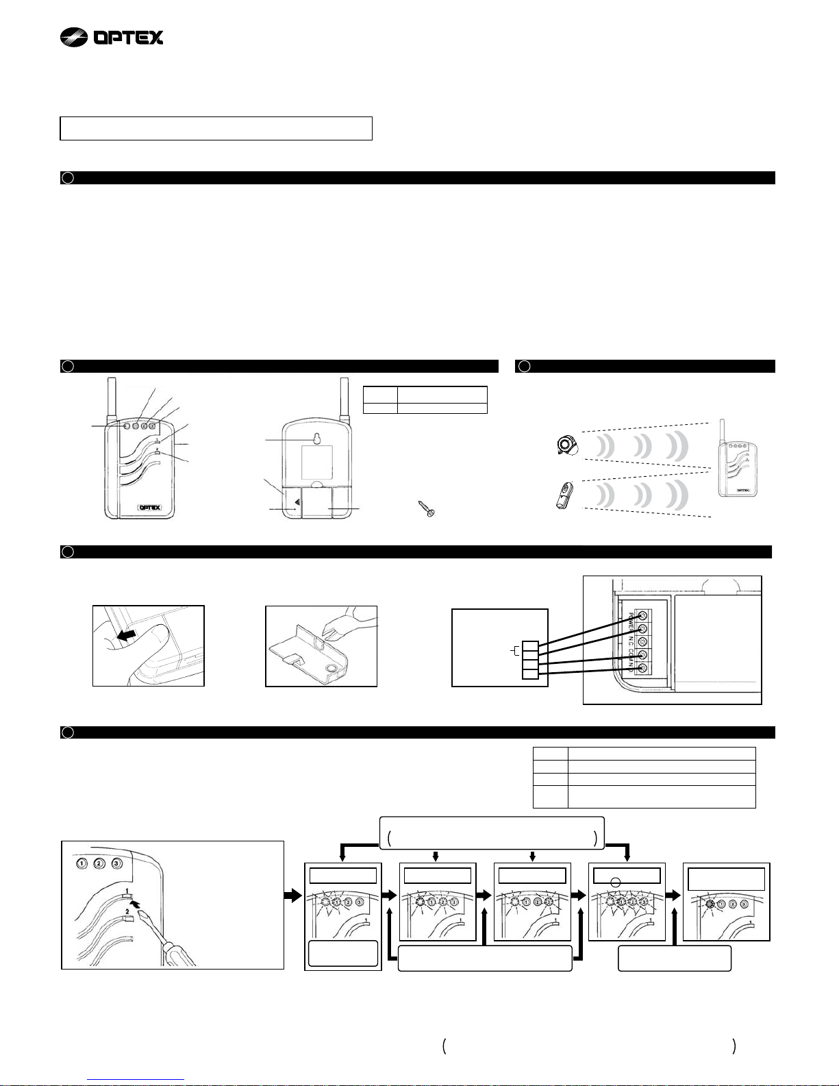
1231 2 3
•The terminal output duration can be set for zones 1-3 only as a
group. Zone 4 always latches until it is reset by pressing Switch 2.
• The factory setting is 1 sec.
Press Switch 1 twice within 2 seconds to activate the
output duration mode (zone indicators display the
current setting).
After 5 seconds, theAir-wave RX will automatically revert to normal operational
status (the zone indicators will go off and the power indicator will remain lit).
Press Switch 2 to toggle through settings.
1 SEC. 5 SECS. 30 SECS. 60 SECS. Normal
Operation Status
Mounting OnA Wall
Use the mounting screw on a wall. Leave
some length of the screw out for the
mounting hole of theAir-wave RX.
Desktop
Pull out the stand on the back of the
Air-wave RX and place it on any flat
surface.
Unit: inches (mm)
Product Series
Product Name
Model Number
Power Source
Relay Output
Output Timer
Status Indicator
Frequency
Operating Temperature
Installation Location
Weight
Accessories
ProwaveAir-wave RX
Single Relay Receiver
RG-10U
12~24VAC/DC
Standby: 30mA
Operating: 80mA
Form “C” MAX 1A/50VAC DC24VAC
Selectable: 1/5/30/60sec
Power Indicator: Green
Zone Indicator: Red × 3
418MHz
-10°C ~ +40°C
Indoors
120g
Mounting Screw × 1
Specifications may change without notice
10 DIMENSIONS
LONG FAN
below are conducted.