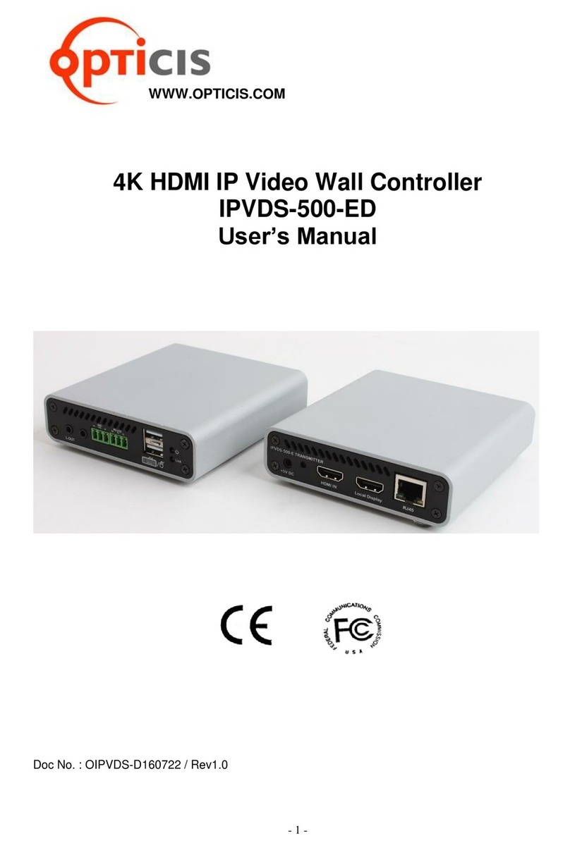
opticis IPVDS-700-ED User manual

- 1 -
IPVDS-700-ED
4K HDMI IP Video Wall Controller
User Manual
Doc No. : OIPVDS-180730EN / Rev1.0
WWW.OPTICIS.COM

- 2 -
Contents
1. Product Description
1.1 Main features
1.2 IPVDS-700 Control PC Application
2. Shipping Group
3. System Requirement
4. Exterior Description
5. Feature Description
5.1 Video over IP
5.2 Audio over IP
5.3 USB over IP
5.4 RS232 over IP
5.5 IR over IP (TBD)
5.6 Supporting Video Resolution
5.7 Supporting Audio Format
6. Installation
6.1 Hardware Installation Procedure
6.2 Reset and Factory Reset
7. Product Specification
8. Warranty

- 3 -
1. Product Description
IPVDS-700-ED, 4K HDMI IP Video Wall Controller, is an integrated control solution that enable to
play multi-source of audio/video (such as PC, Media Player, DVD and Blu-ray) on the video wall
system and multiple individual displays simutaneously.
This solution provides advanced audio/video matrix feature as well as control of video wall
system which divide high quality video source (4K 30Hz or 1080p 60Hz) into mutiple video walls
with using IPVDS-700-E (Encoder) and IPVDS-700-D (Decoder). It enables convinient system
configuration and control for AV System Integrator and Installer, and it also gives cost-efficiency
compared to complicated matrix system. For these reasons, IPVDS-700-ED provides optiaml
solution not only to large video wall system like control room, security, traffic control facility, but
also to general venues like conference room, classroom, presentation room, and worship facility.
Program provided for system control offers preview function of source video as well as various
display configurations like merging, overlaying, clearing, of displays with allocating audio/video
sources with simple drag and drop operation of mouse.
Figure 1. Connection Diagram

- 4 -
1.1 Main Features
-TCP/IP base IP network: Gigabit Ethernet
-Support up to 4K (3840x2160@30Hz 4:4:4 or 3840x2160@60Hz 4:2:0) input resolution
-Support up to 4K (3840x2160@30Hz 4:4:4) output resolution
-Supports Analog/HDMI audio input and output
-Fast switching time / low video latency
-Transmits HDMI/DVI video, audio, USB, RS-232, IR signal over IP network
-Provides HDMI loop-thru port for local display (Up to 4K 60Hz 4:2:0)
-Provides merge, overlay and split function on multiple video wall layout of PC program
-Supports up to 256 displays (16x16 - 4x64 - 1x256) video wall and multi-sources
-Supports M:N virtual matrix
-Supports 802.3af standard PoE (Power-over-Ethernet)
-Provides 5V/2A power adapter (Optional)
-Provides mounting bracket (model: OPSCB): VESA 75,100 standard (optional)
-Provides 1U rack (4 devices in 1 rack) & Power rack (PR5V-16: 16* 5V output) (optional)
1.2 IPVDS-700 Control PC Application
-PC application for controlling video wall and individual displays
-Provides drag and drop operation for host allocation
-Provides allocate, merge, split, overlay function on the layout management
-Provides preview screen before applying it to actual displays
-Provides up to 99 pre-sets for the user defined layout (save/load)
-Pre-set scheduling function: Sequential mode (dwell time based)
-Weekly mode (hourly/weekly based)
-Bezel compensation in 0.1mm
Figure 2. Software Main Screen
Note. Refer to IPVDS-Wall Controller manual for PC application manual

- 5 -
2. Shipping Group
□IPVDS-700-ED □HDMI cable 1.2m □Mini-USB cable □HDMI fixing screw
2.1 General Items
IPVDS-700-E Encoder
-One (1) HDMI male to male cable (1.2m).
-One (1) Mini-USB Cable for PC.
-HDMI cable fixing screw, 3-pin terminal block (male)
IPVDS-700-D Decoder
-One (1) HDMI male to male cable (1.2m).
-HDMI cable fixing screw, 3-pin terminal block(male)
2.2 Optional Items
-RS-232 cable: DB-9 male to 3-pin terminal block.
-AC / DC power adaptor: One (1) unit of 5V / 2A.
-Mounting bracket: OPSCB complying with VESA 75, 100 standard
-1U rack (4 in 1 rack).
-power rack (PR5V-16, 16*5V output).

- 6 -
3. System Requirement
3.1 Hardware Requirement
-Video source with HDMI output
-Display with HDMI input
-USB 2.0 port to use HID and USB storage feature
-No other special requirement for memory size, CPU speed or chipset
3.2 Software Requirement
-No special requirement
3.3 Network Requirement
-L2/L3 Gigabit management Ethernet switch is required for video matrix application.
-To apply correct operation, below features are required for L2/L3 gigabit management
Ethernet switch.
1) Gigabit Ethernet
2) Jumbo frame (8K or more)
3) L3 : IGMP and multicasting protocol
4) L2 : IGMP snooping
Note: With satisfaction of above requirement, certain network switch might not transmit
audio/video signal due to their performance.
-For bandwidth design, network topology and selection/setup of L2/L3 network switch,
visit Opticis website (www.opticis.com) or contact techsupp@opticis.com .
3.4 Control PC Requirement
-OS version check for IPVDS-Wallcontroller program
-Requirement: Windows7 or higher
3.5 Power Requirement
-IPVDS-700-ED supports 802.3af standard PoE (Power-over-Ethernet) and requires
support of 802.3af/802.3at Type 1 of network switch.
-IPVDS-700-ED is designed to give priority to power adapter when connecting external
+5V AC/DC power adapter.

- 7 -
4. External Description
4.1 IPVDS-700-E (Encoder)
Encoder front panel
Encoder back panel
ID
Name
Description
1
USB IN
Connection with PC USB port for Keyboard/Mouse use (HID)
2
L-IN
Line input port. Connection with line out audio
3
IR (TBD)
External IR cable port. IR Tx/Rx (Mode selection).
Function: * IR over IP, ** IR Guest Mode. (TBD)
4
RS-232
RS-232 control port
5
USB
Local keyboard/mouse connection. (support F/W Upgrade)
6
Power LED
‘Flashing’Booting and initializing status
‘ON’Completion of booting, operating status
‘OFF’Power OFF.
Link LED
‘Flashing’Ready status (Network connected), waiting for source
‘ON’Network link connection status of encoder and decoder
‘OFF’Network link disconnection status of encoder and decoder
7
+5V DC
5V DC power input. 5V/2A, 3.5x1.35mm adapter connection
Higher priority than PoE, PoE won’t operate when using adapter
8
RESET
‘Short push’Re-booting
‘Long push’Factory reset when pushing more than 3 seconds
9
RJ45
LAN port. Supports 1000Base-T, 802.3af PoE
10
HDMI IN
HDMI input. Standard embedded UHD EDID
11
Local Display
HDMI output. Output HDMI IN input signal

- 8 -
4.2 IPVDS-700-D Decoder
Decoder front panel
Decoder back panel
ID
Name
Description
1
L-OUT
Line output port. Connection with line-in audio
2
IR (TBD)
External IR cable port. IR Tx/Rx (Mode selection).
Function: * IR over IP, ** IR Guest Mode. (TBD)
3
RS-232
RS-232 control port
4
USB
Local keyboard/mouse connection. (support F/W Upgrade)
5
Power LED
‘‘Flashing’Booting and initializing status
‘ON’Completion of booting, operating status
‘OFF’Power OFF.
Link LED
‘Flashing’Ready status (Network connected), waiting for source
‘ON’Network link connection status of encoder and decoder
‘OFF’Network link disconnection status of encoder and decoder
6
+5V DC
5V DC power input. 5V/2A, 3.5x1.35mm adapter connection
Higher priority than PoE, PoE won’t operate when using adapter
7
RESET
‘Short push’Re-booting
‘Long push’Factory reset when pushing more than 3 seconds
8
RJ45
LAN port. Supports 1000Base-T, 802.3af PoE
9
HDMI OUT
HDMI output.

- 9 -
5. Feature Description
5.1 Video over IP
IPVDS-700-ED provides matrix and video wall feature with multi-cast
connection and IPVDS-Wallcontroller program or API can be provided for this
Each encoder and decoder requires to be assigned their own IP address, and
each encoder can be connected to single/multiple decoder(s).
Figure 3. KVM Matrix
Figure 4. Video Wall
Note 1. Fast switching operates when resolution and mode of encoders are all same.
Note 2. Decoder can get connected to one encoder concurrently.

- 10 -
5.2 Audio over IP
IPVDS-700-E supports audio input of both HDMI Audio and Analog Line In.
HDMI/Analog Line In audio will be delivered to decoder by Hot-plug of
Analog Line In port. IPVDS-700-D will output delivered audio from encoder
through HDMI and Analog Line Out simultaneously.
Analog Line In audio gets priority when receiving both HDMI audio and
Analog Line In input. When both audio channels get connected, encoder will
only deliver Analog Line In audio to the decoder, and HDMI audio will not be
delivered.
HDMI Audio connected, Analog Line In disconnected
Both HDMI Audio and Analog Line In connected
Figure 5. Audio over IP

- 11 -
5.3 USB over IP
IPVDS-700-ED offers USB Virtual Hub feature which makes USB device
connected on decoder (remote site) operates on PC connected with encoder.
-Supporting devices: HID, storage and more
-Concurrent connection: 1 encoder x N Decoder <= 5 USB devices
Figure 6. USB over IP
5.4 RS232 over IP
Figure 7. RS232 over IP
RS232 over IP: RS-232 signal transmission between encoder ↔decoder
( default is 115200-8n1 )
RS232 Guest Mode: Manage RS-232 input/output signal from encoder/decoder on
control PC

- 12 -
5.5 IR over IP / IR Guest mode (TBD)
Figure 8. IR over IP
IR over IP: IR signal transmission between encoder ↔decoder
IR Guest Mode: Manage IR input/output signal from control PC
5.6 Supported Resolution
Spec
Support
Interlace mode
O
HDMI 1.4b up to 1080p
O
HDMI 1.4b 2160p 30Hz
O
HDMI 1.4b 3D
O
HDMI 1.4b deep color
O
HDMI 2.0a 2160p 60Hz
O
Note. 1 Only 2160p 60Hz YUV420 input
Note. 2 Will do horizontal half down scale and convert 2160p 60Hz
YUV420 input to 2160p 30Hz output
VESA DVI
up to 1920x1200 60Hz
Pixel clock < 165MHz
O
VESA VGA
up to 1920x1200 60Hz
Pixel clock < 150MHz
O
Maximum Frame Rate
full frame rate up to 60fps

- 13 -
5.7 Supported Audio Format
Audio Format
Support
Dolby Digital 5.1 ch
O
Dolby Digital Plus
O
Dolby TrueHD
O
DTS 5.1 ch
O
DTS-HD High Resolution Audio
O
DTS-HD Master Audio
O
Linear PCM 2 ch 44.1/88.2/176.4/32/48/96/192 kHz
O
Linear PCM 5.1 ch 44.1/88.2/176.4/32/48/96/192 kHz
O
Linear PCM 7.1 ch 44.1/88.2/176.4/32/48/96/192 kHz
O

- 14 -
6. Installation
6.1 Hardware Installation Procedure
Important: Follow below steps for installation procedure. If not installed properly,
malfunction could happen.
Step 1
Unpack the package.
Step 2
Turn on PC, display, network switch (L2/L3).
Step 3
Turn on the PC for IPVDS-Wallcontroller program and connect LAN cable (Cat5e/CAT6) to
the network switch.
Step 4
Connect HDMI cable from display source to HDMI IN port of IPVDS-700-E (Encoder).
Step 5 (optional)
Connect enclosed USB cable from PC to USB port of IPVDS-700-E (Encoder). This step can
be skipped if not using local/remote control of keyboard and mouse.
Step 6 (optional)
Connect HDMI cable from IPVDS-700-E loop-thru port to local HDMI display.

- 15 -
Step 7
Connect LAN cable (CAT5e/6) from IPVDS-700-E (encoder) to RJ45 port of network switch.
Step 8
Connect HDMI cable from IPVDS-700-D (decoder) HDMI OUT port to Display.
(Connect keyboard and mouse for remote control.)
Important: IPVDS-700-D has to be connected to each of video wall displays in order.
Refer to display placement section for more detailed information.
Step 9
Connect LAN cable (CAT5e/6) from IPVDS-700-D (decoder) to network switch.
Step 10 (optional for non-PoE network switch user)
Plug +5V power adapters to both IPVDS-700-E (encoder) and IPVDS-700-D (decoder).
Note: When using, PoE supported network switch, ignore step 10.
6.2 Reset and Factory Reset
♦Reset (short key): Device will reboot when pressing reset button shortly.
♦Factory Reset (Long key): Press and hold reset button for approximately 5 seconds, then
LED of device will be flashing for factory reset. It will reboot automatically after
factory reset.
Note: Do not unplug LAN cable (when using PoE network switch), or power adapter while
running factory setting

- 16 -
7. Product Specification
When using PoE feature, maximum transmission length over LAN cable can decrease.
(ex: LSIS CAT5e UTP single wire: 90~100m)
Description
Network
TCP/IP based IP network: 1000 Base-T Ethernet with CAT5e/CAT6
Network media
* UTP CAT5e, 6 cable Max 100m
Jumbo Frame
8,000
Input Resolution
Max 3840x2160@30Hz 4:4:4 or 3840x2160@60Hz YCbCr4:2:0
Output Resolution
Max 3840x2160@30Hz 4:4:4
Video Wall
Up to 256 (16x16, 4x64, 1x256, etc.) Video Wall with multi-sources
Virtual IP Matrix
Supports Rows by Columns Virtual Matrix with individual displays
Multicast streaming
1 to N (up to 256 RXs)
Video Interface
HDMI 1.4 and DVI 1.0
HDCP
HDCP 1.4 and 2.2
Video latency
< 1 frame
Fast switching
< 2 seconds
Data rate (changeable)
50, 100, 150, 200Mbps(default) and Best
Video Interface
IPVDS-700-E
Input: 1 HDMI Input
Output: 1 HDMI Output
IPVDS-700-D
Output: 1 HDMI Output
Analog Audio Interface
IPVDS-700-E
LINE IN 1 port
IPVDS-700-D
LINE OUT 1 port
USB
IPVDS-700-E
Host: 2 x USB A type
Client:1 x mini USB B type
IPVDS-700-D
Host: 2 x USB A type
IR (TBD)
IR Tx/Rx (Mode select)
RS-232
3 Pin Terminal block for Control Authority (Externally)
EDID
Built-in EDID & EDID Read/Write (decoder read only)
Dimension
112 x 28 x 104mm (WHD)
Power
PoE : IEEE 802.3af(15.4W). * option: Adapter 5V/2A
Power Consumption
TX < 6W
RX < 5W
Operating Temperature
0 ~ 50°C
Storage Temperature
-20 ~ 60°C
Certification
FCC, CE, KC

- 17 -
8. Warranty
1 (One) Year Warranty
Opticis warrants IPVDS-700-ED, HDMI IP Video Wall controller to be free from defects in
workmanship and material, under normal use and service, for a period of one(1) year from the
date of purchase from Opticis or authorized resellers.
To request repair or service from Opticis, customer shall not open the product, nor place any part
of IPVDS-700 without assistance from Opticis. Keep serial number sticker on the device.
Opticis has no responsibility for any software, firmware, information or memory data of customer
contained in, stored on, or integrated with any returned to Opticis for repair
(Under warranty or not)
1. Free Repair
-Faulty IPVDS-700 under normal use in warranty in period
2. Customer Paid Repair
-Faulty IPVDS-700 but out of warranty period
-Faulty caused by negligence and/or intention of customer
-Faulty caused by voluntary alternation or repair without approval from Opticis
-Faulty caused by natural calamities
-Faulty caused by connection with other faulty device
If a product does not work as warranted during applicable warranty period, Opticis shall, at its
option and expense, repair the defective product or part, deliver to customer an equivalent
product or part to replace the defective item refund to purchase price for the defective product.
All products that are replaced will become the property of Opticis. Replacement products may be
new or reconditioned.
Dispose of Old Electrical & Electronic Equipment
(Applicable in the European Union and other European countries with separate systems)

- 18 -
This symbol on the product or on its packaging indicates that this product shall not be
treated as household waste. Instead it shall be handed over to the applicable
collection point for the recycling of electrical and electronic equipment. By ensuring
this product is disposed of correctly, you will help prevent potential negative
consequences for the environment and human health, which could otherwise be
caused by inappropriate waste handling of this product.
The recycling of materials will help to conserve natural resources. For more detailed information about
recycling of this product, please contact your local city office, your household waste disposal service
or the shop where you purchased the product.
Table of contents
Other opticis Controllers manuals
Popular Controllers manuals by other brands

Sloan
Sloan PWT MCR 4014 INSTALLATION AND PROGRAMING INSTRUCTIONS

Komaes
Komaes KC5 instruction manual

Remote Control Technology
Remote Control Technology Muirhead 11337 product manual

Mitsubishi Electric
Mitsubishi Electric MELSERVO-J5 MR-J5-G Series user manual

Lenze
Lenze 482 operating instructions

ZAFFER
ZAFFER MINI user manual