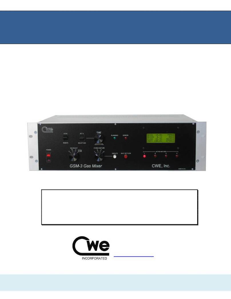
CWE GSM-4 User manual

GSM-4
4-Channel Programmable Gas Mixer
©CWE 2023
Read instructions carefully before operating this device.
This device is not to be used for Human Life Support applications.
To avoid possible electrical shock, do not operate this device if is wet or has had
liquids spilled onto it.
Service or calibration procedures should only be performed by qualified
personnel familiar with the electrical hazards of line-powered devices.
Instruction Manual
www.cwe-inc.com

GSM-4 Gas Mixer Instruction Manual 2
©2023 CWE, Inc.
STATEMENT OF WARRANTY
IF THIS INSTRUMENT FAILS WITHIN A PERIOD OF ONE YEAR FROM THE DATE OF
DELIVERY OR INSTALLATION, CWE, INC. WILL, AT ITS OPTION, REPAIR OR REPLACE IT
FREE OF CHARGE TO THE PURCHASER. THIS WARRANTY EXCLUDES DAMAGE
INCURRED THROUGH ABUSE OR ACCIDENT AND CONSUMABLE ITEMS OR
COMPONENTS SUCH AS BATTERIES. CWE, INC. DOES NOT ASSUME ANY LIABILITY FOR
ANY CONSEQUENTIAL DAMAGES RESULTING FROM THE USE OR MISUSE OF THIS
INSTRUMENT. THIS WARRANTY IS APPLICABLE ONLY TO THE ORIGINAL PURCHASER
OF THE INSTRUMENT AND IS NON-TRANSFERRABLE.
IF YOU HAVE A PROBLEM
Please call or write describing your problem. We can often identify what is wrong and suggest a
solution without recourse to returning the device. Defective units under warranty should be
returned to the factory along with a note describing the nature of the fault. Every effort will be
made to ensure prompt repair or replacement of the device.
FACTORY SERVICE
Out of warranty or damaged instruments may be returned to the factory postage prepaid for
service at prevailing rates. Upon request, a written or verbal quotation for such service will be
issued after examination of the unit but prior to commencing repairs or service. Address requests
for service or technical information to:
CWE, Incorporated
Technical Support Department
www.cwe-inc.com
TEL (610)642-7719
LIFE SUPPORT POLICY
Instruments manufactured by CWE, Incorporated are not authorized for use as critical
components in humanlife support devices or systems. "Life support devices or systems", as used
herein, are devices or systems whose failure to perform, whether through misuse, failure, or
proper operation, can reasonably be expected to result in significant injury to the operator or
subject persons.
USER INFORMATION:
Base Unit Serial Number: _______________
Gas: Channel A_____, Channel B_____, Channel C_____, Channel D_____
Flows: Channel A_____, Channel B_____, Channel C______, Channel D______
GSM-4-CommMX Software version: __________________
Gas correction factors (see Note): enabled_____ not used_____
NOTE: If gas correction factors (K-Factors) are not used, this indicates the flow controllers for each channel are
pre-calibrated with a specific gas for the highest accuracy. If enabled AND not used are checked, the flow
controllers are calibrated using a specific gas, but the user has the ability to make small corrections using K-
factor adjust.
This document last updated May 26, 2023

GSM-4 Gas Mixer Instruction Manual 3
©2023 CWE, Inc.
TABLE OF CONTENTS
1.0 QUICK START GUIDE..............................................................................................4
2.0 INTRODUCTION.......................................................................................................6
3.0 SETUP......................................................................................................................7
4.0 OPERATION.............................................................................................................8
4.1 CREATING A GAS MIXTURE (LOCAL MODE)........................................................8
4.2 NOTES ON GAS MIXTURES ...................................................................................9
4.3 INDICATOR LIGHTS...............................................................................................10
4.4 IMMEDIATE ACTION CONTROLS.........................................................................10
4.5 LOCAL / REMOTE SWITCH...................................................................................10
5.0 REAR PANEL CONNECTIONS..............................................................................11
6.0 USING CORRECTION FACTORS..........................................................................11
7.0 FLOW ALARMS......................................................................................................13
8.0 SPECIFICATIONS ..................................................................................................14
9.0 GAS CHARACTERISTICS......................................................................................15
10.0 GSM-4-CommMX SOFTWARE.............................................................................16
11.0 Appendix A: GSM-4 Communication protocols.....................................................23
Figure 1: GSM-4 Gas Mixer front panel ...................................................................................................................6
Figure 2: GSM-4 LCD panel.....................................................................................................................................8
Figure 3: GSM-4 LCD panel showing Total Flow ....................................................................................................9
Figure 4: GSM-4 Alarm display..............................................................................................................................13
Figure 5: GSM-4-CommMX Mode selection) ........................................................................................................16
Figure 6: GSM-4-CommMX screen (MODE 1: Four-channel mixer mode shown)...............................................17
Figure 7: Independent (MODE 2: all channel flows independently set)..................................................................17
Figure 8: Mimic (MODE 3: Channel 4 = Total Flow of mixture)...........................................................................18
Figure 9: Mass Flow Controller values entered for each channel............................................................................18
Figure 10: Drop-down Configuration menu. ...........................................................................................................19
Figure 11: Gas selection drop-down menu..............................................................................................................19
Figure 12: Mixture configuration panel, GSM-4 mode...........................................................................................20
Figure 13: Mixture configuration panel, Independent mode. ..................................................................................20
Figure 14: Mixture configuration panel, Mimic mode. ...........................................................................................20
Figure 15: Timed experiment setup using the Sequencer........................................................................................21

GSM-4 Gas Mixer Instruction Manual 4
©2023 CWE, Inc.
1.0 QUICK START GUIDE
This section provides a short guide to setting up and operating the GSM-4 Gas
Mixer. A more detailed description will be found in later sections of this instruction
manual.
Equipment set-up: Place the GSM-4 in a convenient location. If a computer is to
be used for remotely controlling the GSM-4, it should be
located nearby.
Connect the tubing: Connect the compressed gas sources to the gas inlets on the
rear panel. Note that these are “one-touch” press-in tubing
connectors. The gas outlet supplies the mixed gas.
Connect the cables: Connect the serial port cable between your computer and the
and the GSM-4 rear panel connector. If your computer does
not have a serial port, use the supplied USB-Serial adapter.
Install the software: Insert the GSM-4-CommMX USB flash-drive into your
computer. Browse to setup.exe on the USB flash-drive.
Follow the instructions to install the program.
Start GSM-4-CommMX: From the start menu, choose programs, and locate GSM-4-
CommMX. Select it to run the program.
Select config file: A dialog box will open asking you to select a configuration file.
Select default.txt to select a generic configuration file, or
cancel to go directly to the main screen.
Configure COM port: Locate the COM PORT text box on the screen. This drop-
down text box will show all available COM ports (serial ports)
on your computer. Select the one you want to use. The
program will not work if the correct COM port is not selected!
Set flow ranges: If not already displaying the channel flow ranges (bottom right
of screen), enter them now.
Power up the GSM-4: Turn on the GSM-4 power. After an introductory message, the
LCD will display the main screen. Select LOCAL if you want to
begin making settings from the front panel, or REMOTE if you
want to set up the GSM-4 from your computer.
Ready to go! Using either the front panel controls (LOCAL mode) or the
GSM-4-CommMX software (REMOTE), select the gasses
you have connected to the inlets. Adjust the percentages
for each, and set the total flow desired.
Configurations: The GSM-4 allows you to store up to four mixtures, which can
be immediately accessed using the stored mixture knob. The
GSM-4-CommMX software similarly allows setting up four
mixtures. These sets of mixtures can be saved as
configuration files. Use the configuration menu at the top of
the screen to save or load these files.
Save on exit: Use the EXIT pushbutton on the screen to close the program.
A dialog box will open, asking you to save a configuration file.
Select an existing file, or create a new one, or select cancel to
exit without saving a configuration file.

GSM-4 Gas Mixer Instruction Manual 5
©2023 CWE, Inc.
Operating tips: Give your configuration files meaningful names to allow easy
retrieval and use in the future. A few sample files are included
as examples.

GSM-4 Gas Mixer Instruction Manual 6
©2023 CWE, Inc.
2.0 INTRODUCTION
The GSM-4 Gas Mixer allows you to easily create accurate, custom gas blends
using up to four different gasses. All parameters (gas type, percent of each gas in
the output mixture, and total flow) can be set using the front panel controls, but can
most conveniently be set using the provided GSM-4-CommMX software. Most
GSM-4 configurations use Mass Flow Controllers calibrated for a specific gas (see
User Information on page 2).
A typical application of the GSM-4 is to generate gas mixes for hypoxia,
hypercapnia, or other respiratory gas studies. Because these studies often involve a
low concentration of one gas relative to the other gas components, one GSM-4 flow
channel normally uses a different range flow controller. A typical configuration might
be as follows (your instrument may be different):
Note: Each GSM-4 is customized to the user’s requirements with the
appropriate mass flow controllers installed (see page 2 for your
configuration). Examples shown in this manual will probably differ from
yours.
Channel:
Gas
Nominal Range
Usable Range
GAS 1
N2
0 –10,000 ml/min
100 –10,000 ml/min
GAS 2
O2
0 –5,000 ml/min
50 –10,000 ml/min
GAS 3
CO2
0 –1000 ml/min
10 –1000 ml/min
GAS 4
He
0 –1000 ml/min
10 –1000 ml/min
For the best accuracy, any of the channels should only be set within the usable
range for that channel.
The GSM-4-CommMX software provided allows the user to save any number of
pre-set configurations for later use. These mixtures can then be downloaded and
run on the GSM-4 itself.
Figure 1: GSM-4 Gas Mixer front panel

GSM-4 Gas Mixer Instruction Manual 7
©2023 CWE, Inc.
3.0 SETUP
Setting up the GSM-4 Gas Mixer is straightforward. The following instructions
assume that a computer with a standard serial port is available, or a USB-Serial
adapter cable is used.
1. Install the GSM-4 Gas Mixer in a location convenient to the gas sources, and
near the computer that will be used with it. The unit can be rack mounted if
desired.
2. Connect your pressurized gasses to the GAS 1, GAS 2, GAS 3, and GAS 4ports on
the rear panel. These ports require 0.25” (6.35mm) O.D. semi-flexible tubing,
which makes a press-fit connection. To disconnect any of the tubing connections,
press in on the outer ring of the connector and pull out the tubing. Gas pressures
should be in the range of 20 - 50 psi (1.4 –3.4 bar).
Note: Most GSM-4’s will be configured for specific gasses, which must be
connected to the appropriate inlet.
3. Connect the GAS OUTLET port using the same type tubing or use one of the hose-
barb adapters included with the system.
4. Connect the supplied serial port cable from your computer to the 9-pin female
RS232 port on the rear of the GSM-4. If your computer does not have a serial
port, install and use the supplied USB-Serial adapter. This adapter will create a
virtual COM port, whose COM number can be located at: Control Panel /
System / Device Manager /Ports (COM & LPT) / USB-Serial COM4
(typical, but your COM port number may be different).
5. Install the GSM-4-CommMX software on your PC. Insert the flash-drive in your
computer and run Setup.exe. We recommend accepting the default file
locations.
6. When the GSM-4 is turned on, select LOCAL to set up the instrument from the
front panel, or REMOTE to use the GSM-4-CommMXsoftware. Be sure to set the
COM port to the actual port used on your computer.

GSM-4 Gas Mixer Instruction Manual 8
©2023 CWE, Inc.
4.0 OPERATION
The instructions below describe the procedure for setting up gas mixtures and
running them from the instrument itself. The operation of the GSM-4-CommMX
software is described later.
Figure 2: GSM-4 LCD panel
4.1 CREATING A GAS MIXTURE (LOCAL MODE)
Be sure the LOCAL /REMOTE switch is set to LOCAL.
Up to four custom gas mixtures can be created and stored in the GSM-4. To create,
edit, or run any of these, use the STORED MIXTURE knob. When any of the stored
mixtures is selected, its current settings will be displayed on the LCD panel.
Selecting gasses –Using the GAS SELECT knob, select either A, B, C, or D. While
holding the SELECT GAS /SET %lever switch in the SELECT GAS position, rotate the
ADJUST knob until the desired gas is shown on the display. Perform this procedure
to set gasses A, B, C, and D.
Note: Most GSM-4’s will be configured for specific gasses for each of the
four channels.
Setting gas percentages –Each gas can be set to anywhere in the 0 –100%
range, with 0.1% resolution. The total should add up to 100%, or the flows will be
inaccurate. The ERROR light will turn on and stay on until the gas fractions add up to
100 percent. To set a percentage, first point to A, B, C, or D using the GAS SELECT
knob. While holding the SELECT GAS /SET %switch in the SET %position, rotate the
ADJUST knob until the desired percentage is shown on the display. Repeat for the
other gasses. Remember that the total should add up to 100%!
Setting flow –The GSM-4 allows you to set the total flow of the mixture only.
Individual gas flows are computed based on the selected percentage, and shown on
the display, but the user cannot change these directly.
To set the total flow, rotate the SELECT GAS knob to the TOTAL FLOW position. Use
the ADJUST knob to set the flow, which will be displayed on the LCD panel.

GSM-4 Gas Mixer Instruction Manual 9
©2023 CWE, Inc.
Figure 3: GSM-4 LCD panel showing Total Flow
Storing the mixture -- After a mixture is configured, press the EXECUTE pushbutton,
which will store the mixture and start it running. Press the SHUT OFF FLOW
pushbutton to stop the flow. The mixture is now stored in non-volatile memory, and
will be available even if the instrument has been turned off, and then on again.
The four stored mixtures can be created and stored as described above, and can be
selected and executed any time the instrument is used.
4.2 NOTES ON GAS MIXTURES
No flowmeter or flow controller is “ideal”; i.e., it does not operate linearly over a
zero –full scale range. The range of operation is known as the turndown ratio. This
is simply the ratio of full-scale to minimum usable range. In the case of the GSM-4
controllers, this turndown ratio is approximately 100:1. For example, a 1000sccm
(standard cc/minute) controller can accurately operate over a 10 –1000sccm range.
The practical result of this information is that all possible combinations of mixtures
and flows may not be accurate if any of the gas channels fall outside of the usable
range for that channel. If any of the computed flows falls below the minimum usable
flow, the TOTAL FLOW should be increased to raise the channel flow above the
usable lower limit. The following example illustrates this condition:
Desired flow mixture, total flow = 500 ml/min, initial settings:
Channel
Flow Range
Min usable
flow
Percent of mix
Computed channel flow
GAS 1 (N2)
5000 sccm
50 sccm
73.0%
365 sccm (good!)
GAS 2 (O2)
2000 sccm
20 sccm
21.0%
105 sccm (good)
GAS 3 (CO2)
500 sccm
5 sccm
0.5%
2.5 sccm (bad!)
GAS 4 (He)
4000 sccm
40 sccm
5.0%
25 sccm (bad!)
NOTE: Flows shown as sccm (Standard cc/min)
The flows for GAS 3and GAS 4fall below the usable minimums. To correct this,
increase the total flow to move these individual flows into the usable ranges.

GSM-4 Gas Mixer Instruction Manual 10
©2023 CWE, Inc.
4.3 INDICATOR LIGHTS
The various indicator lights give important information about the operation of the
GSM-4 Gas Mixer.
Active Mixture lights –These four red LED’s indicate which mixture is currently
selected by remaining steadily on. A blinking ACTIVE MIXTURE led indicates that a
particular mixture is currently running (flow is being delivered). Even while one
mixture is running, the STORED MIXTURE knob can be used to select another mixture
for configuration. In this case, one of the LEDs will be blinking (that mixture is
running), and another is steadily on (indicating that that mixture is being displayed
for editing, etc.).
Running light –This green LED will turn on when gas is actually flowing; i.e., a
mixture is currently running.
Error light –This red LED will indicate setup errors, such as when the gas
percentages do not add up to 100%.
4.4 IMMEDIATE ACTION CONTROLS
As described above, the EXECUTE pushbutton will immediately cause the currently
selected mixture to run. Conversely, pressing the SHUT OFF FLOW pushbutton will
immediately shut off the flow controllers.
4.5 LOCAL / REMOTE SWITCH
Set this switch to LOCAL to perform gas mixture setup and execution from the
GSM-4 front panel. Set this switch to REMOTE to use the GSM-4-CommMX software
to remotely control the instrument. Note that in remote mode, the ACTIVE MIXTURE
led’s are not automatically on, indicating that the STORED MIXTURE switch setting is
ignored, since this function is performed by the software.

GSM-4 Gas Mixer Instruction Manual 11
©2023 CWE, Inc.
5.0 REAR PANEL CONNECTIONS
Gas Inlets –These ports are used to connect any of the four inlet gasses. The
connectors are compatible with ¼” OD semi-flexible pneumatic tubing (urethane or
similar). Press in the outer ring of the connector to withdraw the tubing.
Gas Outlet –This port provides the gas mixture created by the GSM-4.
Note: Your GSM-4 may have one or more additional Outlets. This allows one or
more gas channels to be used independently.
Fuse –In case this fuse blows, replace it with one of the same current and voltage
rating as the original. If the fuse blows repeatedly, the instrument should be
returned for service.
Serial Port –The RS232 serial port uses a standard 9-pin D-sub connection. This
port should be connected to your computer using a straight-wired cable (not a
crossover or modem cable). Use the supplied USB-Serial adapter if a true serial
port is not available.
Analog Outputs –These BNC jacks provide an analog voltage corresponding to
the flow rate of each of the four gasses in the current gas mixture. The range of this
signal is 0 –5V, where 5V is the full-scale range of the particular flow channel.
6.0 USING CORRECTION FACTORS
Different gasses have different physical properties (density, viscosity, etc.) and thus
behave differently with Mass Flow Meters and Controllers (MFCs). Most GSM-4
systems are shipped with MFC’s pre-calibrated for specific gasses, which gives the
best accuracy.
When more than one gas is to be used on a gas flow channel, that MFC is typically
calibrated for nitrogen, and a correction factor (also called K-factor) is applied to
match the new gas. If K-factors are enabled on your GSM-4 system (see page 2,
User Information), these corrections will be applied when you select a gas, either
from the front panel or using the GSM-4-CommMX software.
Note: Most GSM-4’s will be configured for specific gasses, which must be
connected to the appropriate Gas Inlet. These mass flow controllers are factory
calibrated using the actual gasses, and DO NOT use correction factors.
Some systems using specific, pre-calibrated gasses also allow user-adjustable
flow corrections. See: User Information

GSM-4 Gas Mixer Instruction Manual 12
©2023 CWE, Inc.
ADJUSTING CORRECTION FACTORS
Although flows generated using K-factors are generally accurate to within +4%, you
can adjust them to provide the best accuracy under the specific laboratory
conditions of the user. The procedure described below explains how to do this.
1. Set up and run a gas mixture using the gas you want to calibrate. For example,
5.0% CO2, 95% nitrogen.
2. Switch to LOCAL CONTROL.
3. Monitor the actual output concentration of the target gas (CO2).
4. Press the ADJUST KNOB to display the “Adjust K-factor” menu:
5. Rotate the ADJUST KNOB until the desired gas is displayed:
6. When the target gas is shown, press the ADJUST KNOB. The following screen will
appear, showing the current K-factor for that gas:
7. Rotate the adjust knob to increase or decrease the displayed K-factor. Increasing
it will cause a higher flow of that gas at the outlet, and decreasing it will result in a
lower flow. In the example above, if a 5.0% CO2mixture is set up, but the actual
measured concentration reads 4.6%, try increasing the K-factor by 13 (about 8%)
to 180. After making this change, press the ADJUST KNOB to accept and store this
change. The GSM-4 will re-start, and apply the new K-factor.
8. After re-starting, the previously run test gas mixture should be displayed. Run it,
and note the output gas concentration. If the concentration still needs
adjustment, repeat the above procedure activated by pressing the ADJUST KNOB.
After this procedure is completed, the K-factor is stored and will be applied
automatically whenever the GSM-4 is used.
Note: Even with pre-set gasses, you can use this same procedure (if K-factors are
enabled) to make small changes on any gas channel. Stored values will be 100, and
the user can increase or decrease the scale factor within the range 10 –255.
Set gas K-factor
Select gas: AIR
SHUT OFF to exit
KNOB to accept
Set gas K-factor
Select gas: CO2
SHUT OFF to exit
KNOB to accept
Set gas K-factor
CO2 K = 167
SHUT OFF to exit
KNOB to accept

GSM-4 Gas Mixer Instruction Manual 13
©2023 CWE, Inc.
7.0 FLOW ALARMS
The GSM-4 Gas Mixer is equipped with an alarm system to detect a discrepancy
between the requested flow and the actual output flow from any of the four Mass
Flow Controllers (MFC’s). The major trigger conditions for this alarm are:
1. There is zero output flow from any MFC.
MOST LIKELY CAUSE: A gas supply tank is empty, supply valve is shut off, etc.
2. The output flow is substantially different (higher or lower) than the requested flow.
MOST LIKELY CAUSE: Low or varying gas supply pressure, or (rarely!) a failed MFC.
When an ALARM is triggered, the 4th line of the LCD will show which gas channel is
at fault. This message will be dismissed after ten seconds and return the display to
normal. You can clear the message immediately by pressing the ADJUST KNOB.
Figure 4: GSM-4 Alarm display
ENABLING OR DISABLING FLOW ALARMS
Although we recommend using the built-in alarms, they can be turned off if desired.
One possible reason might be that a very rapid gas switching routine is used (see:
Sequencer). If the gasses are cycled faster than once every three seconds, a false
alarm could be issued.
To Disable or Enable Alarms –Simultaneously push and hold the ADJUST
KNOB and the SHUTOFF FLOW pushbutton while switching POWER on. Hold for
about a second and then release. This procedure toggles the alarms on or
off. When enabled (or re-enabled), you will hear three beeps. When disabled,
a single beep will sound.
Line 4 shows Alarm source,
but will return to displaying
Gas D when alarm is cleared.

GSM-4 Gas Mixer Instruction Manual 14
©2023 CWE, Inc.
8.0 SPECIFICATIONS
Flow controller type...................................................... thermal mass flow controllers
Linearity (0 - 100%) ........................................................................................... +1%
Repeatability and hysteresis ........................................................................ +0.15%
Long-term stability ................... +0.2% full scale / 7500 hours continuous operation
Response time .............................................................................. <1 second, typical
Operating temperature.................................................................................. 0 - 50oC
Operating pressure range (25psi calibration pressure) ................................0 –50psi
Usable flow range (Note1) ................................................ 0.01 –1.0 x controller range
Analog outputs (for Gas 1, 2, 3, and 4)...................... 5.0V for channel full scale flow
Analog output connectors (rear panel)........................................................BNC jacks
Serial communication format .............. 19,200 baud, 8 data bits, no parity, 1 stop bit
Serial output connector (rear panel) ....................................................... DB9 female
Gas inlet and outlet connections ....................... ¼” One-Touch press-in connectors
Dimensions ........................................................................... 19W x 5.25H x 12D in.
Power requirements.........................................115/230V, 50/60Hz (universal), 50VA
Note1: Actual flow depends on flow controllers installed in your system.

GSM-4 Gas Mixer Instruction Manual 15
©2023 CWE, Inc.
9.0 GAS CHARACTERISTICS
If your GSM-4 Gas Mixer has one or more channels calibrated for nitrogen, you can
apply a K-factor to make it work with one of the gasses listed below. Note that these
almost always reduce the accuracy as compared to a channel calibrated for a
specific gas. These K-factors correct for the densities of gasses relative to nitrogen.
In case your gas is not one of those programmed into the instrument, you can
choose among the pre-programmed gasses one that has similar characteristics to
your gas. This way, the mixture will remain accurate.
Gas No.
Programmed gas
Symbol
Stored K-factor
K-Factor
1
Air
AIR
100
1.00
2
Nitrogen
N2
100
1.00
3
Oxygen
O2
101
0.99
4
Carbon dioxide
CO2
167
0.74
5
Helium
He
70
1.42
6
Argon
Ar
70
1.42
7
Carbon monoxide
CO
100
1.00
8
Neon
Ne
70
1.42
9
Nitric oxide
NO
100
1.00
10
Nitrous oxide
N2O
141
0.71
11
Sulfur hexaflouride
SF6
255
0.26
12
Xenon
Xe
70
1.42
13
Methane
CH4
139
0.72
Note: The Stored K-factor is the correction multiplier used by the internal GSM-4 software.
Other gasses
Symbol
K-Factor
Ammonia
NH3
0.74
Butane
C4H10
0.26
Freon-14
CF4
0.42
Chlorine
Cl2
0.86
Chloroform
CHCl3
0.39
Ethane
C2H6
0.50
Ethylene
C2H4
0.60
Ethylene oxide
C2H4O
0.52
Krypton
Kr
1.41

GSM-4 Gas Mixer Instruction Manual 16
©2023 CWE, Inc.
10.0 GSM-4-CommMX SOFTWARE
The software provided with the GSM-4 system is used to remotely control the Gas
Mixer. All the functions available on the front panel of the GSM-4 can be performed
using this software. Multiple configuration files can be easily created and saved to
disk on the computer for later use, and automated timed switching, or sequencing of
gas mixtures can be performed.
In addition to the standard 4-channel gas mixing function, there are two additional
user-selectable MODES of operation that will be described here:
MODE 1: 4-channel GSM-4 Gas Mixer: (4 gasses, 1 selected as FILL GAS)
MODE 2: Independent: Each channel independently adjustable, no auto Fill
Gas calculations.
MODE 3: Mimic mode: Channels 1 –3 act as a 3-channel gas mixer,
Channel 4 flow is always equal to the Total mixture flow from Channels 1 –3.
Figure 5: GSM-4-CommMX Mode selection)
The following screenshots show these three operational modes. The setup
instructions are common to all modes, except as indicated. These instructions
assume that the GSM-4-CommMX software has been successfully installed.
MODE 1: Standard GSM-4 mixer.
MODE 2: Independent. Arbitrarily
set flows from each gas channel.
MODE 3: GSM-3 + mimic Total
Flow on gas channel 4.

GSM-4 Gas Mixer Instruction Manual 17
©2023 CWE, Inc.
Figure 6: GSM-4-CommMX screen (MODE 1: Four-channel mixer mode shown)
Figure 7: Independent (MODE 2: all channel flows independently set)

GSM-4 Gas Mixer Instruction Manual 18
©2023 CWE, Inc.
Figure 8: Mimic (MODE 3: Channel 4 = Total Flow of mixture)
Setting the COM port –Use the COM PORT control on the screen to select the
COM number of the serial port on your computer. The control will automatically be
populated with the available serial ports on your computer. If you are using a
USB-Serial Port adapter, you can find the assigned COM port number by looking at:
Start / Control Panel / System / Hardware / Device Manager /
Ports.
Set flow ranges –Enter the flow ranges of the installed flow controllers in your
instrument in the four labeled text boxes near the bottom right of the main screen
(shown below). These values are saved with any mixture configuration setting files
(see below), and are automatically re-entered whenever a configuration file is
loaded.
Figure 9: Mass Flow Controller values entered for each channel.
Enter the four FLOW RANGES
of the installed Mass Flow
Controllers.
Flows above 30,000 sccm will
automatically be detected as
High-Flow.

GSM-4 Gas Mixer Instruction Manual 19
©2023 CWE, Inc.
Load and Save Configuration -- These operate as you might expect: Load
configuration will retrieve from disk a set of previously stored settings; Save
configuration will save the current settings to a file of your choice. You might try
loading one of the pre-configured files to see how this works (e.g., the hypoxia
file). The name and path of the file in use will be displayed in the status bar at the
bottom of the screen.
Figure 10: Drop-down Configuration menu.
Selecting gasses –On the left side of the screen, you can select any of the
programmed gasses using the drop-down menus. These should correspond to the
actual gasses connected to the GAS 1, GAS 2,GAS 3and GAS 4inlets.
Figure 11: Gas selection drop-down menu
Fill Gas –For the individual channel concentration settings to make sense, they
must add up to 100 percent. In most cases, three of the four gasses are of primary
interest (referred to here as “active” gasses), and the fourth gas (often nitrogen)
makes up the balance of the mixture. Use the FILL GAS buttons to select the gas that
will make up this balance. This gas concentration will automatically be adjusted
when the other three gas percentages are changed.
Set these gasses to match
what is actually connected to
your system.

GSM-4 Gas Mixer Instruction Manual 20
©2023 CWE, Inc.
Mixture settings –Enter the desired gas percentages in the appropriate boxes by
using the spin controls next to each box. If any computed flow is outside the range
of the channel flow controller, it will be shown in red, and a warning message will
appear in the status box at the bottom of the screen. If any flow is shown to be too
low, it is often possible to bring it back into a usable range by increasing the TOTAL
FLOW (see below).
Figure 12: Mixture configuration panel, GSM-4 mode.
Figure 13: Mixture configuration panel, Independent mode.
Figure 14: Mixture configuration panel, Mimic mode.
Total Flow –Enter the total mixture flows in the FLOW boxes (labeled with “ml”). The
total flow will be limited to that available from the installed flow controllers.
Flows are calculated as:
Percent X TOTAL FLOW
FILL GAS concentration is
automatically calculated.
Enter desired concentrations
of the three “active” gasses.
All the percentages should add
up to 100%.
Enter the TOTAL FLOW of this
mixture.
Out-of-Range Flow flagged:
Increase TOTAL FLOW to fix.
FILL GAS is automatically
calculated to force mixture to
add to 100%.
Enter the TOTAL FLOW of this
mixture.
Enter desired concentrations
of the two “active” gasses.
Flows are calculated as:
Percent X TOTAL FLOW
Channel 4 automatically
“Mimics” TOTAL FLOW.
Flows are independently
calculated as:
Flow = percent X REF FLOW.
No FILL GAS. Each Channel is
set independently.
In this mode, there is no Total
Percent; percentages are
applied to REF FLOW to get a
channel flow.
REF FLOW is arbitrary; set a
value to reflect the largest
desired channel flow.
Table of contents
Other CWE Controllers manuals