Optimus UP-67ETH User manual

9I010UP 21/12/10


UP-67ETH, UP-127ETH,
UP-247ETH, UP-367ETH
Digital power unit
UP-x7ETH version 1.1
4
List of contents
1. INTRODUCTION ...................................................................................................................6
2. BLOCK DIAGRAM .................................................................................................................7
3. FRONT INDICATORS AND CONTROLS ..................................................................................8
4. REAR ELEMENTS AND CONNECTIONS ..................................................................................9
4.1. Connection to the 230 V AC mains supply .................................................................. 10
4.2. Mains fuse............................................................................................................. 10
4.3. Ventilation output................................................................................................... 10
4.4. Input/output contacts ............................................................................................. 10
4.5. Battery power supply input ...................................................................................... 10
4.6. Ground to chassis connection ................................................................................... 10
4.7. FAIL relay ............................................................................................................. 11
4.8. Loudspeaker line outputs......................................................................................... 11
4.9. Paging security auxiliary relay .................................................................................. 12
4.10. USB input for pre-recorded messages in MP3 format ................................................ 12
4.11. Emergency (EMG) volume .................................................................................... 12
4.12. PRE OUT volume................................................................................................. 12
4.13. Emergency input (EMERGENCY IN) ........................................................................ 12
4.14. Priority input (PRIORITY IN) ................................................................................. 14
4.15. Program input (PROGRAM IN) ............................................................................... 15
4.16. MAIN IN ............................................................................................................ 15
4.17. PRE OUT............................................................................................................ 15
4.18. MAIN IN LINK..................................................................................................... 16
4.19. RS-485 ADDRESS DIP switch ................................................................................ 17
4.20. RX and TX indicators ........................................................................................... 17
4.21. RS485 IN connector ............................................................................................ 17
4.22. RS485 OUT connector.......................................................................................... 17
4.23. RS485 ON/OFF ................................................................................................... 17
4.24. ETHERNET A input 10 Mb, ACT and LINK LED indicators............................................ 19
4.25. ETHERNET B input 10 Mb, ACT and LINK LED indicators............................................ 19
4.26. ETHERNET A connector ........................................................................................ 19
4.27. ETHERNET B connector ........................................................................................ 19
4.28. IP ADDRESS DIP switches .................................................................................... 19
5. LOCAL PRE-RECORDED MESSAGES.....................................................................................20
5.1. Pre-recorded messages resident in the MP3 circuit memory .......................................... 20
5.1.1. Characteristics ........................................................................................... 20
5.1.2. Transfer of messages to the MP3 memory of the amplifier ................................ 20
5.1.3. Activation of messages in the MP3 memory of the amplifier .............................. 21

UP-67ETH, UP-127ETH,
UP-247ETH, UP-367ETH
Digital power unit
UP-x7ETH version 1.1
5
5.2. Pre-recorded messages resident in the Flash memory of the Coldfire circuit (WAV) .......... 21
5.2.1. Characteristics ........................................................................................... 21
5.2.2. Transfer of messages to the Coldfire Flash memory ......................................... 22
5.2.3. Activation of messages in the Coldfire Flash memory of the amplifier ................. 22
6. INSTALLATION OF AN AMPLIFIER .....................................................................................23
6.1. Configuration of the amplifier in the installation by means of the P.A. Manager software ... 23
6.2. Power unit configuration parameters ......................................................................... 24
6.2.1. Configuration of the General tab ................................................................... 24
6.2.2. Configuration of the Audio tab ...................................................................... 27
6.2.3. Configuration of the I/O Contacts (Input/Output Contacts) tab.......................... 29
6.2.4. Configuration of the Temperature Control tab ................................................. 34
6.3. Connecting the equipment in the installation structure ................................................. 35
6.4. Connection to the installation network ....................................................................... 35
6.5. Sending configurations to the unit............................................................................. 35
6.6. Configuration of the Automatic Level Control tab......................................................... 36
6.7. Configuration of the Surveillance tab ......................................................................... 39
6.7.1. Emergency input surveillance ....................................................................... 40
6.7.2. Loudspeaker Line surveillance ...................................................................... 41
6.7.3. Monitoring................................................................................................. 44
6.7.4. Scheduling of line surveillance...................................................................... 44
6.8. Configured parameters edition ................................................................................. 45
7. CHANGE OF THE UNIT IP ADDRESS BY SOFTWARE ............................................................45
8. OPERATIONS FROM THE P.A. MANAGER SOFTWARE .......................................................... 47
8.1. Setting the zone volume.......................................................................................... 47
8.2. Activation and setting of the graphic equaliser ............................................................ 47
8.3. Activation and setting of the parametric equaliser ....................................................... 48
8.4. Assigning the music program to the zone................................................................... 48
8.5. Playback of a local pre-recorded message .................................................................. 48
9. SOFTWARE CONFIGURATIONS. DEFAULT VALUES ............................................................. 49
10. TECHNICAL SPECIFICATIONS ............................................................................................ 50
11. NETWORK SPECIFICATIONS .............................................................................................. 51
12. SOFTWARE AND FIRMWARE VERSIONS .............................................................................53
13. DOCUMENT VERSION TRACKING .......................................................................................53
14. GUARANTEE .......................................................................................................................54

UP-67ETH, UP-127ETH,
UP-247ETH, UP-367ETH
Digital power unit
UP-x7ETH version 1.1
6
1. INTRODUCTION
The UP-367ETH, UP-247ETH, UP-127ETH and UP-67ETH models are digital amplifiers with power ratings
of 360, 240, 120 and 60 watts RMS respectively.
Suitable for use with Public Address systems, emergency announcements, background music and
reproduction of speech, they are remarkably strong and reliable.
They support the broadcast of music and announcements via streaming through an IP network, in
addition to control data and equipment configuration.
Principal characteristics:
Digital audio and control data by means of IP
connection (UDP/IP Multicast).
Double Ethernet connection for installations
with redundant network systems.
Operation in stand-alone mode or with P.A.
Manager control software.
Surveillance of equipment operation by means
of P.A. Manager software and/or basic TELNET
functions.
IP address configuration:
oBy means of a DIP switch, facilitating the
replacement of equipment in an
installation.
oIn Flash memory, through software.
Constant notification (IP) of the equipment
status by means of a heart beat.
DSP functions for the digital channels: control
of volume, bass, treble, graphic equaliser and
parametric equaliser.
Graphic equaliser and parametric equaliser.
Loudspeaker line surveillance (impedance
measurement).
Thermal protection:
oAlarm notification with user-configurable
threshold.
oAutomatic disconnection (temperature set
by hardware).
Fan control with user-configurable thresholds.
Equipped with Fail Safe Relay for surveillance
of amplifier activity.
Pre-recorded messages resident in the
amplifier, located in:
oFlash memory (remotely updateable by
IP).
oMP3 memory, locally updateable through
USB connection.
Emergency input:
oLive voice audio (with critical path
surveillance).
oMP3 local message activation contacts,
with cascade priority:
1. Live voice message.
2. Pre-recorded evacuation message.
3. Pre-recorded warning message.
oContact status surveillance, detecting
open circuit, short circuit, standby and
activation.
Input/output contacts configurable for
auxiliary functions (activation of emergency
messages, subdivision of zones…).
RS485 connection for control of peripherals
(noise sensors…).
Automatic level control functions.
Keypad lock option, avoiding accidental
pressing of keys.
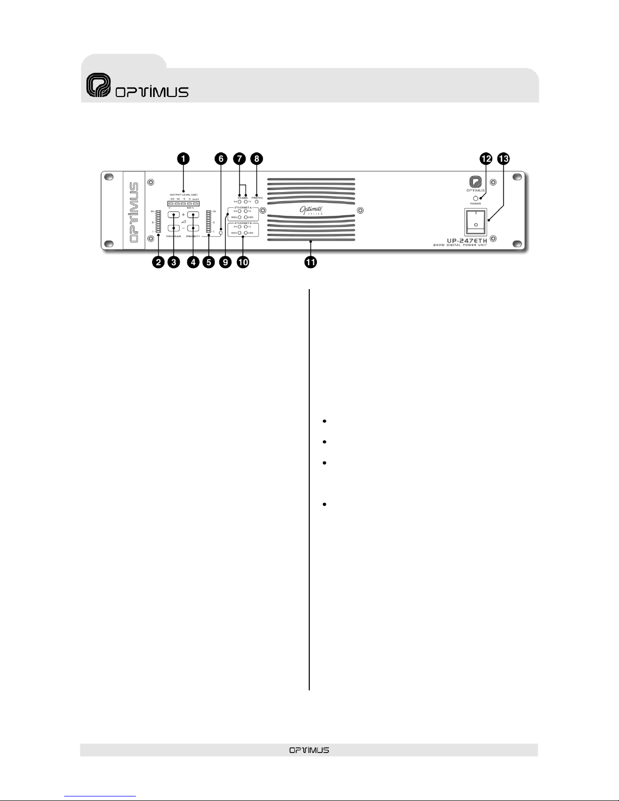
Local analog input channels: Emergency,
Priority and Program.
Low impedance (4-8-16 ohms) and high
impedance (50-70-100 V) loudspeaker line
output.
Protection against short circuit / overload in
the loudspeaker line.
They occupy two units of height in 19” Rack
cabinets.
Paging security auxiliary relay.
Battery power supply input (24 V DC).

UP-67ETH, UP-127ETH,
UP-247ETH, UP-367ETH
Digital power unit
UP-x7ETH version 1.1
7
2. BLOCK DIAGRAM

UP-67ETH, UP-127ETH,
UP-247ETH, UP-367ETH
Digital power unit
UP-x7ETH version 1.1
8
____________________________________
1The front volume controls do not affect the digital audio signal that
reaches the amplifier via IP. The volume of the digital signal is
controlled by means of the P.A. Manager software or from the
DC-600ETH / FC-600ETH desk.
The EMERGENCY analog input is not affected by the front volume
controls.
3. FRONT INDICATORS AND CONTROLS
(1) OUTPUT LEVEL indicator
Indicates the power supplied to the loudspeaker
line. The LED marked 0 dB indicates the point at
which the amplifier provides maximum power.
(2) PROGRAM volume level indicator
Indicates the volume level of the PROGRAM
input.
(3) PROGRAM + - volume controls
They control the audio volume of the PROGRAM1
local analog signal input.
(4) PRIORITY + - volume controls
They control the audio volume of the PRIORITY
analog signal input.
(5) PRIORITY volume level indicator
Indicates the volume level of the PRIORITY input.
(6) PRIORITY indicator
It lights:
a) When an announcement that comes from the
PRIORITY analog input is played.
b) When an announcement that comes from the
EMERGENCY analog input is played.
c) When an announcement configured as
PRIORITY that comes from one of the ETH
inputs is played.
d) When a pre-recorded message from the
internal Flash memory of the amplifier is
played.
e) When a pre-recorded message from the MP3
memory is played.
(7) RS485 RX –TX indicators
These indicate reception (RX) or transmission
(TX) of data through the RS485 port of the UP-
ETH.
(8) PROTEC. (PROTECTION) indicator
Lights when the internal protection of the
amplifier is in operation. It can be activated due
to an overload or short circuit in the loudspeaker
line or due to an excessive temperature inside
the amplifier.
(9) ETH A (ETHERNET A) indicators
RX: When lit, it indicates that data is being
received through the ETHERNET A input.
TX: When lit, it indicates that data is being
transmitted through the ETHERNET A input.
10 Mbps: Indicates the transmission speed
of the IP network (lit: 10 Mbps; unlit: 100
Mbps. The use of a transmission speed of 100
Mbps is highly recommended).
LINK: Indicates connection to the network
through the ETHERNET A input.
(10) ETH B (ETHERNET B) indicators
These serve the same purpose as the ETHERNET
A indicators, applied in this case to ETHERNET B.
(11) Ventilation input
This input must not, under any circumstances, be
obstructed.
(12) ON / OFF indicator
Lights up when the amplifier is operating,
whether by Mains supply or Battery.
(13) ON / OFF switch
Switch for turning on the amplifier. If the
amplifier is operating by battery, this switch has
no effect.
Figure 1

UP-67ETH, UP-127ETH,
UP-247ETH, UP-367ETH
Digital power unit
UP-x7ETH version 1.1
9
4. REAR ELEMENTS AND CONNECTIONS
(1) Connection to the 230 V AC mains supply
(2) Mains fuse
(3) Ventilation output (only UP-127ETH,
UP-247ETH and UP-367ETH)
(4) INPUT/OUTPUT CONTACTS
(5) Battery power supply input
(6) Ground to chassis connection
(7) FAIL SAFE relay
(8) Loudspeaker line outputs
(9) Paging security auxiliary relay
(10) USB input for download of pre-recorded
messages in MP3 format
(11) Emergency (EMG) volume
(12) PRE OUT volume
(13) Emergency input (EMERGENCY IN)
(14) Priority input (PRIORITY IN)
(15) Program input (PROGRAM IN)
(16) MAIN IN input
(17) PRE OUT output
(18) MAIN IN LINK switch
(19) RS-485 ADDRESS DIP switch
(20) RS485 RX and TX indicators
(21) RS485 IN connector
(22) RS485 OUT connector
(23) RS-485 OUT ON/OFF switch
(24) ETHERNET A input 10 Mb, ACT and LINK
LED indicators
(25) ETHERNET B input 10 Mb, ACT and LINK
LED indicators
(26) ETHERNET A connector
(27) ETHERNET B connector
(28) IP ADDRESS DIP switches
Figure 2

UP-67ETH, UP-127ETH,
UP-247ETH, UP-367ETH
Digital power unit
UP-x7ETH version 1.1
10
Do NOT under any circumstances obstruct this output
4.1. Connection to the 230 V AC
mains supply
Male socket CEE22 for connection to the 230 V
AC mains supply by means of the cable supplied
together with the amplifier.
On request, the units can be supplied for
operation with other mains voltages.
4.2. Mains fuse
This is located in the little box below the power
supply socket. There is also a spare fuse in the
same box. The value of the fuse varies depending
on the amplifier model.
Model
UP-67ETH
UP-127ETH
UP-127ETH
UP-367TH
Mains fuse
1.6 A
2.5 A
6.3 A
8 A
4.3. Ventilation output
(UP-127ETH, UP-247ETH and UP-367ETH
models)
4.4. Input/output contacts
The amplifier has nine configurable input / output
contacts.
To use these, the functionality of each contact
must be defined through the P.A. Manager
software (see section 6.2.3).
Contacts configured as input:
To activate a contact configured as input, this
contact must be connected to ground.
By way of example, these inputs are used to
detect and notify the system of alarms, or to
activate local pre-recorded messages…
Contacts configured as output
They are open collector outputs. These outputs
can be used to activate the selection of zones of
an MC-12/24L, activate the priority of an external
device, light a LED…
4.5. Battery power supply input
This supply allows the equipment to be used in
safety installations, connecting a 24 V DC
battery.
The ON/OFF switch does not cut off the supply
from the battery.
It is possible to monitor the presence of the 24 V
DC battery input.
The battery power fuse is situated inside the unit,
in the contact input/output circuit. To gain access
to the fuse, in the event of repair, it is necessary
to remove the cover of the unit. A spare battery
fuse is supplied with each amplifier. The value of
this fuse varies according to the amplifier model.
Model
UP-67ETH
UP-127ETH
UP-247ETH
UP-367TH
Battery
fuse
8 A
15 A
30 A
40 A
4.6. Ground to chassis
connection
In all Public Address installations it is very
important that there is one single point of
connection between the signal ground connection
and the mains supply ground contact.
If the Public Address installation is composed of
several equipment units, their chassis will
probably be joined, either by means of the
ground terminal of the mains connection, or
because they are mounted in a rack cabinet.
If the ground connections are also joined by the
signal circuits, it is advisable to remove the
jumper between the ground connection and the
chassis from all the units except one.

UP-67ETH, UP-127ETH,
UP-247ETH, UP-367ETH
Digital power unit
UP-x7ETH version 1.1
11
4.7. FAIL relay
Solid state relay. It switches when:
a) The power supply of the amplifier fails.
b) The maximum temperature set by the P.A.
Manager software is exceeded.
c) The connection in both Ethernet inputs (ETH A
and B) is lost.
d) A high impedance / open line fault is detected
in the loudspeaker line.
e) An internal communication or firmware error
is detected in the amplifier.
4.8. Loudspeaker line outputs
The loudspeaker line output is effected by means
of a transformer that has low impedance (4-8-16
ohms) and high impedance (50-70-100 V)
outputs.
The connection must be made between terminal
"0" and the terminal corresponding to the
selected impedance or voltage.
When working with the 50, 70 and 100 V lines, it
should be remembered that:
The loudspeakers must be equipped with a
line transformer.
The total connected power will be the sum of
the power absorbed by the loudspeakers and
this must be between 50% below and 20%
above the rated power of the amplifier.
The power absorbed by a loudspeaker with a
transformer is indicated on a 100 V line. If
the amplifier is connected to the 70 V line, it
will absorb half the indicated power, and if it
is connected to the 50 V line, it will absorb a
quarter of this power.
Figure 3
Total power absorbed: 60 W
Power absorbed by each
transformer: 12 W
Total power absorbed: 60 W
Power absorbed by each
transformer: 6 W
Total power absorbed: 60 W
Power absorbed by each
transformer: 3 W

UP-67ETH, UP-127ETH,
UP-247ETH, UP-367ETH
Digital power unit
UP-x7ETH version 1.1
12
4.9. Paging security auxiliary
relay
It switches:
a) When an announcement that comes from the
PRIORITY analog input is played.
b) When an announcement that comes from the
EMERGENCY analog input is played.
c) When an announcement configured as
PRIORITY and originating from one of the ETH
inputs is played.
d) When a pre-recorded message from the
Coldfire Flash memory of the amplifier is played.
e) When a pre-recorded message from the Flash
memory of the MP3 circuit of the amplifier is
played.
4.10. USB input for pre-
recorded messages in MP3 format
This connector allows to access to the amplifier
MP3 Flash memory.
This memory can store files in MP3 format to be
used as pre-recorded messages (see section
5.1).
4.11. Emergency (EMG) volume
Regulates the level of the signal applied to the
emergency input.
4.12. PRE OUT volume
Regulates the level of the PRE OUT output.
4.13. Emergency input (EMERGENCY IN)
Unbalanced local analog input through an RJ45 connector. Its sensitivity is 0 dBu (775mV).
It has absolute priority over any other signal from the amplifier (ETH inputs, PRIORITY and PROGRAM
inputs, and pre-recorded messages activated through the input/output contacts strip).
There are three types of emergency announcement:
Live voice emergency message: The audio channel of the emergency input is opened when pin
number 6 (speech preference) is connected to pin number 8 (GND) of the connector. Its activation has
priority over any other signal from the amplifier, including the other types of emergency
announcement.
Pre-recorded Evacuation message: This is pre-recorded message number 1 in the MP3 Flash
memory of the amplifier. It is activated when pin number 4 is connected to pin number 8 (GND) of the
connector. Its activation has priority over the activation of the pre-warning message and all other
signals from the amplifier.
Pre-recorded Pre-warning message: This is pre-recorded message number 2 in the MP3 Flash
memory of the amplifier. It is activated when pin number 5 is connected to pin number 8 (GND) of the
connector. Its activation has priority over all signals from the amplifier that are not emergency
signals.
Activation of any of the three types of emergency announcement activates the paging security auxiliary
relay (see section 4.9).
The emergency input has a single volume adjustment situated on the back of the unit (see Figure 2, no.
11) and this affects the volume of live voice messages.

UP-67ETH, UP-127ETH,
UP-247ETH, UP-367ETH
Digital power unit
UP-x7ETH version 1.1
13
Pin 1: Audio H (hot)
Pin 2: GND
Pin 3: Not used
Pin 4: Activation of message 1
from the MP3 memory of the
amplifier (evacuation
message).
Pin 5: Activation of message 2
from the MP3 memory of the
amplifier (pre-warning
message).
Pin 6: Priority contact of the
emergency input. Activates
the audio channel of the
emergency input for live voice
messages.
Pin 8: GND
Figure 4. Audio signal
connection, activation of
priority and activation of
emergency input messages 1
and 2.
Figure 5. Connection of the
emergency input with
contact surveillance.
Cat 5 STP cable must be used for the connections.
The Emergency input has Emergency Surveillance (critical path) and Activation Contacts
Surveillance:
Emergency Surveillance (critical path): The device connected to the emergency input must
generate a high frequency signal (17720 Hz, 18000 Hz, 19250 Hz or 20000 Hz). The system performs
a constant check of the high frequency signal, generating an alarm in the event of short circuit,
interruption of continuity or disconnection of this input. The alarm generated is sent through the IP
network towards the control PC or the equipment units prepared to receive these alarms
(DVA-102ETH, FC-600ETH, DC-600ETH). The emergency surveillance function must be configured by
means of the P.A. Manager software (see section 6.7).
Activation Contacts
Surveillance: If the connections
shown in Figure 5 are made, the
system monitors the priority
contact and the two contacts for
activation of pre-recorded
messages from the emergency
input. In the event of short circuit
or disconnection, an alarm is
generated.

UP-67ETH, UP-127ETH,
UP-247ETH, UP-367ETH
Digital power unit
UP-x7ETH version 1.1
14
Figure 6. Balanced and unbalanced signal
connection to the priority input
Pin 1: Audio H (hot).
Pin 2: GND
Pin 3: Acknowledge. Allows synchronisation with
external desks (MD-94 family).
Pin 4: Not used
Pin 5: Not used
Pin 6: Priority contact. Priority is activated when pin
number 6 is connected to pin number 8.
Pin 7: Supplies a voltage of 24 V DC that can be used
to power low consumption devices. The maximum
current supplied is 200 mA.
Pin 8: GND
To be able to view these alarms, it is necessary to enable their reception through the P.A. Manager
software. To do this:
1. From the installation screen, open the Options menu and select Alarms Management.
2. On the list of UP-ETH alarms, enable the Emerg. Contact Surveillance,Evac. Contact
Surveillance and Warning Contact Surveillance alarms.
3. Open the File menu and select Save.
4. Open the Optimax menu and select Send configurations to all Optimax equipments.
4.14. Priority input (PRIORITY IN)
Unbalanced analog input with an RJ45 connector and a sensitivity of 0 dBu (775 mV).
It has a priority contact which is activated by connecting pin no. 6 to pin no. 8 of the connector. When
this contact is activated, any signal of a lower priority level is cut off and priority is given to the PRIORITY
IN input, while the paging security auxiliary relay is activated at the same time.
This input is particularly suitable for receiving local announcements (e.g. a microphone with a speech
preference button…).
Cat 5 STP cable must be used for its connection.

UP-67ETH, UP-127ETH,
UP-247ETH, UP-367ETH
Digital power unit
UP-x7ETH version 1.1
15
4.15. Program input (PROGRAM IN)
Unbalanced analog input with an
RJ45 connector and a sensitivity
of 0 dBu (775 mV).
It is especially suitable for
receiving a local program signal
(e.g. a CD player, tuner…).
Use Cat 5 STP cable for its
connection.
4.16. MAIN IN
Unbalanced analog input with an RJ45 connector and a
sensitivity of 0 dBu (775 mV).
It is used, together with the PRE OUT output, to insert a unit
(equaliser, anti-larsen...) between the preamp and the power
unit of the amplifier (see Figure 10).
To enable this input, move the LINK switch of the MAIN IN input
to ON.
Use Cat 5 STP cable for its connection and refer to Figure 8.
4.17. PRE OUT
Unbalanced analog output with an RJ45 connector and a
sensitivity of 0 dBu (775 mV).
The audio signal is always present in this output.
It is used, together with the MAIN IN input, to insert a unit
(equaliser, anti-larsen…) between the preamp and the power
unit of the amplifier (see Figure 10), or to send a signal to
other power units (see Figure 11).
It has an output priority contact, which is activated according
to the configuration of the power unit (see section 6.2.2).
Use Cat 5 STP cable for its connection and refer to Figure 9.
Pin 1: Audio H (hot).
Pin 2: GND
Pin 3: Not used
Pin 4: Not used
Pin 5: Not used
Pin 6: Not used
Pin 7: Not used
Pin 8: GND
Figure 7. Balanced and unbalanced signal connection to the program input
Figure 8
Figure 9

UP-67ETH, UP-127ETH,
UP-247ETH, UP-367ETH
Digital power unit
UP-x7ETH version 1.1
16
4.18. MAIN IN LINK
Sliding this switch to ON disconnects all the audio signals from the amplifier input, connecting only the
MAIN IN input.
Figure 10
Figure 11

UP-67ETH, UP-127ETH,
UP-247ETH, UP-367ETH
Digital power unit
UP-x7ETH version 1.1
17
4.19. RS-485 ADDRESS DIP
switch
This is used to assign a communication address
to the unit, within an RS485 bus. Each unit
connected to an RS-485 bus must have a
different address.
The type of protocol used is CSMA (Carrier Sense
Multiple Access).
For configuration, refer to Table I on the next
page.
4.20. RX and TX indicators
Reception (Rx) and transmission (Tx) indicators
of the RS485 bus.
4.21. RS485 IN connector
RJ45 type connector. This is used to connect the
amplifier to an RS485 communication bus.
For its connection, refer to Figure 12.
4.22. RS485 OUT connector
RJ45 type connector. Its purpose is to give
continuity to the RS485 bus and connect other
elements.
If this output is used, the RS-485 ON/OFF switch
must be moved to the ON position.
For its connection, refer to Figure 12.
4.23. RS485 ON/OFF
In the ON position, it enables the RS-485 OUT
connector, and in the OFF position, it loads the
bus with the end of line impedance.
If the amplifier is the first or last element of the
RS-485 bus, the switch must be moved to the
OFF position. If the amplifier is an intermediate
element of the RS-485 bus, the switch must be
moved to the ON position.
Figure 13 shows an example on an RS485 bus
formed by three amplifiers and several NS-485
noise sensors.
Figure 12
Figure 13

UP-67ETH, UP-127ETH,
UP-247ETH, UP-367ETH
Digital power unit
UP-x7ETH version 1.1
18
Table I. Configuration of DIP switches.

UP-67ETH, UP-127ETH,
UP-247ETH, UP-367ETH
Digital power unit
UP-x7ETH version 1.1
19
N.B.: The IP address can also be set by software. To do
this, refer to section 7. If this action is taken, the IP
ADDRESS DIP switches of the amplifier cease to be
operative.
4.24. ETHERNET A input 10 Mb,
ACT and LINK LED indicators
10 Mb: Indicates the speed of the IP network
connected to the ETHERNET A input. If the LED is
lit, it indicates a speed of 10 Mb. If unlit, it
indicates a network speed of 100 Mb (use of a
transmission speed of 100 Mbps is highly
recommended).
ACT: ACTIVITY indicator. It lights when data is
being sent or received through the ETHERNET A
input.
LINK: When lit, it indicates the connection of the
ETHERNET A input with the HUB or SWITCH.
4.25. ETHERNET B input 10 Mb,
ACT and LINK LED indicators
These serve the same purpose as the ETHERNET
A indicators, applied in this case to the
ETHERNET B input.
4.26. ETHERNET A connector
RJ45 type connector. Used for connection to the
IP network. Cat 5 STP cable must be used for its
connection.
4.27. ETHERNET B connector
RJ45 type connector. Used, in a redundant
network, as a secondary connection to the IP
network. Cat 5 STP cable must be used for its
connection.
If the connection to ETH A fails, the amplifier
automatically switches to this B connection, so
that the PA system continues to operate.
4.28. IP ADDRESS DIP switches
The IP address of the amplifier is configured
through these 4 DIP switches. This address
identifies the amplifier in the network, and so
each unit must have a unique IP address.
An IP address is represented by means of a 32-
bit binary number. The IP addresses are
expressed as decimal notation numbers: the 32
bits of the address are divided into four octets
(an octet is a group of 8 bits). In the amplifier,
each octet is represented by A0 to A7 for the first
octet, B0 to B7 for the second octet, C0 to C7 for
the third octet, and D0 to D7 for the fourth octet.
In an octet, each bit can have the value 0 (DIP
switch OFF) or 1 (DIP switch ON). In order to
obtain the decimal value of the octet, the decimal
values of each bit that is in the ON position must
be added up (from left to right: 1, 2, 4, 8, 16,
32, 64 and 128).
Figure 14 shows an example in which the IP
address 192.168.100.128 is configured.
Table I shows all the DIP switch combinations
from 0 to 255.
Figure 14

UP-67ETH, UP-127ETH,
UP-247ETH, UP-367ETH
Digital power unit
UP-x7ETH version 1.1
20
5. LOCAL PRE-RECORDED MESSAGES
The amplifier has two internal memories in which files can be stored for subsequent use as local pre-
recorded messages: MP3 Circuit Memory and Coldfire Flash Memory.
5.1. Pre-recorded messages resident in the MP3 circuit memory
5.1.1. Characteristics
Access/Updating of messages
Through the USB connector on the rear panel, by means of a PC
Memory capacity
16 Mb
Maximum number of messages
20
File format
MP3
The messages contained in the MP3 memory are immediately available when the amplifier is switched on,
thereby complying with the standard EN60849.
5.1.2. Transfer of messages to the MP3 memory of the amplifier
The files must be copied to the MP3 memory with a specific name format. Otherwise the messages
cannot be played.
The MP3 files must have the CRC protection activated (the majority of recording programs support this
option). This ensures constant surveillance of the integrity of messages 1 and 2 in the MP3 memory (files
0001… and 0002…). If there were to be any problem in these files, the amplifier sends an alarm message
through the IP connection towards the different units in the installation that have the capacity to receive
it (FC-600ETH, DC-600ETH, DVA-102ETH, UMX-02/0, control computer…).
To transfer the MP3 files to the amplifier, connect the computer that contains the messages to the
amplifier by means of the USB connector on the rear panel of the amplifier. Use the PC browser to copy
the files to the MP3 memory of the amplifier, which will be shown as an additional disk unit. The files
must be copied into the root directory of the unit, and folders should not be used.
This manual suits for next models
3
Table of contents
Popular Portable Generator manuals by other brands

Generac Power Systems
Generac Power Systems XG7000E XG SERIES specification

Promate
Promate PM7500 ES Operator's manual

Champion Global Power Equipment
Champion Global Power Equipment 100520 Operator's manual

ACDelco
ACDelco AC-G0005 instruction manual

Powermate
Powermate PM0543000.01 user manual

Powermate
Powermate PMA535202 product manual