UMX-LNK version 5.0.001 ENG
Audio link card for modular master matrix
(COMPACT or UMX-03/0)
DIP Switch 1: ON
DIP Switch 2: OFF
DIP Switch 3: ON
DIP Switch 4: OFF
DIP Switch 5: Connects the metal housing of the RJ45 INPUT 1
and OUTPUT 1 connector to the chassis (factory default: ON)
DIP Switch 6: Connects the metal housing of the RJ45 INPUT 1
and OUTPUT 1 connector to the GND (factory default: ON)
DIP Switch 7: Connects the metal housing of the RJ45 INPUT 2
and OUTPUT 2 connector to the GND (factory default: ON)
DIP Switch 8: Connects the metal housing of the RJ45 INPUT 2
and OUTPUT 2 connector to the chassis (factory default: ON)
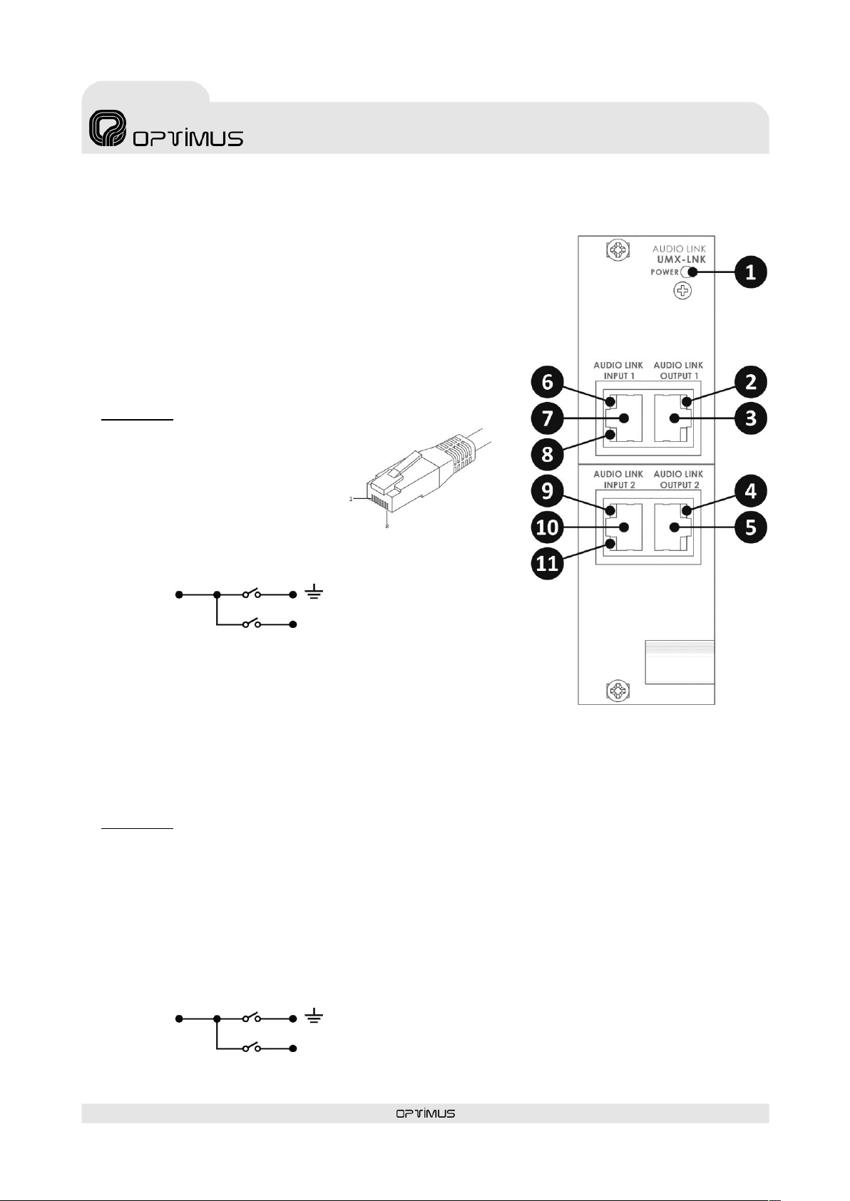
6) Green LED. Shows the status of the AUDIO LINK INPUT 1
connection. LED ON indicates correct connection.
7) RJ45 connector AUDIO LINK INPUT 1.
The card constantly monitors this connection, turning ON the
yellow LED 8) and showing an alarm through the PA
management software in case of fail or disconnection.
Pin 1: CHANNEL 1 AUDIO INPUT HOT.
Pin 2: CHANNEL 1 AUDIO INPUT COLD.
Pin 3: CHANNEL 2 AUDIO INPUT HOT.
Pin 4: CHANNEL 3 AUDIO INPUT COLD.
Pin 5: CHANNEL 3 AUDIO INPUT HOT.
Pin 6: CHANNEL 2 AUDIO INPUT COLD.
Pin 7: INPUT SURVEILLANCE LINK 1.
Pin 8: GND.
Metal Shield
8) Yellow LED. If it turns ON it indicates that the AUDIO LINK
INPUT 1 connection failed or was disconnected.
9) Green LED. Shows the status of the AUDIO LINK INPUT 2
connection. LED ON indicates correct connection.
10) RJ45 connector AUDIO LINK INPUT 2.
The card constantly monitors this connection, turning ON the
yellow LED 11) and showing an alarm through the PA
management software in case of fail or disconnection.
Pin 1: EMERGENCY CHANNEL AUDIO INPUT HOT.
Pin 2: EMERGENCY CHANNEL AUDIO INPUT COLD.
Pin 3: 24 VDC LINK (Degraded mode functionalities:
Through pin 3, the card is powered from the other
matrices, which guarantees its operation even in
the event that the matrix itself is not powered).
Pin 4: CHANNEL 4 AUDIO INPUT COLD.
Pin 5: CHANNEL 4 AUDIO INPUT HOT.
Pin 6: EMERGENCY PRIORITY INPUT CONTACT.
Pin 7: INPUT SURVEILLANCE LINK 2.
Pin 8: GND.
Metal Shield
11) Yellow LED ON: If it turns ON it indicates that the AUDIO
LINK INPUT 2 connection failed or was disconnected.
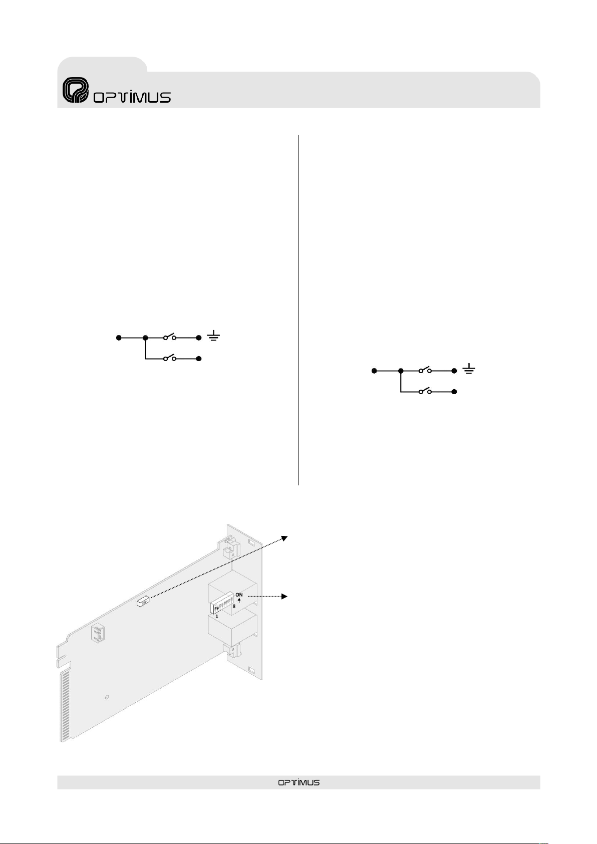
3. CONFIGURATION
* In the AUDIO LINK INPUT 1 connector, the connection to the
chassis of the equipment is made through the Internal DIP Switch
5 and the connection between the shielding of the connector to
the GND is made through the internal DIP Switch 6.
* In the AUDIO LINK INPUT 2 connector, the connection to the
chassis of the equipment is made through the Internal DIP Switch
8 and the connection between the shielding of the connector to
the GND is made through the internal DIP Switch 7.
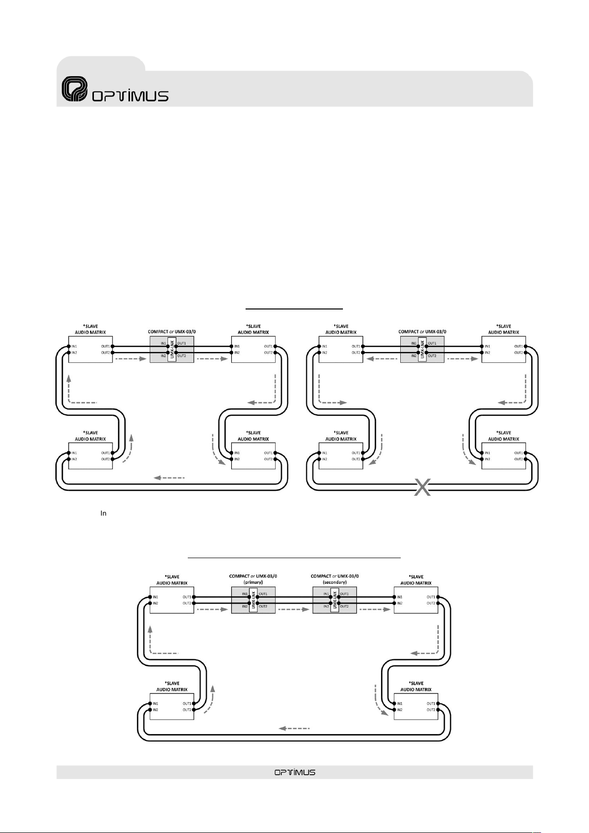
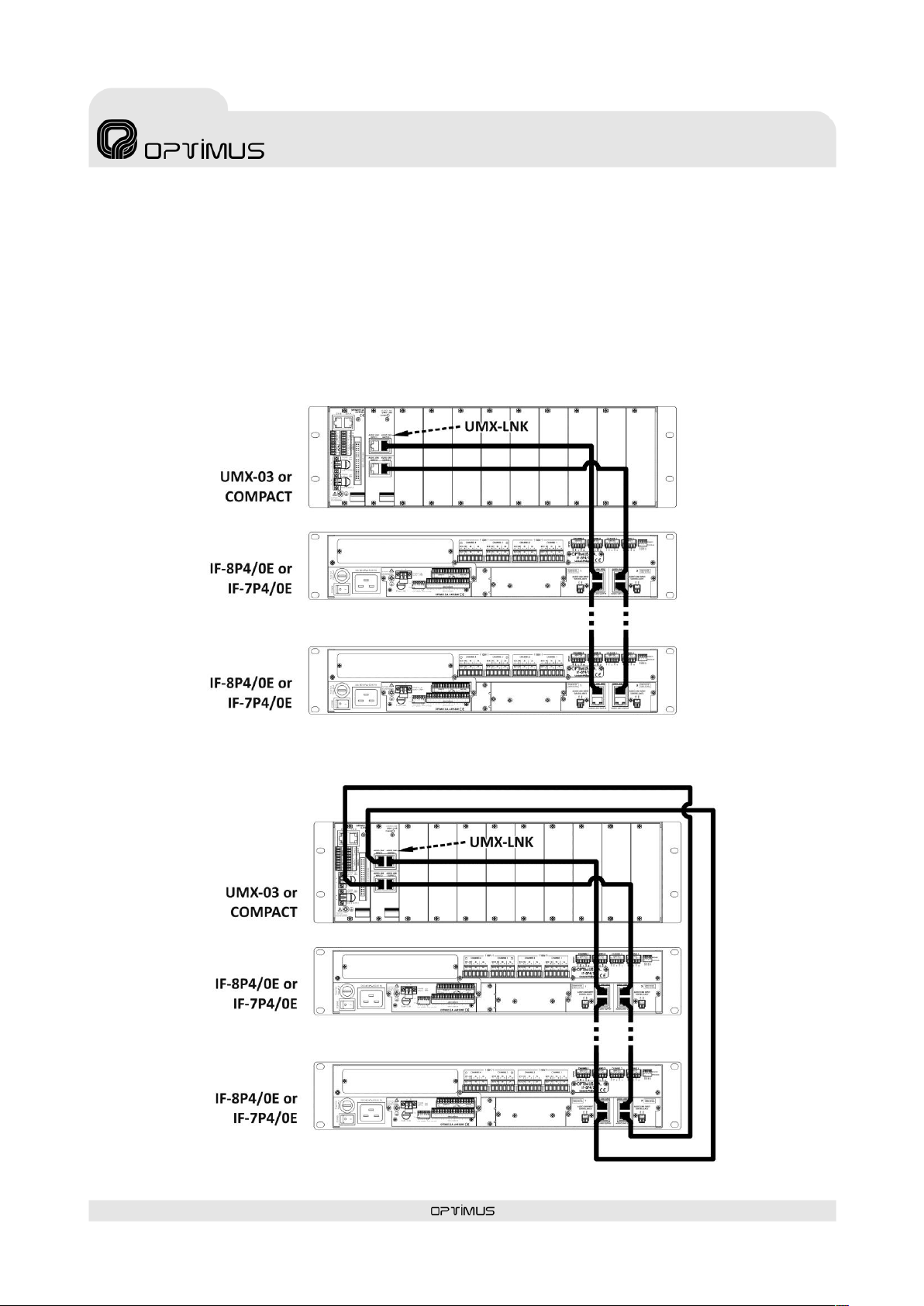
MODE SELECTOR (In fully redundant installations)
ON: PRIMARY MODE (factory default)
OFF: SECONDARY MODE (for secondary UMX-03/0 IN
FULLY REDUNDACE INSTALLATIONS)