manuals.online logo
Brands
  1. Home
  2. •
  3. Brands
  4. •
  5. OptiSource
  6. •
  7. Lens
  8. •
  9. OptiSource LENS INSPECTION STATION+ User manual

OptiSource LENS INSPECTION STATION+ User manual

1
CONTENTS
1. Configuration………………………………………………………………………………….02
2. Installation………………………………………………………………………………….….03
3. Operation Procedures…………………………………………………………………….….04
4. Operation Indicator Light………………………………………………………………….….06
5. Accessories………………………………………………………………………………...….07
6. Cleaning and maintenance………………………………………………………..……...….07
7. Trouble Shooting Guide…………………………………………………………………...….07
8. Specifications……………………………………………………………………………….....07
LENS INSPECTION STATION +
USER MANUAL
1-800-OptiSource (678-4768) | 1-800-OptiSource.com | Text Us: (631) 371-0524 - 2 -
5
Steps:
A. Put PAL/Inspection Top lens on the upper window. The direction mark is aligned with U-shaped groove.
B. Put PAL BOTTOM lens on the lower window. The direction mark is aligned with U-shaped groove.
C. Power on. Put the progressive lens above the parallel light grid and observe the four areas of the lens.
D. After confirming the four areas, keep the distant area and near area in a horizontal line and find out the
invisible marks on both sides.
E. ADD value is usually on one side and the brand marks would be on the other side.
4) Function II –Polariscope
Steps:
A. Put Polariscope TOP lens on the upper window. The direction mark is aligned with U-shaped groove.
B. Put Polariscope BOTTOM lens on the lower window. The direction mark is aligned with U-shaped groove.
C. Put the assembled lens between two polarized lenses.
D. If it shows the same as below picture, the lens stress is not in a balance. The imbalance is proportional to the
darkness of the color. The lens stress can be reduced by edging the darkest part of the lens.
- 3 -
4
4) Rotate the angle adjustment knob, the inclination of the base can be adjusted.
3. Operation Procedures
1) Connect Power
Insert the power adapter and turn on the machine.
Rechargeable batteries and DC power supply are both available. With the rechargeable batteries inside, after
connecting power, DC power supply mode will be enabled first.
2) Select the inspection lenses
On each lens, there are fingerprint mark and direction mark, as below picture. It’s much easier to take out the
lenses with the fingerprint mark. When you put the lens back, the direction mark must be aligned with the slot,
then insert the lens.
3) Function I - PAL Identifier
With black grid, LED backlight and high magnification lens, you could inspect the progressive lenses (multifocal
lenses) easily and efficiently.
Manufacturers’ marks
Lens type ID
Invisible Marks
ADD power
- 4 -
2
1. Configuration
1.1 Main body
1. Upper Inspection Window
2. Frame
3. Lower Inspection Window
4. Lens Storage Slot
5. Power Indicator Light
6. Power Switch
7. Battery Chamber
8. Operation Indicator Light 1
9. Operation Indicator Light 2
10. Operation Indicator Light 3
11. Power Socket
12. Lens Storage Slot
13. Angle Adjustment Knob
1.2 Lenses
PAL/Inspection TOP PAL BOTTOM Inspection BOTTOM
- 6 -
3
Polariscope TOP Polariscope BOTTOM
2. Installation
1) Loosen two screws at the bottom, remove the cover.
2) Loosen two screws on the L-shape frame. Insert the frame into the base.
3) Fasten two screws at the bottom to fix the frame. Install the back cover and fasten the screws. Then, the
installation of the lens inspection station is completed.
- 5 -
7
5. Accessories
A. 5X lenses
B. Power adapter
6. Cleaning and maintenance
Keep the lens inspection station dry and clean. Please clean it with lens cleaner or soft cloth.
Caution: please do not clean with alcohol or any corrosive cleanser to avoid damage of the surface.
7. Trouble Shooting Guide
1) Connect the power and turn on the machine. If the light is not on, it may be caused by the bad connection of
the power socket. Rotate the power adapter connection port slightly to check if the machine could light up.
2)When the machine uses the battery power, if the light of the lower inspection window flashes, it means the
voltage is lower than 2.8V, please charge the batteries or use AC power.
If it still can’t work, please contact the Repair department or an authorized distributor.
8. Specifications:
1) Power: AC 100-240V 50-60Hz 0.4A
2) Power Adapter: DC 5V-6.5V 3A (6.5V MAX)
3) Dimension: 230*150*320mm
4) Weight: 1.65kg
5) Optional accessory:18650 rechargeable battery(12580mWh) * 2
Subject to change in design or specifications without advance notice
Version 1.0
- 8 -
6
If Lens stress has not been dealt with properly, the patient looks forward without any problem, but when he looks
aside, he would feel uncomfortable and unclear view exists. This situation usually appears on the full or half frame
eyeglasses, but not for the rimless ones.
The stress of PC lens can’t be avoided. However, the imaging quality will be much better if the lens stress is
small.
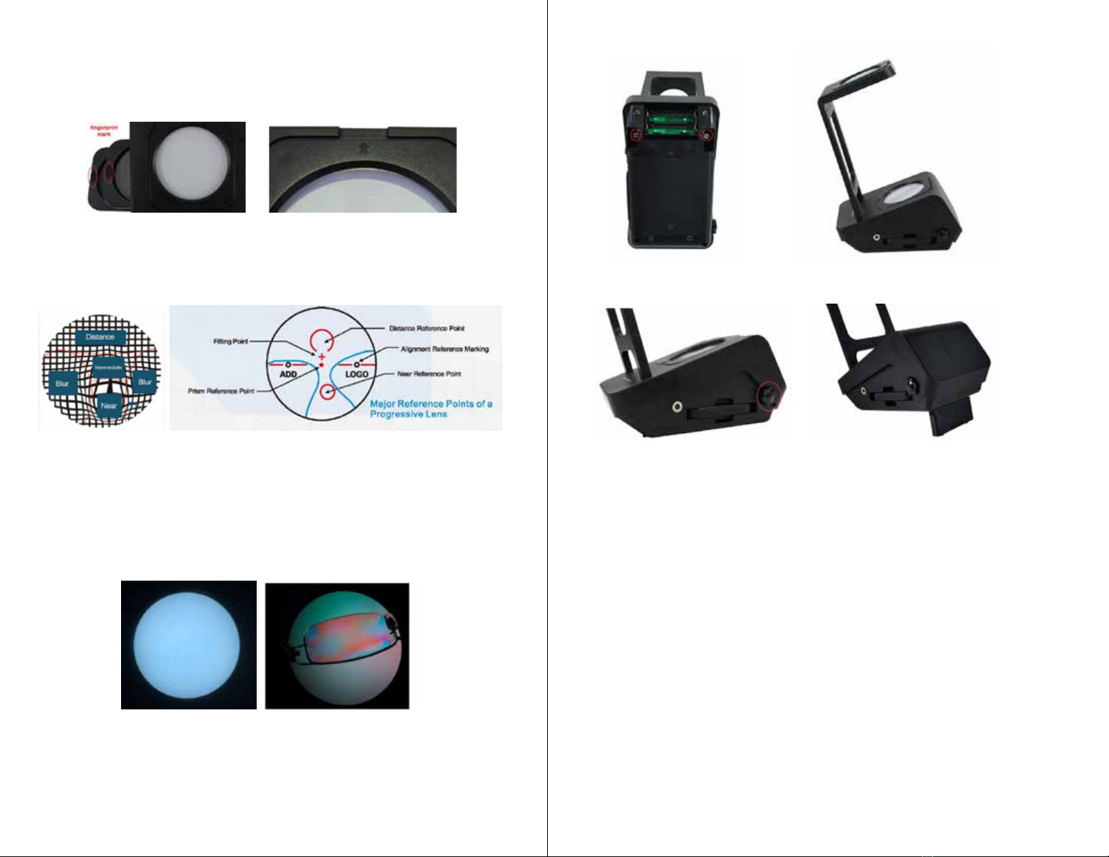
5) Function III - Final Inspection
Steps:
A. Put PAL/Inspection TOP lens on the upper window. The direction mark is aligned with U-shaped groove.
B. Put Inspection BOTTOM lens on the lower window. The direction mark is aligned with U-shaped groove.
C. Put the lens between the inspection lenses. Observe the surface of the lens.
D. Scratching, bubbling and other coating problems can be checked out.
4. Operation Indicator Light
Operation Indicator Light Instructions The order of the
indicator lights
Indictor
Status
Operation
Indicator 1
Operation
Indicator 2
Operation
Indicator 3 Note At the battery chamber
side, from left to right:
5V DC power, without
battery
flash on on
Without battery,
indicator 1 flashes
Operation Indicator 1
:
Charging(red)
5V DC Power, with
battery
on off on
The batteries are not
fully charged
Operation Indicator 2:
Full(green)
off on on
The batteries are fully
charged
Battery Power off off on
5V DC power is not
connected
Operation Indicator 3
:
Booster(green)
- 7 -

Popular Lens manuals by other brands

Canon HJ40E Operation manual

Canon

Canon HJ40E Operation manual

Samsung 20-50 mm F3.5-5.6 ED II user manual

Samsung

Samsung 20-50 mm F3.5-5.6 ED II user manual

TeleVue 17mm ETHOS instructions

TeleVue

TeleVue 17mm ETHOS instructions

Canon CN7x17 KAS S/E1 user manual

Canon

Canon CN7x17 KAS S/E1 user manual

Sony E PZ 16-50mm F3.5-5.6 OSS quick start guide

Sony

Sony E PZ 16-50mm F3.5-5.6 OSS quick start guide

Schneider Kreuznach PC-TS SUPER-ANGULON 2.8/50 HM user manual

Schneider Kreuznach

Schneider Kreuznach PC-TS SUPER-ANGULON 2.8/50 HM user manual

Leica APO-SUMMICRON-SL 1:2/75 ASPH. instructions

Leica

Leica APO-SUMMICRON-SL 1:2/75 ASPH. instructions

LAOWA C-Dreamer instruction manual

LAOWA

LAOWA C-Dreamer instruction manual

Samsung NX-M 9 mm F3.5 ED user manual

Samsung

Samsung NX-M 9 mm F3.5 ED user manual

Navitar 1-62315 Dimensional drawing

Navitar

Navitar 1-62315 Dimensional drawing

ARRI Tilt Focus instruction manual

ARRI

ARRI Tilt Focus instruction manual

Canon EF-M instructions

Canon

Canon EF-M instructions

Navitar 1-51324 Dimensional drawing

Navitar

Navitar 1-51324 Dimensional drawing

Meade LNT SmartFinder installation instructions

Meade

Meade LNT SmartFinder installation instructions

Panamorph CDR-S4 installation guide

Panamorph

Panamorph CDR-S4 installation guide

Canon EF100-400mm f/4.5-5.6L IS II USM instructions

Canon

Canon EF100-400mm f/4.5-5.6L IS II USM instructions

Navitar 1-51202 Dimensional drawing

Navitar

Navitar 1-51202 Dimensional drawing

Fantasea Line SEL30M35 instruction manual

Fantasea Line

Fantasea Line SEL30M35 instruction manual

manuals.online logo
manuals.online logoBrands
  • About & Mission
  • Contact us
  • Privacy Policy
  • Terms and Conditions

Copyright 2025 Manuals.Online. All Rights Reserved.